
A hollow shaft is exactly what the name says: a power-transmitting shaft with a bore through its center — a large-diameter, thin-walled tube machined at both ends, sometimes with flanges, splines or gear features. Designers choose hollow sections because they deliver far more bending and torsional stiffness per kilogram than solid sections; the same geometry that makes them efficient also makes them the most delicate workpieces in the straightening shop. A wall only a few millimeters thick on a shaft two hundred millimeters in diameter will not forgive tooling, load paths or measurement setups designed for solid bar.
This page is about hollow transmission shafts as machined components — tubes that have been cut, welded, machined, heat-treated and ground into a functional part. It is deliberately distinct from the thin-walled metal pipe solution, which covers raw tubing production; a finished hollow shaft with machined ends, a weld seam and tight runout specs is a different engineering problem from straightening pipe stock. A hollow shaft straightening solution must answer five questions:
- What are the wall thickness, diameter and L/D — and where does local stability end?
- Is the deviation pure centerline bend, ovality, or the coupled combination that hollow sections produce?
- Which measurement setup separates ovality from bend instead of mixing them?
- Which correction route is approved — external point pressing with protected tooling, combined press-and-round, or internal pressure methods?
- How is acceptance proven — runout map, ovality at stations, wall deformation evidence, and weld-zone integrity?
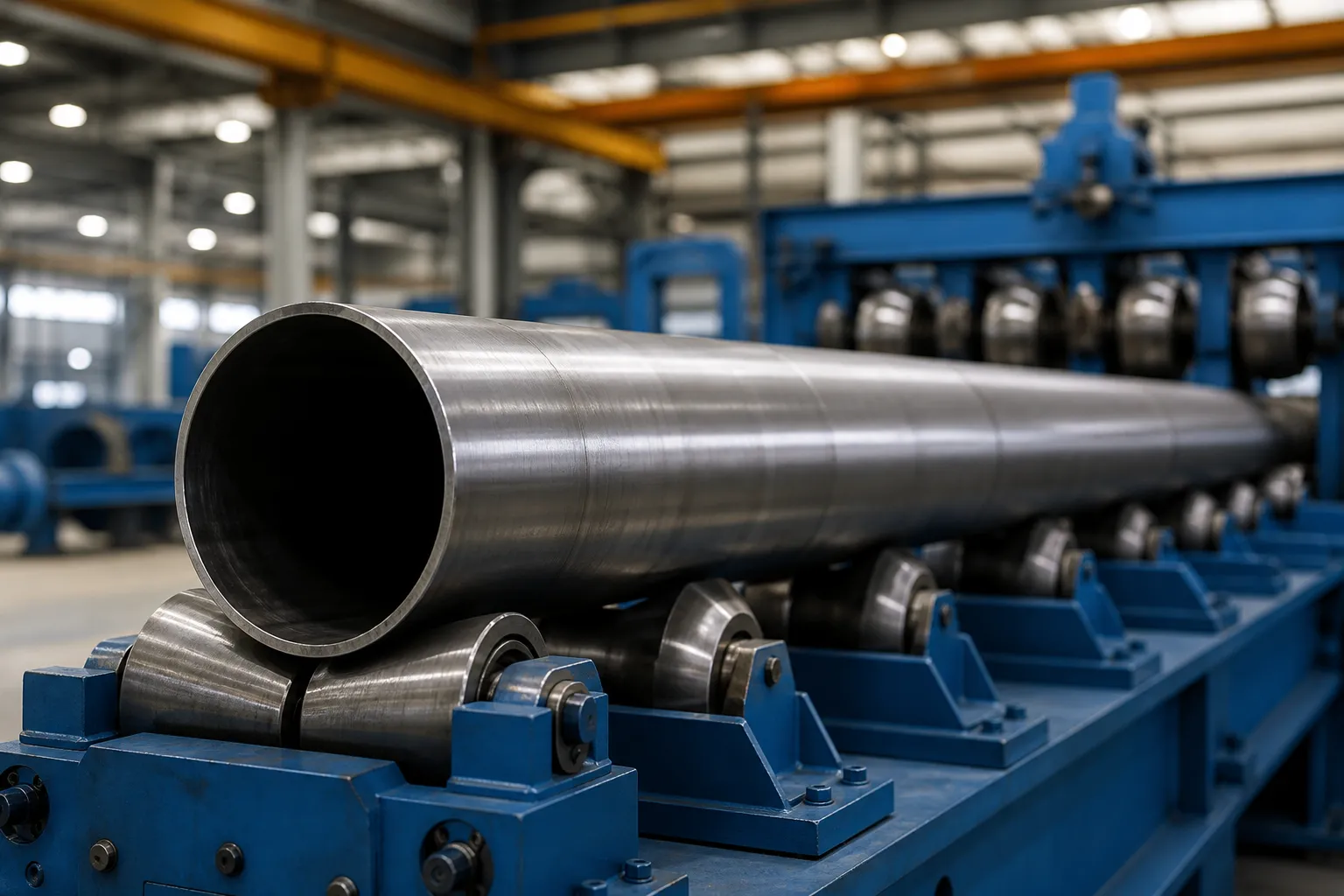
*Engineering concept illustration: a large hollow shaft supported in a straightening machine for a controlled correction study. It is not a customer-site photograph. Support spacing, force limits and route selection require drawings and representative sample tests.*
Why Hollow Shafts Break the Default Straightening Rules
Every rule that works on a solid shaft needs re-examination when the center is empty:
- The section can dent. A point load that a solid shaft shrugs off produces a permanent local flat on a thin wall. The anvil, the ram, and every support must spread load — the tooling discipline in surface protection tooling for straightening is not optional here.
- Bend and ovality are coupled. Bending a tube ovalizes the section at the bend; ovalizing a tube (for example in a chuck or on a hard V) shifts the measured axis. The two errors trade into each other under correction.
- Springback is different. A thin-walled section stores and releases strain differently from a solid one, and local yielding at the wall can precede full-section plastic bending — the compensation rules in shaft straightening springback compensation must be revalidated, not imported.
- The weld seam is a discontinuity. A longitudinal or girth weld has its own residual stress, hardness and sometimes distortion signature; loading across it follows different rules than loading the parent tube.
Where Hollow Shafts Deform
- Welding. A longitudinal seam weld shrinks and bows the tube toward the weld; girth welds at flanges tilt or bow the axis near the joint. This is the dominant source on welded hollow shafts and often the reason a straightening station exists in the line.
- Heat treatment. Stress relief, hardening or nitriding releases machining and welding stresses unevenly around the section; the post-treatment rules in straightening after heat treatment govern whether and when correction is allowed.
- Machining. Boring the ID or turning the OD removes stress asymmetrically (worst on seam-welded tube where the weld side differs from the opposite side), and the shaft bows after it comes off the machine.
- Clamping and handling. A chuck gripping a thin wall ovalizes it; a sling point on an unsupported span can leave a permanent set. Much “mystery bend” in hollow shafts is a handling artifact that correct tooling eliminates.
Hollow Shaft Families and Their Correction Windows
“Hollow shaft” covers a spread of geometries, and the correction window — how much correction is possible before wall damage or instability — narrows sharply as the wall gets thinner relative to the diameter:
| Family | Typical D/t | Correction Character |
|---|---|---|
| Heavy-wall hollow shaft | D/t below ~10 | Behaves nearly like solid bar; conventional point pressing with standard protections |
| Medium-wall transmission shaft | D/t ≈ 10–25 | Spread-load tooling mandatory; ovality coupling must be managed explicitly |
| Thin-wall precision shaft | D/t above ~25 | Local dimpling dominates; bend-and-round sequencing, very small strokes, non-contact measurement |
| Raw thin-wall tubing | any | Different problem entirely — see the pipe solution page |
Freeze the Stage: Welded, Heat-Treated or Finish-Machined
As with every precision-relevant part, the correction recipe is stage-bound:
- After welding, before stress relief: correction is possible but usually premature — a subsequent stress relief will move the geometry again. Measure, relieve, then correct.
- After stress relief / heat treatment: the geometry is stable and the residual-stress state is known — the preferred correction point for welded hollow shafts.
- After final machining and grinding: correction is restricted to small, documented strokes with spread tooling; machined surfaces (flange faces, journals, splines) may not be loaded, which constrains support and ram placement to designated zones.
- In a repair context: an unknown history (overload, impact, prior straightening) demands inspection gates before correction — a bent hollow shaft that has seen buckling instability must be evaluated for wall damage before any press touches it.
Each stage transition also changes the measurement datum availability: before machining, the bore or weld-run geometry may be the only datum; after machining, the functional journals and flange faces take over, and the correction targets must be re-referenced to the new datum chain per the logic in stepped shaft measuring datum selection.
Measurement: Separate the Two Geometries
The central measurement skill on hollow shafts is refusing to let ovality masquerade as bend:
- Rotate and map at several stations. With the shaft on roller (not sharp V) supports at fixed stations, record runout at multiple axial planes. The ovality versus centerline straightness distinction is the working tool: twice-per-revolution components are ovality, the migrating once-per-revolution component is the bend.
- Watch support-induced ovality. A hard support locally ovalizes a thin wall and shifts the axis reading by itself. Roller supports, wide pads and support-span discipline keep the measurement honest — the loaded versus released measurement framework applies with extra force.
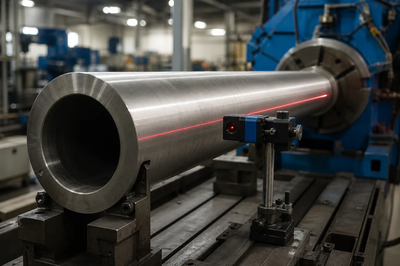
- Use non-contact sensing where tolerance is tight. Laser or air-gauge stations measure without deforming the wall; multi-station electronic mapping follows the architecture in LVDT multi-point shaft measurement.
- Fix the datum chain. Machined journal or pilot features define the functional axis; the datum-selection logic in stepped shaft measuring datum selection tells you which surfaces may serve as supports and which must only be measured.
Correction Routes for Hollow Sections
External Point Pressing with Spread Loads
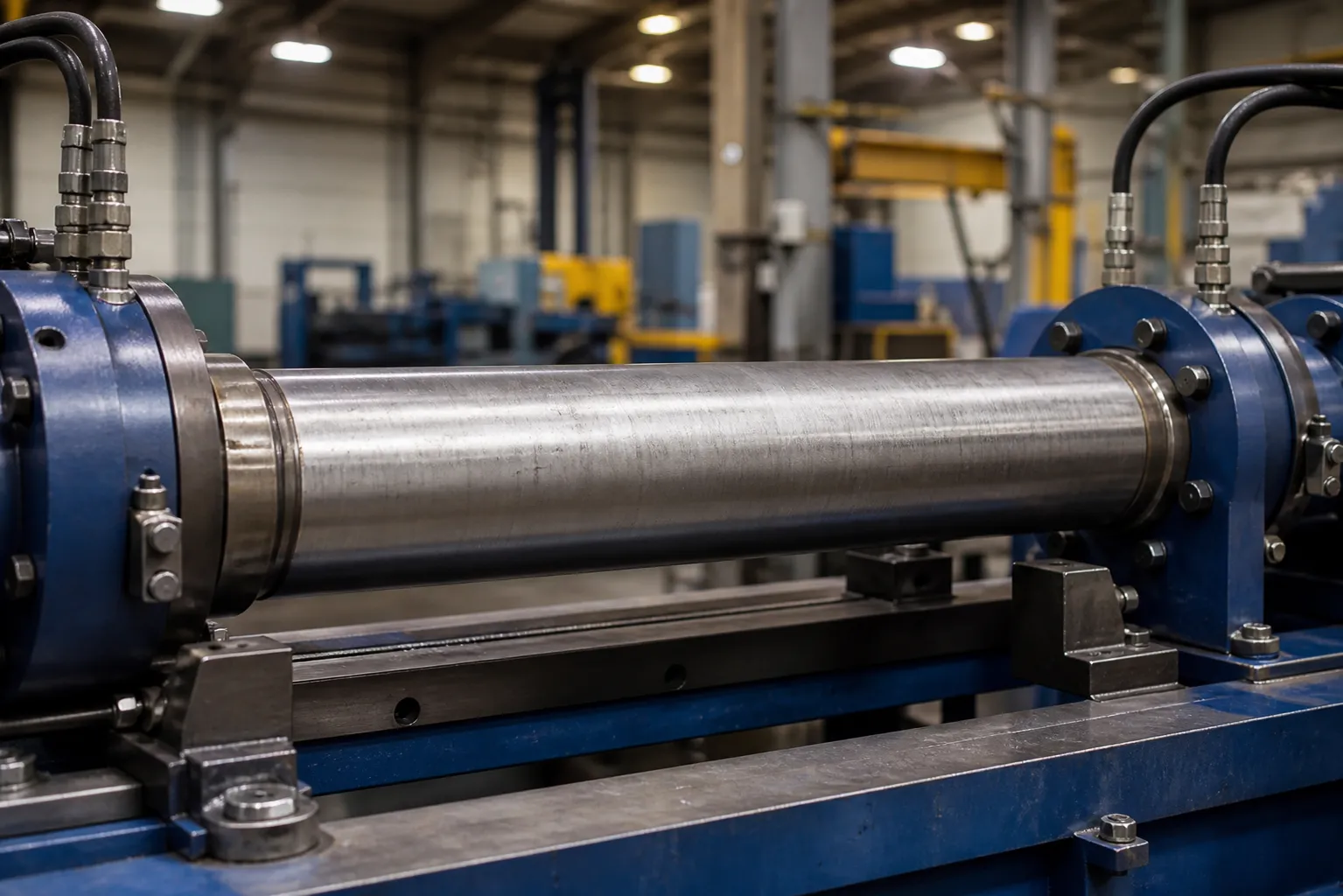
The baseline route is the precision point-press straightening process, adapted: wide-radius anvils and a radiused or padded ram spread the load over enough arc length that the wall bends as a section instead of dimpling locally. Supports sit per the bend map, clear of weld seams where possible. Stroke is displacement-controlled and small; on thin walls, visible wall deformation is a process failure, not a side effect. The trade-offs against roll-based routes are compared in press straightening versus roller straightening — with the caveat that rotary roll straightening is rarely acceptable on finished machined hollow shafts, because roll contact marks machined surfaces and thin walls ovalize under roll load.
Bend-and-Round Sequences
When ovality and bend coexist, the correction plan sequences them deliberately: round the section first (local forming to restore wall curvature), then correct the centerline, then re-map — because each step perturbs the other. Attempting both simultaneously with one setup is how a hollow shaft ends up with a helix of small dents along its length.
Internal Pressure Methods
For suitable geometries — open bores, sound welds, closed ends by tooling — internal hydraulic pressure can be used to size and stress-relieve the section, sometimes reducing bow as a side effect of uniform plastic expansion. This is a specialized route that depends entirely on the part’s pressure capability and weld qualification; it belongs in the conversation only where the drawing and weld documentation support it.
Acceptance Criteria
- Centerline straightness / TIR at the drawing-specified supports and stations, in the same measurement condition as the incoming map.
- Ovality at defined stations re-measured after correction; the correction must not purchase straightness with roundness.
- Wall integrity: no visible dents, flats or witness marks; wall-thickness spot checks where forming was applied.
- Weld-zone condition: no cracking indication where correction loads crossed or approached seams; inspection method per the weld class.
- Stability: a defined settling or stress-relief policy so the corrected geometry holds through subsequent machining and assembly — the Bauschinger effect and residual-stress redistribution are live issues on thin sections.
- Gauge capability per gage R&R for straightening lines, covering both the runout and the ovality measurements.
Check Wall Stability Before Loading Anything
Before any correction load is applied to a hollow shaft, the section itself must be shown capable of taking it. The practical checks are simple and skip-proof. Verify actual wall thickness around the section — measured or verified against the mill certificate — because a wall thinner than nominal shifts the whole correction window, and on welded tube the wall at the weld and opposite the weld can differ. Confirm the section has not already buckled: a local yield line or ripple on the compression side of a previous bend, often visible under raking light, means the section is finished as a load-carrying structure and correction is off the table. Identify where internal features are — weld penetrations, bore steps, cross-drillings — because a load applied over an internal discontinuity behaves nothing like a load applied over solid wall. And establish the support span from the section, not the shaft length: on thin-wall parts, unsupported spans that would be trivial on solid bar allow the section to ovalize under its own weight plus measuring force. These checks take minutes; skipping them is how a correctable hollow shaft becomes scrap on the press.
Common Failure Modes
- Dimpled walls. Point tooling on a thin wall leaves a flat that shows up as local runout at final inspection and as a stress riser in service. Tooling spread loads first, corrects second.
- Ovality chased as bend. Twice-per-revolution error pressed as if it were a bow: the map moves, the part gets worse, and nobody knows why.
- Support-induced false readings. Hard V-blocks ovalize the wall enough to fake a bend reading on a part that was straight; corrected “bends” then appear elsewhere.
- Roll-straighting a finished shaft. Rotary rolls mark machined surfaces and ovalize thin sections — the route belongs to bar and tube stock, not finished hollow shafts.
- Unqualified rework across welds. Pressing across a seam without weld documentation risks a crack that no runout check will ever find.
Related reading: the companion thin-walled metal pipe solution for the raw-tubing context and ovality versus centerline straightness for the measurement core of this page. For a hollow shaft feasibility study, prepare the shaft drawing with wall thickness and runout specification, the weld map and qualification records, and incoming runout-plus-ovality maps from representative parts.