
Point-press straightening is a controlled local-correction method, not simply pressing wherever a part looks bent. The process must connect a valid geometry map to an approved datum, support points, reaction path, permitted correction locations, incremental control and a released-state remeasurement. Without that loop, a press stroke can create a mark, move an adjacent feature or reduce a temporary indicator reading without meeting the actual acceptance requirement.
This is a process framework. It does not claim a StraighteningTech press force, stroke, control algorithm, material range, accuracy, cycle time or workpiece compatibility. Those values require a drawing review and validated samples.
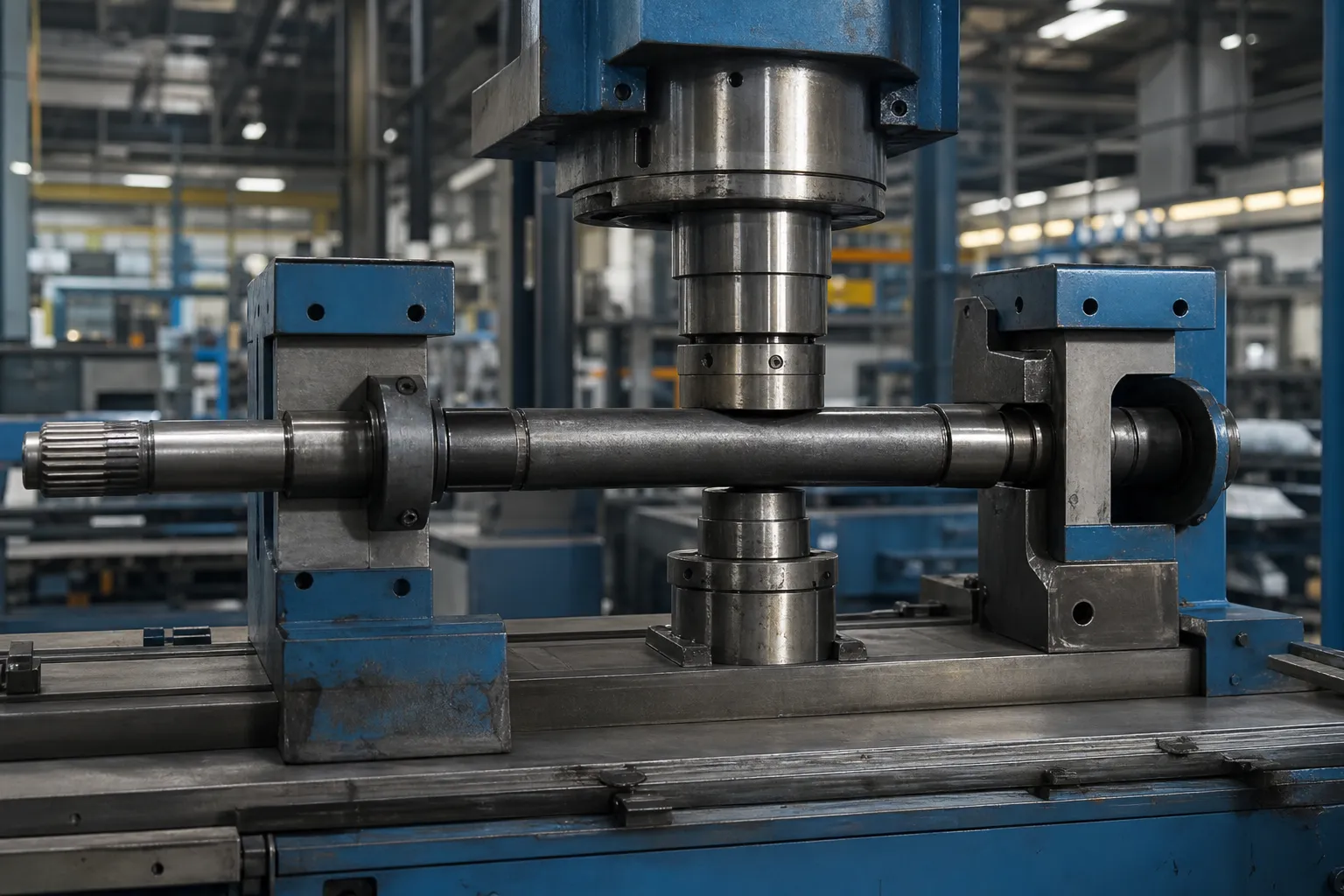
*Engineering concept illustration. It shows a possible press-correction context for a specific workpiece family, not a universal process recipe or verified local capacity.*
Define What the Process Is Correcting
The required characteristic may be straightness over a span, radial runout relative to a datum axis, lateral sweep, a local feature relationship or another controlled geometry. It must be named before a press is selected. A circularity error, surface interruption, fixture signal or intentional camber cannot be corrected as though it were the same kind of bend.
Use shaft straightness, runout and TIR when the part is rotationally inspected. Tube, profile, spring, ring and welded workpieces require their own geometry and process boundaries.
Build an Initial Error Map
The measurement plan should identify the approved datum, part orientation, axial stations, support condition, sensor method and repeat/seating check. A single midpoint reading may miss multiple bends or confuse gravity sag and fixture variation with part geometry.

*Engineering concept illustration. It illustrates a measurement map before correction; actual station locations, probes and datum must be fixed from the controlled drawing.*
| Input to freeze | Decision it supports |
|---|---|
| Drawing datum and acceptance rule | Establishes what the measurement must represent |
| Initial geometry map | Identifies candidate correction zones and interaction risk |
| Approved supports and reaction points | Prevents a force path from creating an unintended signal |
| Protected features and surface limits | Determines where contact is prohibited |
| Material and process stage | Defines possible response, springback and downstream constraints |
The Mechanics of a Point-Press Stroke
A point-press correction is a three-point bend executed on purpose. Two supports and one press point form a loading frame: the press pushes the section toward the supports, bending moment peaks at the press point and falls toward the supports, and the outer fibers at the correction location pass yield while the core of the section stays elastic. When the force is released, the elastic core tries to spring the section back while the yielded fibers hold their new shape — the permanent set is the difference, and the art of the process is delivering just enough plastic work to land the released part inside tolerance. Three consequences follow directly from this picture. The correction is local: the plastic zone concentrates around the press point, which is why error maps guide where to press rather than intuition. The process is self-limiting only if treated incrementally: a single stroke sized optimistically cannot be un-pressed. And the section’s own geometry — its stiffness variation, its transitions, its prior deformation history — modulates everything, which is why identical stroke settings do not transfer blindly between diameters, materials or lots, and why reverse-loading effects, as described for the Bauschinger effect, change the response of a part that has already been corrected once.
Support Span Is the Primary Tuning Parameter
Operators reach for force when they should reach for geometry. Moving the supports changes the correction before any force value is touched: supports spread wide give a long, gentle bending field — the same press force produces a larger deflection spread over a longer zone, appropriate for a single broad bow; supports close in around the correction point concentrate the same energy into a short, deep correction, appropriate for a local kink but harder on the surface and the section. Span also sets the mechanical advantage of the stroke: the closer the supports, the more force the same correction demands, which is why narrowing the span on a stiff section quickly reaches the machine’s or the part’s limits. Two practical rules fall out. First, choose span from the error map’s wavelength — long bows get long spans, kinks get short ones — and document the choice in the setup record, because span is a process parameter like any other. Second, treat support condition as part of the tooling: contact geometry, cleanliness and wear change the reaction path silently, and the surface-protection tooling discipline applies to supports exactly as it does to the press nose.
Choose Supports and Correction Points Together
A press point cannot be selected independently from its supports. The support spacing, section stiffness, force direction and contact geometry create the reaction path. A wrong support can make a local press look effective while transferring error elsewhere or damaging a feature.
Before a sample trial, document:
- support and reaction locations, including no-contact zones;
- correction point, force direction and permitted orientation;
- contact material, cleanliness and marking-risk controls;
- maximum incremental correction and attempt count;
- springback/release measurement plan;
- hard reject and engineering-review conditions.
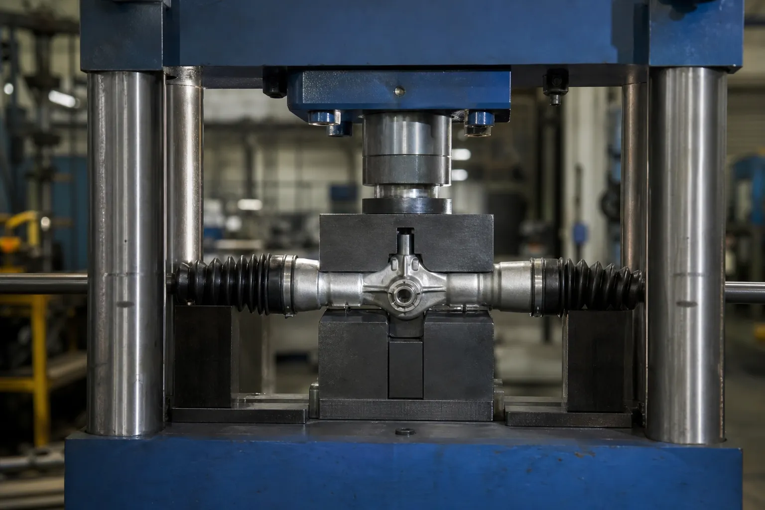
*Engineering concept illustration. It shows an incremental correction concept; it does not prescribe press load, stroke, tooling or an approved correction point for another workpiece.*
Correct Incrementally and Recheck After Release
The closed-loop sequence is:
- identify the controlled workpiece family and drawing revision;
- inspect for damage, wrong part, prohibited surface condition or out-of-scope deformation;
- load the approved datum and verify seating;
- measure the initial geometry map;
- select the permitted support and correction plan;
- apply an incremental correction within the sample-test boundary;
- fully release force, clamps and restraint;
- remeasure all required tracks and record the result;
- route the part to OK, NOK or engineering review.
The final acceptance is after release. A reading while the part remains under press force or fixture restraint cannot be used as proof of the final result.
Springback as a Process Variable, Not a Constant
Because the released shape is set by the competition between yielded fibers and the elastic core, the same stroke delivers different permanent set on parts that differ in material condition, section or prior history. That is springback as a process variable, and treating it as a fixed correction factor is how lines end up oscillating around tolerance. The discipline that handles it honestly is described for springback compensation in shaft straightening: learn the response on representative samples, correct incrementally, and re-learn when the material lot or part revision changes. A related trap deserves its own sentence: pressing a part past nominal on purpose — overshoot to pre-compensate springback — is legitimate within a validated recipe and a defined limit, but repeated overshoot-and-press-back cycles accumulate reverse-loading damage, and the correction-attempt limit exists precisely to stop that sequence before it becomes a cracking risk, per the integrity-review framework.
Reading the Data Between Strokes
Each stroke in the incremental loop is also an experiment, and the data between strokes tells the operator when to continue and when to stop. A healthy convergence shows the remaining error shrinking by a decreasing amount each stroke — the response per stroke falling as the part approaches target, which is the natural signature of a stable correction. Three patterns break that signature and each demands stopping rather than pressing harder. No progress: the geometry stops responding, meaning the process is no longer engaging the error — the correction point, support condition or part state has changed under the operator. Diminishing returns with rising effort: each stroke moves the part less while the press works harder — the section is fighting back through strain hardening, and continuing trades diminishing geometry gain for accumulating material damage. Oscillation: the part crosses nominal in alternate directions stroke by stroke — the correction rule is over-reacting, often because it was calibrated on a different response, and the fix is the recipe, not the part. Building these three stop patterns into the operating procedure converts the between-stroke data from noise into the line’s earliest quality alarm.
Know When Point Pressing Is Not the Right Route
Point pressing is not a default method for every product. Continuous wire, thin-wall tube, asymmetric profile, ring, spring, fatigue-critical or weld-sensitive part may need a different approach, dedicated tooling or a separate process review. See press versus roller straightening for the method-selection boundary.
Sample Test and Acceptance
The sample plan should include normal and worst-case incoming parts, raw before/after geometry, reseat repeatability, surface inspection, required material/feature checks, a maximum-attempt limit and correlation to the customer reference gauge. If cracks, hardness, NDT, grinding or balancing are relevant, they remain independent acceptance responsibilities.
Use straightening sample test and acceptance to define the evidence required before a production claim or FAT/SAT decision.
FAQ
Can point pressing guarantee a specific accuracy?
No. The attainable result depends on the workpiece, datum, material state, support, contact zones, sample response and agreed inspection method.
Is the highest indicator point always the correction point?
No. The correction point must be chosen from the geometry map and approved reaction path, not from an isolated visual or indicator observation.
Can a press repair a crack or replace NDT?
No. Straightening does not repair material defects and does not replace qualified inspection processes.
Why does the same press stroke move two identical-looking parts differently?
Because released geometry depends on material condition, section detail and prior deformation, not on appearance. Different lots, heat-treatment states or a previous correction cycle all change the plastic-versus-elastic balance the stroke works against. The remedy is learning the response per family on samples and re-checking it when lots change.
When should supports be moved closer together?
When the error map shows a short, local kink rather than a broad bow. A narrow span concentrates the correction where the error lives; a broad span spreads it. The span choice belongs in the documented setup, because it changes both the correction shape and the force the part must carry.
What does it mean when a part stops responding to corrections?
The process is no longer engaging the error — a no-progress condition. Causes range from a changed correction point to a setup or part-state shift, and the defined response is to stop and route the part to review, not to increase force. Continuing to press spends the part’s deformation budget on nothing.
Straightening Before vs After Grinding
No independent canonical page is maintained for straightening before vs after grinding because industrial exact-match demand is thin. Stage sequencing, stock allowance and datum transfer belong in the forged-bar, point-press and multi-point process pages. Confirm whether grinding removes material that would invalidate an earlier straightness reading before locking the production route.
Force鈥揇isplacement Curves in Straightening
A dedicated page for straightening force displacement curve guide is not maintained without validated query demand. Force鈥搒troke interpretation, safe limits and process stop conditions are explained in the point-press, multi-point and crack-detection pages. Any curve-based alarm must be validated on representative parts rather than copied from another material family.
Point-press work lives or dies by stroke control – read why over-correction cracks parts before you size a machine, then use the straightener selection walkthrough to match press concepts to your part family.