
Selecting a straightener should start with the required geometry and acceptance method, not with a machine label. A shaft, a thin-wall tube and an asymmetric profile can all look bent, but they may require different datums, measurement tracks, supports, contact zones and correction methods. A machine comparison that ignores those differences can produce an attractive quotation without a defensible sample-test plan.
This guide is a buyer and engineering framework. It does not claim that StraighteningTech offers every machine type, workpiece envelope, accuracy, force, automation level or line interface. A final configuration requires the drawing, samples, inspection method and validated capability evidence.

*Engineering concept illustration. It shows a workpiece-to-method decision process, not a product catalogue or proof that every route is available.*
Start With the Required Characteristic and Datum
The first question is what must be accepted: centerline straightness, runout, TIR, coaxial relation, bow, lateral sweep, twist, ovality, wall condition or another controlled feature. These terms are not interchangeable. The drawing must identify the reference, support condition, measuring span, orientation and released-state decision rule.
| Workpiece family | Typical selection issue | Do not assume |
|---|---|---|
| Shaft | Functional axis, journal datum, runout map and local section changes | Every shaft can use the same point-press sequence |
| Tube | Centerline, ovality, wall integrity and collapse risk | An outside reading proves the bore/wall is acceptable |
| Profile / rail | Bow, sweep, twist, asymmetric section and face protection | A round-bar roller arrangement fits a profile |
For measurement terminology, start with shaft straightness, runout and TIR and tube ovality versus centerline straightness.
Map the Error Before Choosing the Method
An initial geometry map identifies whether the deviation is global, local, one-plane, multi-plane, angular, section-related or caused by a support/fixture signal. It should be captured with the proposed datum and checked through reseating or an agreed repeat method. A reading under an unstable support condition is not a reliable correction target.
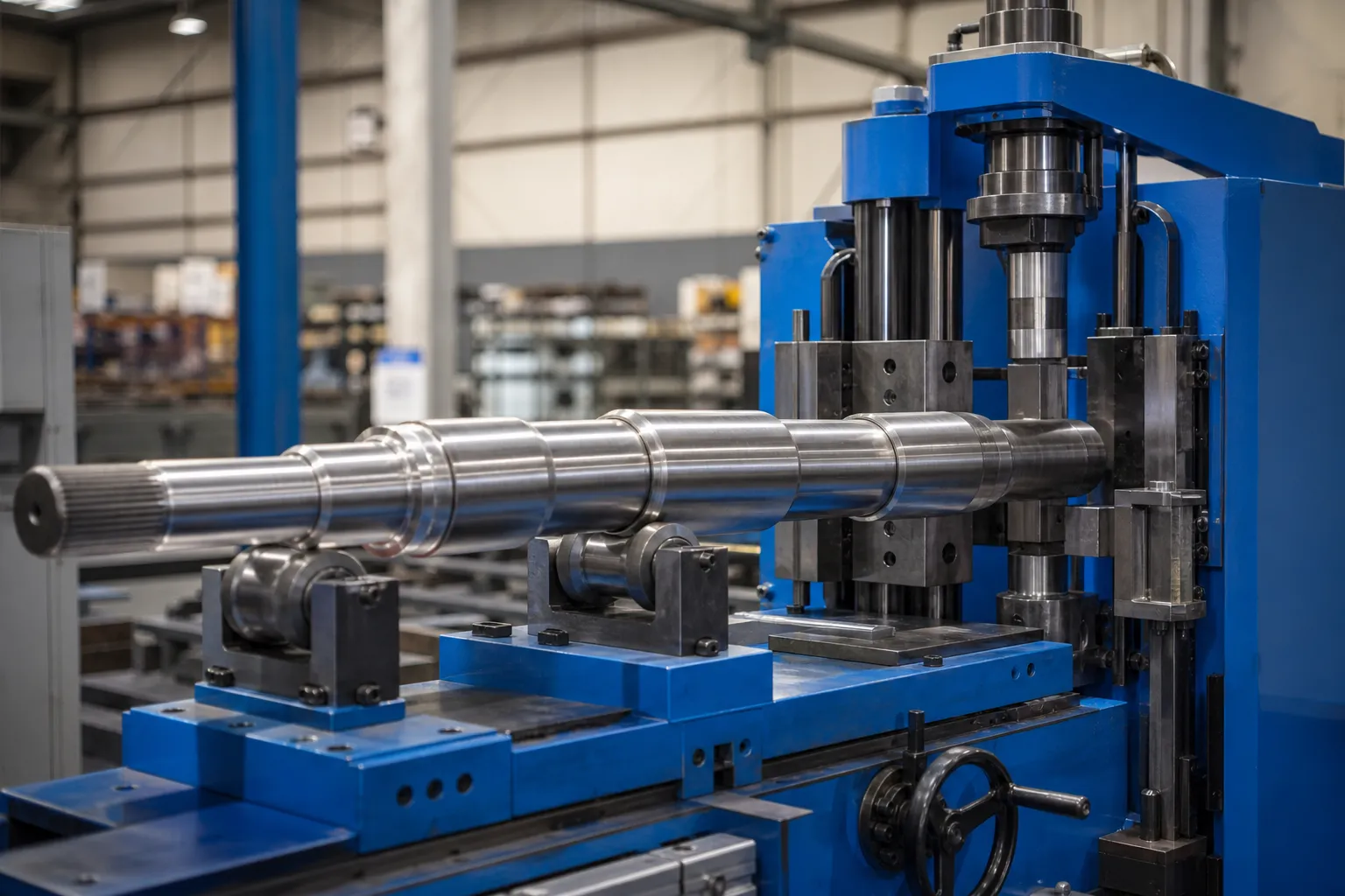
*Engineering concept illustration. It shows a candidate measurement-and-correction cell; actual sensors, supports, force path and automation require workpiece-specific validation.*
The Specification Package That Gets Accurate Quotes
The quality of the quotations a buyer receives tracks the quality of the specification package sent out, and the package is small enough to be worth assembling properly. Its items are: the drawing with the controlled characteristic named and its datum identified — not only a tolerance number floating free of a reference; the material and its process stage, because a hardened part and an annealed one are different correction problems wearing the same geometry; the incoming error distribution from real parts, because a machine sized for gentle bows will not suddenly handle the worst lot of the year; the acceptance method as the customer runs it, including support condition and released-state rule; the protected zones and surface classes; the production mix and changeover frequency; and representative samples the supplier can actually test. Buyers who send this receive differentiated engineering responses. Buyers who send a diameter and a target accuracy receive brochure round-trips — and discover the gap between the two at commissioning, which is the most expensive place to hold the conversation.
Sizing Force, Stroke and Envelope Without Overbuying
Three machine dimensions carry most of the sizing decisions, and each is set by workpiece physics rather than by ambition. Correction force follows from the section modulus of the stiffest part family and its yield condition: enough force to plastically bend the worst section, with working margin so the machine is not permanently at its ceiling — but force beyond the family’s need buys nothing except a heavier, stiffer, more expensive machine that may also be coarser in control at the small end of the range. Stroke and daylight follow from the part family’s diameters, the tooling heights and the handling concept. Work envelope and loading height follow from part length and mass, because supporting a long part safely is part of the machine’s job, not an afterthought. The classical overbuying failure is specifying for a hypothetical giant part that never materializes and then running a family the machine barely registers; the underbuying failure is sizing to the average part and meeting the worst lot with no headroom. Both are avoided the same way: the sample test on the actual family, at its actual worst, before the configuration is frozen — the same evidence rule that governs the automation boundary.
Evaluate Contact and Section Integrity
The candidate machine must create an approved reaction path without damaging protected features. Review accessible support zones, permissible correction points, surface/coating requirements, length and mass handling, section transitions, wall thickness, bore condition, seam orientation and downstream operations.
| Selection input | Why it matters |
|---|---|
| Contact and no-contact zones | Determines whether a support or correction route is even permissible |
| Section stiffness and wall condition | Changes response and local-damage risk |
| Incoming error distribution | Defines whether a local or continuous method can be evaluated |
| Manufacturing stage | Determines surface/allowance restrictions and the next process interface |
| Production mix | Affects changeover, recipe control and handling validation |
Compare Candidate Routes Conditionally
Point pressing can be evaluated where a discrete geometry map, support path and approved correction points exist. Roller or continuous straightening can be evaluated for compatible, sufficiently consistent sections. Stretch, torsion or specialised routes may be candidates only when the workpiece, clamping, material and validation requirements support them. No method is a default guarantee.
See press versus roller straightening for the method boundary and point-press straightening for a closed-loop local-correction framework.
Where Selections Go Wrong
Failed selections cluster into recognizable patterns, and naming them is cheaper than living one. Choosing by machine label: buying a “shaft straightener” for a shaft-shaped part whose datum, section transitions and acceptance method actually demand something else — the label describes the brochure, not the fit. Accepting accuracy from a table: a published accuracy figure is a machine attribute under stated conditions; the delivered result on your family, your gauges and your incoming distribution is established by the sample test, nothing else. Forgetting the exception path: the machine is selected on how it handles good parts, while production success also depends on how it detects, routes and records the bad ones — the NOK routing discipline deserves a line in the specification, not a discovery during ramp-up. Leaving acceptance undefined: two parties can share a number and disagree about its meaning unless the support condition, gauge and released-state rule are written down, which is why the FAT framework freezes those inputs before testing. And ignoring changeover: in a high-mix shop, the route that wins on paper for one family can lose the year through setup time, first-article validation burden and recipe control across many.
Changeover Economics in a High-Mix Shop
For shops running many part families in small lots, changeover behavior deserves evaluation as a first-class selection criterion, alongside geometry and force. The questions are concrete. What physically changes between families — supports, press tooling, sensor positions — and how is each change identified so an old setup cannot run silently on a new part? How long does a validated changeover take, and who performs it? What requalification does the quality system demand after a changeover: a first-article check, a reseat verification, or a fuller sample? Machines designed for mix answer these with identified tooling, recipe management and guided changeover sequences; machines designed for high-volume single families answer them with engineering hours. Neither answer is wrong — but the buyer should know which one they are purchasing before the second family arrives at the dock, and the honest place to test changeover is during the acceptance test, where a family switch can be demonstrated and timed under witness.
Define the Automation Boundary
“Automatic” should be decomposed into loading, identification, orientation, measurement, correction, handling, recipe management, traceability and exception routing. A system may automate some steps while retaining manual fixtures, engineering approval or customer-gauge verification. Do not use an automation label as a proxy for throughput, accuracy or labor savings.
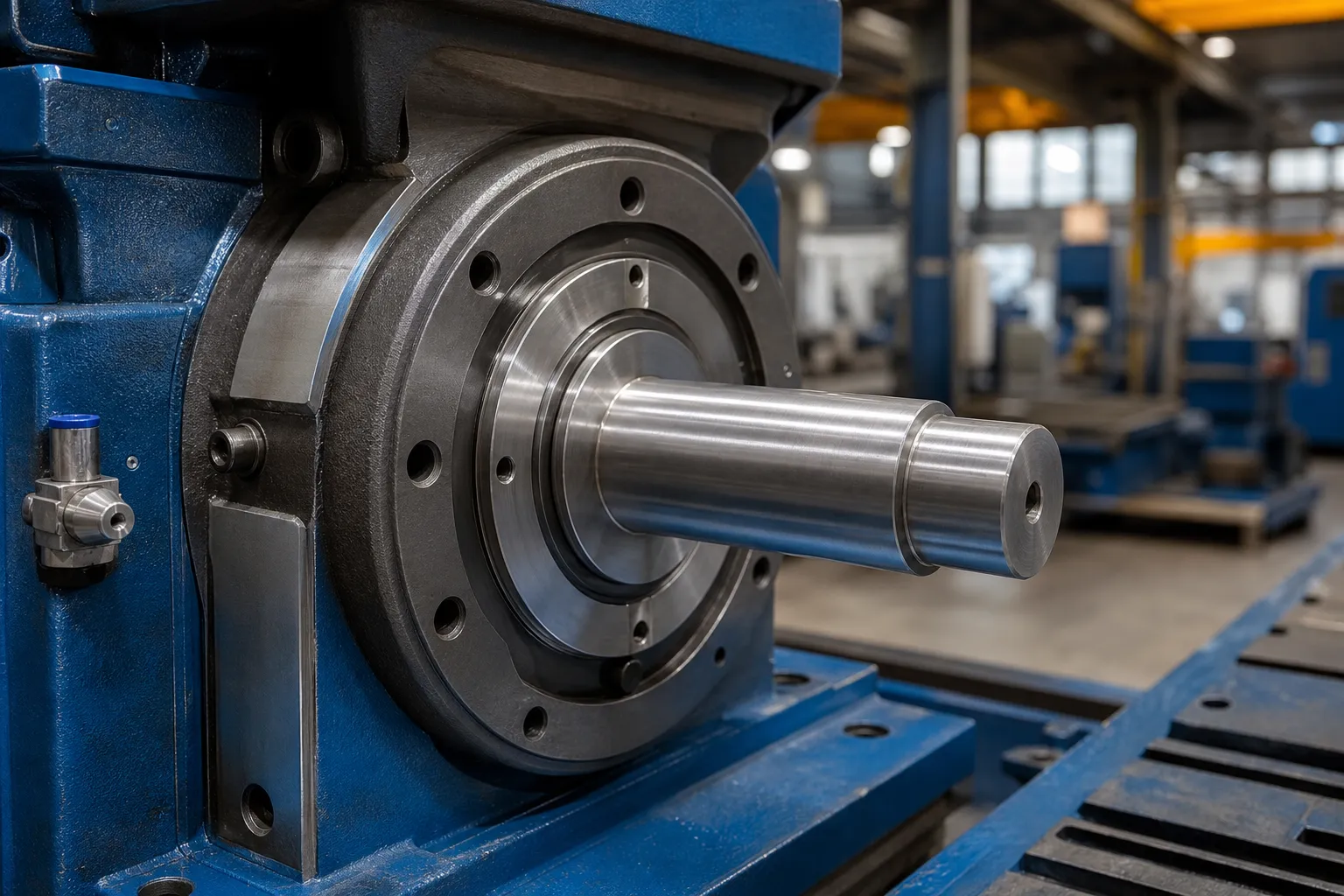
*Engineering concept illustration. It emphasizes released-part verification; it is not a customer acceptance report or a guaranteed performance result.*
Make the Sample Test the Selection Gate
The selection should close with representative normal and worst-case samples, a controlled drawing, agreed datum/gauge, raw before-and-after readings, released-state remeasurement, surface/section checks, maximum correction-attempt limits and a defined NOK route. Any promised accuracy, cycle time, handling rate or automation scope belongs only after that evidence is complete.
Use straightening sample test and acceptance to structure the trial, FAT and SAT evidence.
Information Needed for a Straightener Selection Review
Provide the workpiece drawing and variants, material and manufacturing stage, length/section/wall information, incoming geometry data, functional datum, protected zones, reference measurement method, production target, handling constraints and representative samples. StraighteningTech can then assess candidate measurement, support and correction architecture and identify the evidence needed before proposing a machine configuration.
FAQ
Can one machine process shafts, tubes and profiles?
Possibly for a defined and validated workpiece range, but not because all three are called “straightening.” The datum, section and contact route must be reviewed.
Is a faster machine automatically the better choice?
No. Throughput has value only after geometry, surface, measurement and exception handling meet the agreed acceptance method.
Can a product page replace a sample test?
No. Product descriptions establish a category; a representative sample test establishes whether a specific workpiece family can be accepted.
How do I know if a machine is oversized for my parts?
When the family consistently occupies the bottom of the machine’s force and range scale. A machine with large margin above the stiffest family’s need is heavier, coarser in control at the small end, and more expensive than a right-sized configuration — and the family’s correction precision can suffer for it. The fix is sizing from the actual section modulus and worst-case incoming error, verified by sample test.
What should changeover look like in the acceptance test?
A witnessed family switch: old tooling out, new tooling in and identified, recipe selected under version control, first-article part measured and dispositioned, with the elapsed time and each verification step on record. If changeover matters to the shop’s economics, it belongs in the FAT scope rather than in a verbal assurance.
Is the published accuracy of a straightener what my parts will achieve?
It is what the machine achieves under its stated reference conditions. What your parts achieve depends on their geometry, material state, incoming error, your gauges and your acceptance method. The bridge between the two is the sample test on representative and worst-case parts — the only evidence that converts a specification into a defensible expectation.