
Tube ovality and centerline straightness are different geometric conditions. Ovality concerns the shape of a cross-section; centerline straightness concerns the path of the tube along its length. A tube can have acceptable centerline geometry but be out of round at one station, or it can be round at each measured section while its centerline bows across a long span. Treating these conditions as one “straightness” value can lead to a wrong process decision.
This guide is a measurement and acceptance framework. It does not claim a StraighteningTech tube range, wall capability, gauge, sensor, tolerance or validated correction process. Final requirements must come from the controlled drawing, reference method and representative samples.

*Engineering concept illustration. It depicts a tube-straightening process context, not proof that a specific tube family or wall condition can be processed.*
Define Each Characteristic Before Measuring Either
Ovality is a per-station property: every measured cross-section has its own value, and a tube inspected at twelve stations has twelve ovality values that can differ. Centerline straightness is a whole-length property: it is derived from the path traced by the successive centers of those cross-sections. The two characteristics do not merely describe different defects — they live at different levels of the measurement chain, and the higher level is computed from the lower one.
That dependency is the hidden coupling. A centerline is not measured directly; it is computed, station by station, from sections that are never perfectly round. Whichever rule converts a measured section into a single center point — the average of two diameters, a least-squares circle center, a minimum-zone circle center, or the center a two-point gauge happens to report — becomes part of the straightness definition. Two inspection methods can therefore disagree about the centerline of the same physical tube while each is internally consistent, because they embedded different center-finding rules.
The acceptance documents should state, for each characteristic: the formula (diameter-based ovality, radial-deviation-based ovality, or a full form tolerance), the center-finding rule feeding the centerline calculation, and the station set over which each value applies. A single “straightness OK” record that does not say which rules produced it is not transferable between supplier and customer gauges.
Measure Cross-Section and Lengthwise Geometry With Appropriate Supports
Support positions can affect the apparent centerline through sag; clamping can affect a thin-wall section; probe contact can affect surface or wall response. The procedure should therefore define the conditions for each characteristic and repeat/reseat checks where needed.
| Measurement control | Why it matters |
|---|---|
| Cross-section station and orientation | Ovality can vary along length and around the circumference |
| Longitudinal span and supports | Centerline readings can include gravity and fixture effects |
| Datum and end condition | Determines whether the result relates to the intended function |
| Contact or optical method | Can introduce different surface, access and uncertainty limits |
| Released condition | Prevents temporary restraint from being reported as final geometry |
Support Spacing Filters the Centerline Signal
On a measured span, supports act as a mechanical filter for the centerline reading: bending content with a wavelength shorter than the support spacing is partially suppressed by the stiffened sections, while longer-wavelength bow passes into the reading. The same tube can therefore report different bow on a short fixture span than on a long one without either reading being wrong. The support span is not a setup convenience — it is part of the straightness definition, and it must match, or be explicitly correlated to, the span used by the customer gauge.
Station spacing plays the analogous role in the sampling domain. Widely spaced stations under-sample the centerline path and can miss a local kink between stations; very dense stations begin to mix surface and wall-thickness variation into the computed axis. The sampling plan should state where stations sit — not only how many — because the informative stations are the support points, the clamping points, the tube ends and the neighborhoods of expected bend peaks.
On thin-wall tubes the supports carry a second, unwanted effect: support reaction can ovalize the section locally, so the ovality measured at a support station includes a measurement-induced contribution. Comparing readings at supported stations against readings taken just outside the support influence is a cheap check for this; where the difference is significant, the ovality acceptance must be evaluated at defined free stations. For the loaded-versus-released distinction in final acceptance, see loaded vs released straightness measurement.
Do Not Correct One Error and Assume the Other Is Solved
A correction process intended to reduce bow may change ovality or wall condition. A process intended to improve section form may not establish centerline straightness. The sample plan must define which geometry is controlled, which secondary characteristics are checked, where contact is permitted and when an independent process is required.
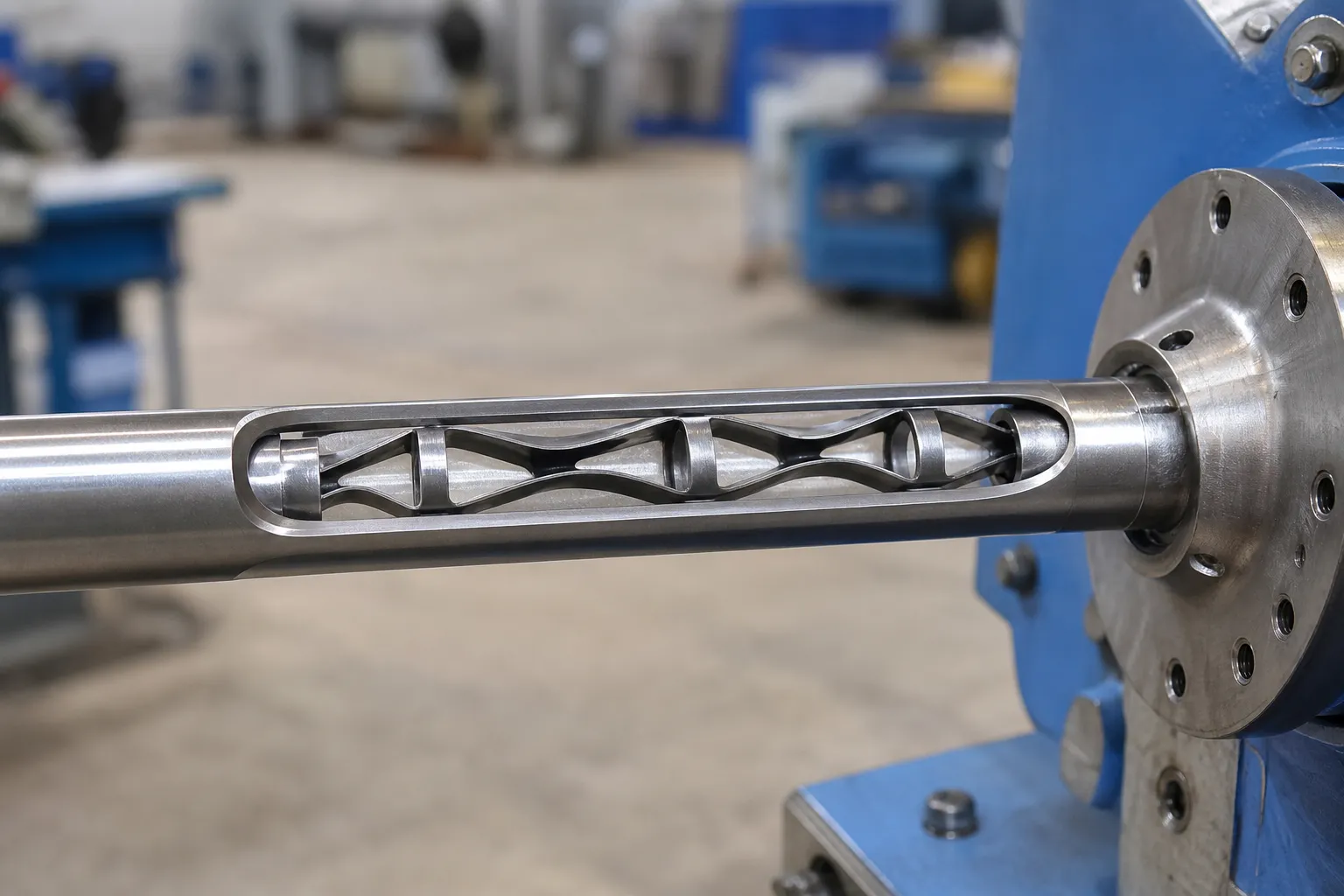
*Engineering concept illustration. It presents internal support as a candidate engineering question; it is not a claim that internal tooling is standard or appropriate for every tube.*
For non-round hollow sections, see square and rectangular tube straightening. For hollow rotating parts, see thin-wall hollow shaft straightening.
Separate the Two Signals Before Accepting Either Reading
The two characteristics contaminate each other's measurements in specific, diagnosable ways. In a rotating single-probe trace at one station, the radial signal contains at least the local form error of the section and the offset of the section center from the rotation axis. Ovality-dominated form error appears primarily as a second harmonic — the trace repeats twice per revolution, with the ovality major axis setting the phase. A center offset appears as a first harmonic — one bump per revolution. Within a single trace the two are separable in principle, but the first harmonic itself is ambiguous: a genuine bend and a seating or chucking offset produce the same single-station signature. The discriminators live outside the single trace. Across stations, a bend changes amplitude with longitudinal position and follows the bend plane, while a seating offset keeps a constant amplitude and a phase locked to the rotation axis. That multi-station logic, together with the harmonic fingerprints of lobing and datum effects, is developed in roundness vs bend in rotating measurement.
The contamination also runs the other way. A probe scanned along the tube reads the local surface, not the axis: a tube that is straight on its centerline but drifting in ovality orientation along its length produces a lengthwise trace that looks like bow. A practical two-scan check costs little: scan the length in one direction, then in the orthogonal direction — by rotating the tube ninety degrees against the same probe, or by using a second probe at right angles. Compare the two traces. A centerline bow decomposes into the two directions as projections of one vector: the two traces are similar in shape and same in sign, each a scaled copy of the other. Section form does the opposite: where the ovality major axis lies in the first scan direction it lies across it in the second, so a peak in one trace corresponds to a valley in the other. Traces that are same-shape-same-sign nominate a bend; traces that are opposite-sign at particular stations nominate form and wall variation. Only the first category should go to a correction decision.
Wall-thickness eccentricity adds a third layer on drawn or rolled tube: the outside surface and the bore are not concentric, so a centerline computed from outside-diameter measurements and one computed from bore measurements will not coincide. Neither is wrong; they answer different functional questions. Which one governs acceptance must follow the function of the part in its assembly — and the drawing, not whichever gauge happens to be available, defines it. Thin-wall behavior during correction has its own failure modes, covered in thin-wall tube straightening without collapse.
Build a Customer-Gauge Correlation Plan
The trial should use representative normal and worst-case tubes, raw readings for both characteristics, agreed support and release conditions, repeat setup, surface/wall checks, and comparison to the customer gauge. The record should state whether a reading is a machine process value, a customer acceptance value or a correlated result.
Use machine gauge versus customer gauge correlation and straightening sample test and acceptance to define the evidence package.
Run Two Separate Acceptance Chains, Not One
Because the definitions, supports and failure modes differ, ovality and centerline straightness each need their own chain from drawing language to signed record. Collapsing both into one generic “geometry OK” leaves every link below ambiguous:
| Chain link | Ovality chain | Centerline chain |
|---|---|---|
| Characteristic and formula | Which deviation rule, applied per station | Which span governs, and which center-finding rule feeds the path |
| Reference method | Section measurement at defined stations | Lengthwise scan or rotating trace on defined supports |
| Support and release | Free stations distinguished from supported stations | Span defined; sag and clamping effects addressed or correlated |
| Sampling | Station positions fixed by the specification, not by convenience | Station spacing short enough to resolve the shortest expected bend |
| Gauge capability | Repeatability proven against within-part form variation | Repeatability proven against part-to-part and setup variation |
| Correlation | Machine gauge vs customer gauge on the same sections | Machine gauge vs customer gauge on the same span and supports |
| Record | Per-station values with rule and station identity | Path result with support span and filtering stated |
Each link is a place the chain silently breaks. An unstated formula makes two gauges' numbers incomparable. A support condition defined at the machine but not at the customer builds a systematic offset into every correlation attempt. An unspecified station set makes the verdict depend on where the operator happened to measure. And an unproven gauge capability converts measurement noise into apparent process drift, which the correction loop then chases. Validating the measurement system before trusting any of these numbers is covered in gage R&R for straightening lines.
FAQ
Can a tube be straight but out of round?
Yes. Centerline straightness and ovality are different conditions and require separate measurement. In practice the two belong in the same inspection record but under different characteristic numbers, each with its own formula, station set and gauge correlation.
Does a round cross-section prove the tube is straight over its length?
No. A tube may be round at measured sections while its centerline has bow or sweep. A lengthwise scan reads the surface rather than the axis, so the orthogonal two-scan comparison above is what keeps form effects out of the straightness verdict.
Can a correction process guarantee both results?
Not without workpiece-specific validation. The process must measure and verify every characteristic required by the drawing. In particular, a process validated for bow says nothing about its effect on section form at contacts, supports and free stations — those need their own before-and-after readings.
How can we tell whether a straightness reading is contaminated by ovality?
Repeat the lengthwise scan in the orthogonal direction and compare the traces. Same shape and same sign across the two scans is the signature of a centerline bow; opposite sign at particular stations points to section form or wall variation. Rotating single-station traces add a second test: a bend changes amplitude between stations, while a seating offset does not.
Does ovality need to be measured at every cross-section?
Only the specification can answer that. What the acceptance plan must guarantee is that the station set is fixed in advance — typically including supports, clamps, ends and the neighborhoods of bend peaks — so the verdict does not depend on where an operator happened to check.

*Engineering concept illustration.*