
Thin-wall tubes can be bent, oval, locally dented or twisted at the same time. A process that improves the tube centerline can still fail if it collapses the section, wrinkles the wall, marks the surface or damages a weld seam.
A thin-wall tube straightening solution must therefore control both global geometry and local cross-section integrity. It begins with the drawing, tube construction and manufacturing stage—not with a generic press-force or roller setting.
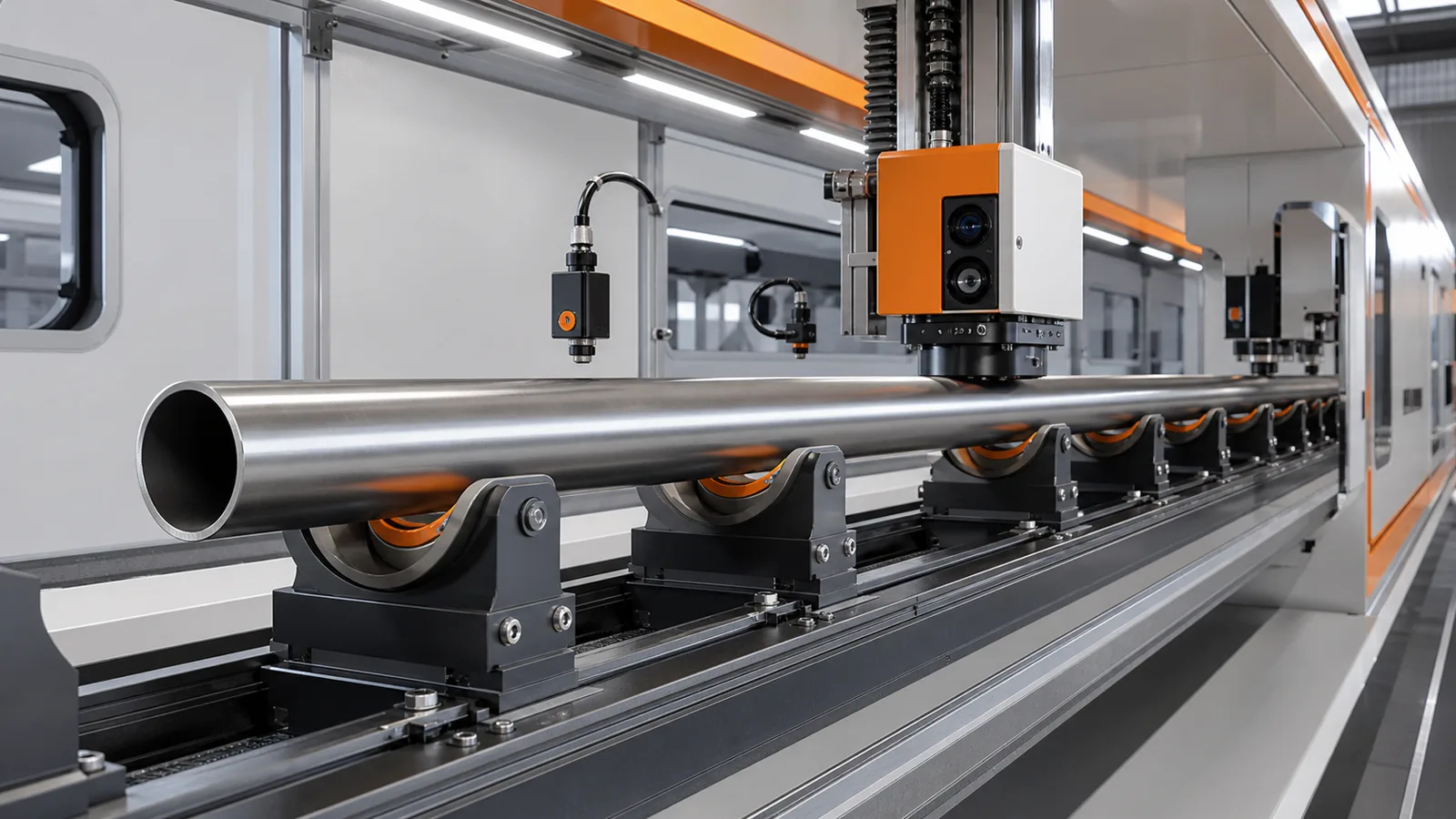
This is an engineering concept illustration, not a customer-site photograph. Actual supports, sensors and correction tooling depend on tube diameter, wall thickness, material, section and sample tests.
Why Thin-Wall Tubes Are Different
| Tube Property | Straightening Risk | Engineering Response |
|---|---|---|
| Hollow section | External correction can flatten or collapse the tube | Control contact geometry, pressure and internal support need |
| Small wall thickness relative to diameter | Local buckling and wrinkling can occur before useful correction | Validate strain and support span on worst-case samples |
| Existing ovality | Rotation measurement can confuse form error with bend | Measure centerline and section shape separately |
| Welded seam | Seam stiffness and damage risk can vary by angular position | Detect/index seam and define protected sectors |
| Finished outer surface | Rollers or press tools can create dents and witness marks | Approve contact material, width, cleanliness and surface criteria |
| Long flexible length | Sag changes the measured curve | Freeze support span, orientation and sag treatment |
| Bent/tapered/stepped tube | Straight rotation and uniform tooling may not apply | Use section-specific supports and station maps |
| Open ends | End sections deform more easily | Define minimum usable end distance and end support |
The project should never use “straightness achieved” as the only success criterion. Cross-section and surface condition must remain inside the agreed limits.
Separate the Defects Before Selecting a Method
Centerline Bend
The tube axis or centerline deviates along its length. This is the primary target of ordinary bending straightening.
Ovality and Local Flattening
The cross-section is no longer sufficiently round. Ovality can pre-exist, arise from clamping or be created by straightening contact.
Local Dent or Collapse
A concentrated load produces a local inward deformation. Improving centerline bend does not automatically remove this damage.
Wrinkling or Buckling
The compression side of a thin wall can form waves or a local buckle when correction strain is too high or insufficiently supported.
Twist
Round tubes may hide twist unless they contain features, seams, holes or attached brackets. Rectangular and shaped tubes require explicit torsion measurement and a different correction strategy.
Weld Distortion
Longitudinal seams, end welds or attached fittings can introduce asymmetric deformation and local strength differences. Welded assemblies should not be treated as uniform raw tube.
Freeze Tube Construction and Process Stage
The solution must identify whether the workpiece is:
- seamless or longitudinally welded;
- round, oval, square, rectangular or another profile;
- straight raw tube, cut-to-length blank or formed part;
- annealed, heat-treated, coated, polished or otherwise finished;
- empty, fitted with internal components or part of a welded assembly;
- before or after machining, bending, welding or surface treatment.
Straightening a raw tube before finishing has different surface and allowance rules from correcting a polished automotive tube or a welded cooling manifold. Later processing can reintroduce distortion, so the route may require more than one controlled geometry check.
Define Global and Local Acceptance Together
| Characteristic | What It Controls | Why It Must Be Separate |
|---|---|---|
| Axis/centerline straightness | Global tube path | Does not prove the cross-section stayed round |
| Circular/total runout | Rotational variation relative to a datum | Includes reference and section-form effects |
| Outside diameter | Local size | Can change during flattening or expansion |
| Ovality/roundness | Cross-section shape | Direct collapse indicator for round tubes |
| Wall thickness | Section strength and forming response | May vary around welded or drawn tube |
| Surface condition | Dents, scratches, coating or cosmetic marks | Independent of centerline result |
| Seam condition | Weld integrity and location | Can control orientation and correction limits |
| Twist | Angular change along shaped/featured tube | Not captured by one radial probe |
The drawing and customer gauge must define stations, datum, support condition, filters and decision rules. Review Shaft Straightness vs Runout vs TIR before interpreting a rotating indicator signal as tube straightness.
Measure Centerline and Ovality Separately
A single contact probe on the outside diameter cannot always distinguish a bent but round tube from a straight but oval tube. Multiple angular readings, opposing sensors, diameter scans or a suitable non-contact system may be required.
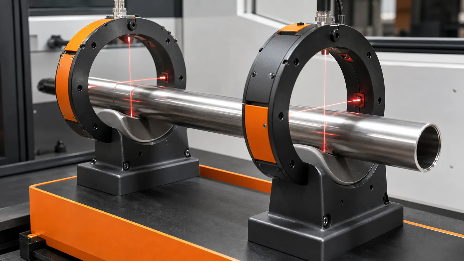
This engineering concept illustration shows non-contact centerline and diameter measurement. It does not prescribe optical sensors for every tube.
| Measurement Element | Project Definition |
|---|---|
| Datum/reference | Ends, journals, fittings, mathematical axis or customer fixture |
| Axial stations | Global curve points plus high-risk local sections |
| Angular coverage | Enough directions to separate bend and ovality |
| Support plan | Number, span, height and contact pressure |
| Seam indexing | Seam angle at measurement and correction stations |
| Probe method | Contact force or non-contact range/resolution |
| End exclusion | Minimum distance from unsupported/open ends |
| Released condition | Measurement only after external/internal correction load is removed |
For non-round tube, the system may need multiple faces, edges or section-specific coordinates rather than simple rotational runout.
Support the Tube Without Creating the Defect
Supports must hold and move the tube while keeping contact pressure below the validated local deformation limit.
Important variables include:
- saddle radius and conformity to the actual OD;
- roller width and edge radius;
- sleeve/pad material and embedded-particle risk;
- support span and intermediate support positions;
- tube rotation or axial-feed force;
- clamping pressure and grip length;
- open-end support and minimum contact distance;
- weld-seam angle relative to contacts;
- cleaning and tooling-inspection frequency.
A soft pad can still dent a tube if the contact area is too small or contamination is trapped beneath it. Tooling must be validated on the minimum wall thickness and weakest included material condition.
Press Straightening vs Roller Straightening
| Route | Strong Starting Fit | Main Thin-Wall Risk |
|---|---|---|
| Localized press straightening | Discrete bend zones, feature-rich parts, low/medium mix | Local flattening, denting and compression-side wrinkle |
| Multi-roll/continuous straightening | Long uniform tubes with distributed curvature | Repeated contact, ovality growth, end effects and surface marking |
| Moving-frame correction | Long tubes where moving the part is difficult | Support transitions and station correlation |
| Internal-support-assisted correction | High collapse risk at known local zones | Mandrel insertion, fit, friction and removal |
| Hybrid process | Pre-straighten stock then targeted final correction | Clear acceptance and responsibility at each stage |
Use Press Straightening vs Roller Straightening for the general method decision. Thin-wall tube selection adds section-stability and surface constraints.
Internal Support: Option, Not Default
An internal mandrel, expandable support, plug or local backing device can reduce collapse at the correction zone. It also introduces new risks.
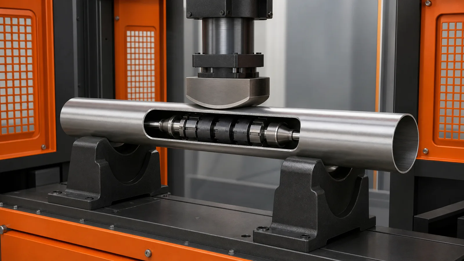
This cutaway engineering concept illustrates one possible internal-support arrangement. It is not a universal production design.
| Internal-Support Question | Why It Matters |
|---|---|
| Can the device enter and reach the correction zone? | Bends, length, fittings and closed ends may block access |
| What is the support clearance? | Too loose gives little support; too tight can score or jam |
| How is it positioned? | The internal support must align with the external load zone |
| Is it fixed or expandable? | Expansion force can itself change diameter/ovality |
| What is the contact material? | Internal surface scratches or contamination may be unacceptable |
| How is it removed? | Springback, burrs or deformation can trap the device |
| Can several stations be corrected? | Moving the support affects cycle and control complexity |
| How is internal condition inspected? | Damage may not be visible from outside |
Alternative approaches can include broader external tooling, lower incremental correction, hydro/pneumatic support where appropriate, or moving the straightening operation to an earlier process stage. Each requires its own safety and validation plan.
Weld Seam and Feature Indexing
For welded tubes, seam position can affect stiffness, measurement and damage risk. The recipe should define whether the seam is:
- detected automatically or oriented manually;
- permitted under a support or press tool;
- excluded from high-strain correction sectors;
- measured for local profile or integrity;
- tracked through the entire cycle.
Holes, slots, beads, brackets, flares, swages and end fittings also change local stiffness. An ordinary OD sensor or press tool should not cross these features without a defined method.
Controlled Correction and Springback
Localized correction should use a validated span and broad conforming contacts. The machine applies only enough controlled over-bend to obtain permanent correction after release.
The recipe should bound:
- support and correction coordinates;
- seam/feature angular orientation;
- maximum force, stroke and loaded displacement;
- maximum section deformation during loading;
- correction increment and attempt count;
- reverse-correction or oscillation rules;
- internal-support state and position;
- post-release straightness, ovality and surface checks.
Final acceptance must be measured after the external load and any internal expansion force are fully released. See Springback Compensation in Shaft Straightening for bounded iteration and stop logic.
A Defensible Automatic Cycle
- Identify tube family, drawing, construction and process-stage recipe.
- Confirm diameter/section, wall range, material and seam/feature condition.
- Clean the tube and inspect external/internal support tooling.
- Load on broad validated supports and locate the tube axially.
- Detect or index seam and prohibited features where required.
- Measure centerline and cross-section characteristics at agreed stations.
- Separate sag, ovality and local dents from correctable global bend.
- Select the approved correction method, span and optional internal support.
- Apply bounded correction while monitoring force/stroke and section risk.
- Fully release external/internal loads and restore the measurement condition.
- Remeasure centerline, ovality/section and surface/seam criteria.
- Record results and route to OK, recheck, secondary operation or NOK.
Round, Rectangular and Formed Thin-Wall Tubes
| Tube Family | Additional Control |
|---|---|
| Round seamless tube | Bend/ovality separation and end collapse |
| Longitudinally welded round tube | Seam indexing and integrity |
| Square/rectangular tube | Face flatness, corner radii, twist and wall buckling |
| Oval/formed section | Section-specific supports and measurement model |
| Bent tube assembly | 3D datum, tangent/angle and local bend geometry |
| Tube with fittings | Grip/feature protection and access for internal support |
| Multi-channel/extruded tube | Internal webs, torsion and local crush behavior |
| Coated/polished tube | Surface contact and cosmetic standard |
These families should not share an unvalidated universal recipe.
Machine and Data Modules
| Module | Project Definition |
|---|---|
| Loading/transfer | Manual, conveyor, gantry or robot; anti-sag handling |
| Part identification | Section, wall/material family and wrong-recipe prevention |
| Seam/feature detection | Camera, sensor, fixture or manual index |
| Support line | Saddle/roller geometry, span, setup and wear monitoring |
| Measurement | Centerline, diameter/ovality, twist and local-section stations |
| Correction | Press, rollers, moving frame or hybrid process |
| Internal support | Type, positioning, expansion, insertion and removal |
| Surface/seam inspection | External and internal criteria after correction |
| Traceability | Initial map, correction history, final map and reject reason |
| Quality interface | Customer gauge correlation and reference-master checks |
Sample Test and Acceptance Matrix
| Test Group | Representative Samples | Evidence Required |
|---|---|---|
| Diameter/wall range | Largest diameter with thinnest wall plus boundaries | Collapse and tooling envelope |
| Material/condition | Softest, strongest and finished states | Springback, wrinkle and surface response |
| Welded/seam variants | Seam angles and weld batches | Indexing and integrity result |
| Length/bend range | Shortest/longest, good/borderline/worst incoming | Support, sag and correction map |
| Cross-section | Round plus every approved shaped family | Dedicated gauge/tooling result |
| End/features | Open ends, holes, fittings and formed zones | Exclusion and local support rules |
| Internal support | Insertion/position/removal extremes | No jam or internal damage |
| Gauge correlation | Same parts on machine and customer method | Offset, repeatability and decision agreement |
Use the Straightening Sample Test and Acceptance Guide to define feasibility, FAT and SAT evidence.
Information Required for a Thin-Wall Tube Proposal
Please provide:
- complete tube/assembly drawing and revision;
- seamless/welded construction and seam specification;
- material, temper/heat treatment and process stage;
- round or shaped section, OD/width/height, wall thickness and length range;
- bend, straightness, runout, ovality, diameter, twist and surface requirements;
- datum/reference, measuring stations and customer fixture;
- incoming bend/ovality/dent distribution and representative rejects;
- holes, slots, welds, fittings, bends, flares and prohibited zones;
- approved external and internal contact surfaces;
- cosmetic, coating, seam and internal-surface acceptance criteria;
- access and clearance available for internal support;
- target throughput, loading method, changeover and traceability;
- representative good, borderline and NOK samples.
Our engineering team can then define the support model, measurement architecture, correction method, optional internal tooling and validation matrix. Final accuracy, cycle time and section integrity must be confirmed on the actual tube family—not copied from a generic tube-straightening claim.
Frequently Asked Questions
Can a standard bar straightener be used for thin-wall tube?
Not without validation. A tube is hollow and can collapse, ovalize or wrinkle under contact loads that a solid bar tolerates.
Is straightness enough to accept the tube?
No. Ovality, diameter, local dents, surface condition, seam integrity and twist may also control acceptance.
Does internal support always prevent collapse?
No. Clearance, position, expansion, contact material and removal all matter. The support can introduce its own damage or dimensional change.
Can an ordinary contact probe measure tube bend?
It may combine bend, ovality, surface form and support effects. The project must define enough angular/station information to separate them or use another suitable method.
Should the weld seam face away from the press?
There is no universal orientation rule. Seam design, material, weld condition and load path must be reviewed and tested before the recipe fixes an angle.
Which is better for thin-wall tube: rollers or press straightening?
It depends on section, curvature distribution, surface stage and collapse risk. Rollers suit some uniform long tubes; localized press correction suits some discrete defects. Both require tube-specific tooling.
Is final geometry checked with the internal support still expanded?
No. Final acceptance should use the released tube in the agreed measurement condition unless the drawing explicitly defines another state.
Can round and rectangular thin-wall tubes share one setup?
Not automatically. Rectangular tubes add face, corner and torsion behavior and need section-specific supports, measurement and correction tools.