
Medical mandrels are manufacturing aids or component blanks, not a single interchangeable product family. A straightening route must begin with the actual mandrel function: whether it supports a catheter process, becomes a core element, is later ground or coated, or is reused after a controlled manufacturing operation. Material, diameter, length, end geometry, coating condition and final inspection method determine whether a candidate straightening process is appropriate.
This guide explains the engineering questions that should be resolved before selecting equipment. It does not state that StraighteningTech currently supports every medical mandrel material, size, coating, cleanliness requirement or validation protocol. Final tooling, settings, accuracy, automation and acceptance must be agreed from representative samples and the controlled drawing.
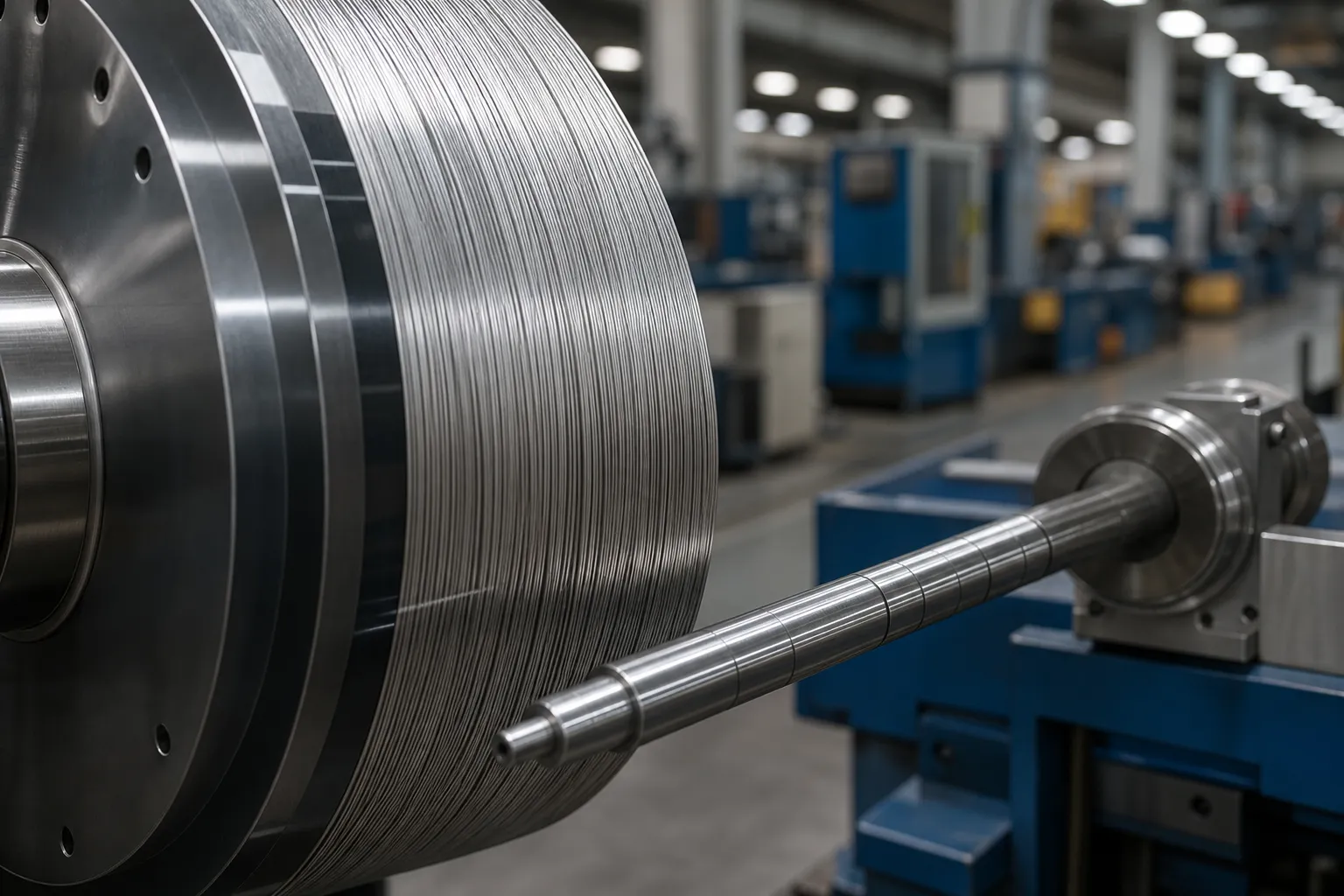
*Engineering concept illustration. It identifies a manufacturing-stage mandrel and measurement context; it is not a customer-site photograph or proof of a delivered machine.*
Keep Mandrels, Core Wire and Finished Medical Devices Separate
The search term *medical mandrel straightening* often brings together different workpieces and different responsibilities. A reusable mandrel, a coil-fed core wire, a needle tube and a finished guidewire can each need different loading, contact, cleaning and quality controls. Treating them as one product can create an unsafe process claim.
| Item | Typical engineering question | Boundary to preserve |
|---|---|---|
| Discrete manufacturing mandrel | Is the bow or runout compatible with its next manufacturing operation? | Do not assume it is a finished implant or a clinical device. |
| Coil-fed medical wire | Can the line control cast, helix, cut length and coating condition? | This is a continuous-feed process, not necessarily a discrete mandrel process. |
| Needle tube or stylet | Which lumen, tip, wall or surface features must not be contacted? | Tube geometry and cleanliness requirements need their own validation. |
| Finished guidewire or catheter component | Is any correction permitted after final processing? | Product, regulatory and clinical claims are outside a generic equipment article. |
For related but distinct production routes, see medical wire straightening, needle tube and stylet straightening, and the medical component solutions hub.
Define the Manufacturing Stage Before Choosing a Method
Distortion may be introduced by drawing, centerless grinding, heat treatment, coating, transfer, reuse or handling. The same visual bend can require a different response before and after a coating step. A part still scheduled for later grinding can have a different contact strategy from a finished or coated mandrel with a cosmetic or functional surface requirement.
Freeze the following inputs before a sample trial:
- controlled drawing revision, material specification and manufacturing stage;
- nominal and actual diameter, length, end form and any local changes in stiffness;
- whether the part is bare, coated, ground, heat treated, cleaned or previously used;
- incoming bow, runout or other geometry distribution from representative parts;
- the feature, datum and support condition used by the customer's reference inspection;
- surfaces that may be supported, driven or corrected, and protected zones that may not be contacted;
- released-part acceptance definition, including repeat measurement and handling condition.
An equipment quotation should not convert a competitor's diameter range or automation description into a StraighteningTech specification. MSI, Chamfr and other specialist pages establish that dedicated mandrel equipment exists in the market; they do not establish the range, force, coating compatibility or quality-system scope of a different supplier.
Select a Datum That Represents the Required Function
The reading from a probe is only useful when the reference is defined. A low-force probe can still produce misleading results if the part is seated inconsistently, a coated zone changes contact, or an end feature is used without confirming that it represents the required axis.
Candidate datum strategies may include approved end features, a defined straight reference section, or a mathematical axis generated from specified measurement stations. The final choice must be correlated with the customer's reference gauge. If the customer accepts a free-state straightness value while the machine measures a supported rotating signal, the relationship between those two methods needs to be demonstrated rather than assumed.

*Engineering concept illustration. It shows why contact and coating protection require workpiece-specific validation; it does not specify a universal mandrel fixture or allowable contact force.*
Measure With Enough Resolution, but Also Enough Context
A single midpoint reading may hide local bends, end effects or setup errors. A useful sample-test plan defines the measurement stations, support positions, rotation or translation path where applicable, sensor contact conditions and method for separating part geometry from fixture signal.
For each measurement method, document:
| Measurement control | Why it matters |
|---|---|
| Datum realization and seating check | Prevents a dirty, worn or poorly supported feature from appearing as a bend. |
| Probe contact or optical setup | Contact force, surface reflectivity and coating condition can affect the signal. |
| Axial stations and orientation | A local defect can be missed when only one span or direction is checked. |
| Released measurement condition | A clamped or tensioned reading is not automatically the final free-state result. |
| Gauge correlation | Connects equipment readings to the customer's controlled acceptance method. |
The correct question is not simply whether measurement is contact or non-contact. It is whether the method is repeatable for this material, surface, geometry and acceptance characteristic. The broader selection principles are explained in contact versus non-contact straightness measurement.
Correct Incrementally and Protect the Surface
Any candidate correction method must be selected from the part's permitted contact zones, stiffness distribution and deformation map. It may involve controlled local correction, guided multi-point contact, or another workpiece-specific route. The process cannot be specified safely from a product name alone.
Before force or displacement is applied, the engineering review should define support locations, correction locations, contact materials, indexing or orientation controls, maximum permitted correction attempts and the stop conditions for a part that no longer responds predictably. Coatings, polished surfaces, small end features and local diameter changes may require dedicated tooling or may rule out a proposed contact route altogether.
The correction loop should be closed:
- identify the controlled part family and recipe;
- inspect and reject damaged, contaminated or out-of-scope parts;
- load the approved datum and confirm seating;
- measure the initial geometry map;
- select the approved support and correction plan;
- apply an incremental correction within the agreed limit;
- fully release force and restraint;
- remeasure the required stations and route the part to OK, NOK or engineering review.
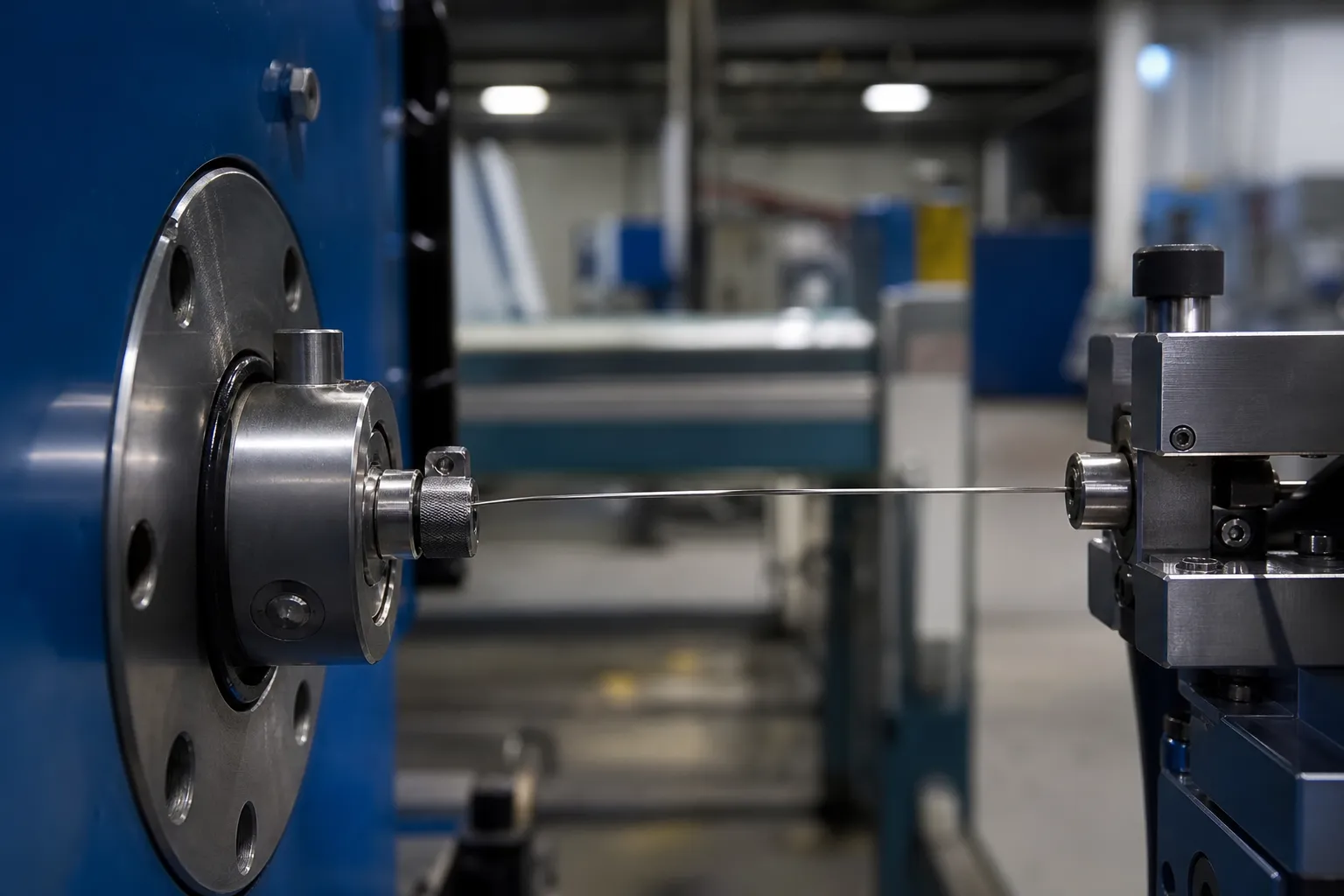
*Engineering concept illustration. It emphasizes released-state inspection and traceable review; it is not evidence of a customer acceptance result.*
Released-State Verification Is the Acceptance Gate
A temporary reading under pressure, clamping or tension is not a released-part acceptance result. After correction, the mandrel must be released and measured under the agreed condition. The trial record should retain the incoming reading, datum method, correction sequence, final reading, inspection method and disposition. Where surface, coating, cleanliness or material integrity is relevant, those checks must be identified as separate acceptance items rather than silently folded into “straightness.”
| Acceptance item | Example evidence required |
|---|---|
| Geometry before and after | Raw readings tied to the agreed datum and station map |
| Repeatability | Reseat and repeat readings, plus customer-gauge correlation where required |
| Surface protection | Controlled inspection method and approved visual criteria |
| Process response | Defined maximum attempts and engineering-review route for no-progress parts |
| Traceability | Part/lot identity, recipe version, operator or automation event and result record |
Information Needed for a Medical Mandrel Straightening Review
Next steps for a medical mandrel project: confirm the machine concept with the shaft, tube and profile straightener selection guide, then frame the business case with the cost structure of a straightening machine.
Send the controlled drawing, material and manufacturing stage, representative bent and normal samples, coating or surface requirements, allowable contact zones, incoming geometry data, customer inspection method and released-part acceptance limit. Also identify any cleanliness, validation, documentation or regulatory responsibilities that apply to the production step.
StraighteningTech can then review the workpiece family, possible datum, protected zones, candidate measurement and correction route, and the evidence required for a sample-test plan. A final machine configuration is proposed only after those inputs and validation criteria are agreed.
FAQ
Can a coated mandrel be straightened?
Only after the coating, contact zones, allowable marking criteria and released-part inspection method are reviewed. A coating does not automatically make correction impossible, but it changes the validation burden.
Is a mandrel the same as medical wire?
Not necessarily. A discrete mandrel and a coil-fed wire can have different functions, loading methods, geometry controls and cleanliness requirements. They should not share a process plan without a workpiece review.
Can a machine reading replace the customer gauge?
No. The two methods may be related, but that relationship needs a documented correlation and repeatability review.
Can a straightness value be guaranteed before a sample test?
No. Final accuracy, cycle time, contact method and automation level depend on the drawing, material state, protected features, samples and agreed acceptance method.