
A rotating indicator trace can contain several effects at once. It may reflect the workpiece axis, local roundness, cylindrical form, a datum relationship, support seating, fixture error, probe setup or an interrupted feature. Calling every high reading a “bend” can lead to the wrong correction action and can damage a part that actually needs a measurement or machining review.
This guide explains how to diagnose the signal before a straightening decision. It does not establish a StraighteningTech measurement system, tolerance, sensor resolution, datum procedure or correction capability. The controlled drawing and customer inspection method are required for final decisions.

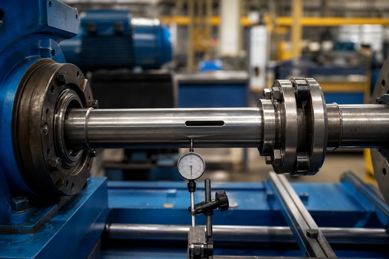
*Engineering concept illustration. It shows that a rotating signal can include form variation; it is not a measurement result for a customer part or a prescribed inspection setup.*
Name the Characteristic Before Reading the Gauge
Roundness describes a cross-sectional form condition. Axis bend describes the spatial path of a reference axis. Runout is a rotating measurement relative to a datum setup and can include multiple contributors. Coaxiality, concentricity and cylindricity also have distinct definitions and inspection requirements. The drawing must identify which characteristic controls acceptance.
| Signal or characteristic | Diagnostic question |
|---|---|
| Roundness / lobing | Does the local radius change as the section rotates? |
| Axis bend | Does the reference axis change position along the length? |
| Runout | Which datum, supports and probe station create the reading? |
| Coaxial relationship | Are multiple features being compared to a defined common axis? |
| Fixture signal | Does reseating or changing support orientation change the result? |
See shaft straightness, runout and TIR and coaxiality versus runout for related terminology.
What a Rotating Trace Is Made Of
A probe reading taken while a part rotates is, mathematically, a mix of components that repeat once, twice, three times and more per revolution. Reading the mix is the core diagnostic skill. A once-per-rev component means the surface is, on average, further from the rotation axis on one side than the other — which is the signature of either an axis offset between the part’s reference geometry and the rotation axis, or of a bent axis displacing the section as a whole. A twice- or three-times-per-rev component means the section is oval or lobed: the local radius itself changes around the circumference, a form condition of the cross-section that no amount of axis correction removes. Higher-frequency content usually reflects surface texture, keyways and interrupted features, or vibration entering through the supports.
The decisive separation between the two once-per-rev causes is axial. A true bend displaces different stations by different amounts and often in different directions, so the once-per-rev component’s amplitude and phase change as the probe moves along the part. A pure eccentricity condition — centers offset, seat offset, chuck runout — produces a once-per-rev component that keeps the same phase and proportional amplitude at every station. One trace at one station cannot distinguish them; a short axial map routinely can. That is the reasoning behind the multi-station discipline above, and behind multipoint measurement arrangements that read several stations in one setup.
Where Lobing Comes From
Lobing is rarely random — it carries the fingerprint of the machining that produced the surface, which is what makes it diagnostic. Three-lobe out-of-roundness is the classic signature of parts ground on centerless machines, where the part floats between wheel, regulating wheel and blade and the geometry locks into a three-point stability condition. Even-lobe ovality traces back to opposing clamping or distortion relieved after machining — a thin sleeve released from a chuck, a part that relaxed after heat treatment. Odd lobing beyond three appears with certain workholding arrangements and with relapsing of interrupted cuts. Knowing the part’s process route therefore tells you what lobing to expect and whether an observed lobe count is a workpiece reality or an artifact of the current setup: a lobe count that changes when the part is reseated in different orientations is being generated by the setup, not the part.
Inspect the Datum and Setup First
Before interpreting the part, verify the center features, journals or other reference surfaces, support condition, cleanliness, probe contact, rotation method and axial station. A damaged center, burr, dirty seat, incorrect support or probe contact on an interrupted surface can create an apparent runout that does not represent axis bend.

*Engineering concept illustration. It illustrates feature-aware journal measurement; actual datums, probe tracks and angular masks depend on the controlled workpiece.*
Use a reseat/repeat check and compare multiple stations. If the trace changes substantially after setup is repeated, investigate fixture or datum realization before applying correction force.
Compare Multiple Stations and Orientations
Axis bend usually requires an axial map. Local roundness or lobing may appear at one station but not another. A single total indicator reading at one point cannot prove which contributor dominates. Record station locations, orientation, reference condition and the trace or calculated result required by the acceptance procedure.
*Engineering concept illustration. It represents a multi-feature rotational measurement question, not an approved fixture or a conclusion that the observed signal is bend.*
Separating Spindle Error From Part Error
On any rotating instrument, the reading contains the part’s geometry plus the rotation error of the instrument itself — spindle runout, bearing wander, support eccentricity. Precision metrology has standard separation techniques for this, and their logic is worth knowing even when the full apparatus is not available. Reversal methods measure the part in one orientation, then rotate the part exactly half a revolution relative to the fixture and measure again: part error keeps its sign in part coordinates while setup error keeps its sign in machine coordinates, so combining the two traces separates them. Multistep methods extend the same idea through a series of indexed orientations. On a production straightening machine, the practical descendants are simpler: reseating the part in a different clocking orientation and checking whether the trace rotates with the part or stays fixed in the machine tells most of the story, and comparing readings before and after swapping a support identifies which element contributes what.
These checks cost minutes and prevent the most expensive mistake on this page: correcting a bend that lives in the bench. They also make the eventual correlation to the customer gauge meaningful, because both sides of that comparison are then measuring parts rather than setups — the premise underlying gage R&R studies on straightening lines.
A Practical Diagnostic Sequence
The checks above assemble into a fixed order of operations that experienced lines follow before any correction decision. First, clean and inspect the seating features — centers, journals, support vee blocks — for damage, burrs and debris, since the cheapest explanation is always the setup. Second, take a trace, reseat the part in the same orientation, and retrace: disagreement beyond the setup’s established repeatability stops the investigation at the fixture. Third, reseat in a rotated orientation: a trace that follows the part is a part signal; one that stays fixed in the machine is a machine or fixture signal. Fourth, map at least three stations along the length and note how the once-per-rev component’s amplitude and phase behave: varying amplitude and rotating phase indicate bend; constant phase with proportional amplitude indicates eccentricity. Fifth, look at the lobe content in relation to the part’s machining history before believing any form conclusion. Only then choose the response — correction for confirmed axis bend within approved zones, or the alternative routes for everything else, with the released-state condition treated per loaded versus released measurement.
The sequence exists because each step filters a class of false positives that would otherwise survive to the next. Skipping ahead to correction is how parts get pressed for eccentricity fixtures, ovality and chucking artifacts — damage that no later measurement undoes.
Select the Response From the Diagnosis
If the evidence supports an axis-bend condition and there are approved contact/support zones, a candidate straightening route may be evaluated through a sample test. If the signal is mainly roundness, interrupted geometry, a datum issue, fixture error or a separate feature relationship, a different process or inspection review may be required. Do not use straightening to compensate for a measurement problem.
For controlled local correction, see point-press straightening. For correlation to the final inspection method, see machine gauge versus customer gauge correlation.
Validate With the Customer Gauge
The sample plan should include known/reference conditions where available, repeat setup, multiple stations, released-state measurement, part and fixture identification, raw data retention and customer-gauge correlation. The result should state which characteristic was evaluated and which uncertainty or setup limitations remain.
FAQ
Does high TIR always mean the shaft is bent?
No. TIR can include datum, roundness, fixture and other contributors. Diagnose the setup and multiple stations first.
Can straightening correct roundness?
Not as a general conclusion. Roundness is a different geometric condition and may require a different process or inspection route.
Why repeat the setup?
Rereading after reseating helps distinguish a workpiece signal from support, datum or fixture variation.
What does a three-lobed trace usually indicate?
Most often, a surface produced by centerless grinding, where the three-point contact of wheel, regulating wheel and blade locks the section into a three-lobe form condition. It is a cross-sectional form issue, not an axis issue, and it should be verified against the part’s machining history before any response is chosen.
How can I tell eccentricity from bend with one probe?
Move the probe along the part and watch the once-per-rev component. Bend shows varying amplitude and shifting phase between stations; eccentricity keeps the same phase and proportional amplitude everywhere. If the probe cannot move, mapping several stations with a moved setup achieves the same separation at the cost of reseating discipline.
Does reseating the part in a different orientation really separate machine error?
Yes, in its simplest form. Part error rotates with the part; machine and fixture error stay fixed in machine coordinates. Comparing traces at two clockings shows which class dominates the reading. Formal reversal and multistep methods refine the same principle when numbers, not just classification, are required.