
Multiple displacement readings can turn a long-shaft inspection from a single peak into an error map. That value depends on more than the sensor: support geometry, datum seating, probe contact, rotation/indexing, synchronization, environmental conditions and the calculation rule all affect what is being reported.

*Engineering concept illustration. It is not a sensor specification, installed system or verified measurement result.*
Define the Characteristic Before Selecting Sensors
First state whether the acceptance characteristic is centerline straightness, local bow, runout relative to a datum, profile deviation or another controlled result. A sensor voltage or displacement trace is not itself the customer requirement. The inspection plan must identify datum features, supports, stations, orientations, span, calculation, units, limits and the state in which the part is accepted.
| Element | Question to close |
|---|---|
| Datum | Which features establish the reference axis or surface? |
| Support | Does it replicate the customer or released-part condition? |
| Probe path | Are contact points functional surfaces and protected from damage? |
| Stations | Do they capture known bend zones and feature transitions? |
| Rotation/indexing | How is orientation preserved between readings? |
| Calculation | How are readings converted into the controlled characteristic? |
For datum controls, see shaft center-hole cleaning and datum preparation and fixture repeatability and datum seating.
How an LVDT Works, and Why Its Physics Matters
The linear variable differential transformer earns its place on production machinery through a short list of physical virtues. Inside the housing, a primary coil is excited with an alternating current, and two secondary coils sit either side of it; a ferromagnetic core, attached to the probe tip by a slim push rod, slides along the axis. With the core centered, the induced voltages in the two secondaries balance; displace the core and the balance tips in proportion to the movement. The electronics read the amplitude and phase of that imbalance and report displacement. Because the core never touches the coils, there is no friction or wear inside the sensor; because the coupling is inductive, the reading is largely indifferent to dust, oil mist and humidity that blind optical sensors; and because the moving mass is small, the tip can follow moderate surface motion faithfully. The trade-offs are equally physical: it needs signal conditioning and calibration against a reference, the raw output is relative rather than absolute, and the probe tip itself is a mechanical component with its own condition, force and wear story.
Where Errors Enter Between Probe and Number
Treating the chain as one system, as the section above demands, means knowing the specific doors through which error walks in. Thermal drift: the sensor body, the fixture and the part all expand and contract with temperature, and on a machine that warms through a shift, a morning zero and an afternoon reading are not the same event — hence reference checks on a master at intervals the procedure defines. Mounting: a probe on a long, unsupported bracket is a cantilever with its own compliance, and vibration or cable pull moves the whole assembly relative to the part, indistinguishable from part movement in the data. Dynamics: when the part or probe moves during scanning, the stylus mass and tip force set a speed limit beyond which the tip skips or lags, writing false features into the trace. Contact condition: tip wear flattens the intended radius and changes where the reading sits on a curved surface. None of these is exotic; each is controlled by written procedure — zero method, master check interval, scan speed, tip inspection — which is precisely what the validation framework above asks the system description to contain.
Treat the Measurement Chain as One System
An LVDT may be suitable for relative displacement, but the measured result also includes sensor mounting, fixture deflection, signal conditioning, timing, part seating and operator or automation behavior. Record every element in the chain so a later shift in the result can be investigated.
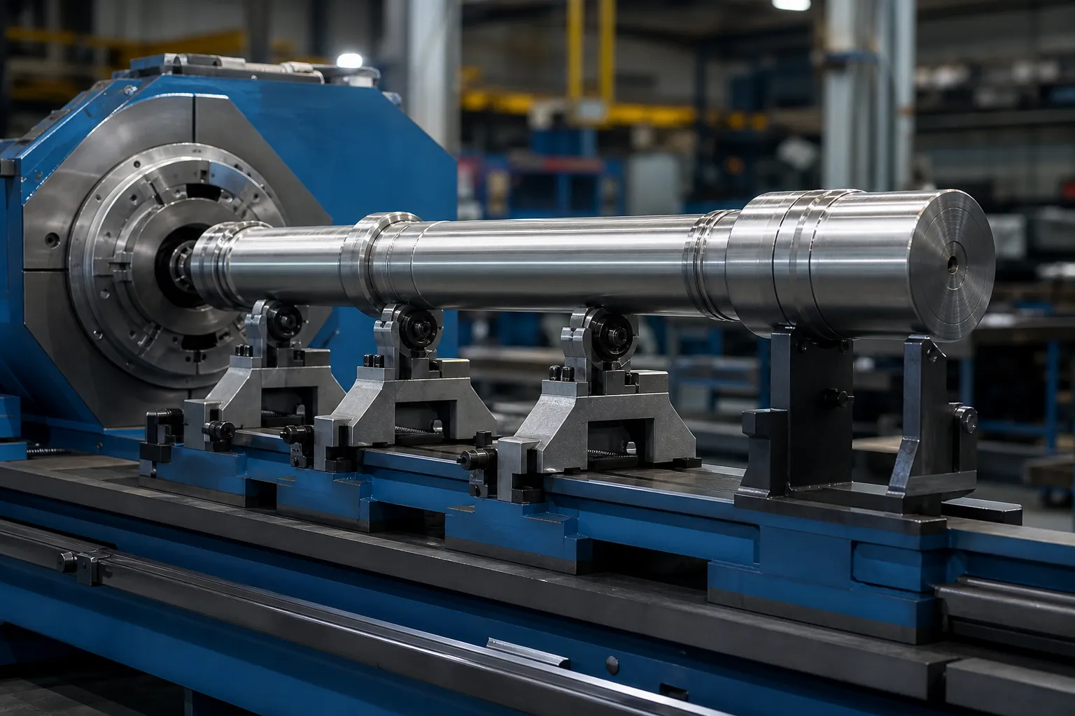
*Engineering concept illustration. Fixture stiffness, sensor position and guarding require project-specific engineering.*
The controlled procedure should cover sensor identification, reference/master check, mounting condition, cable protection, zero method, sample orientation, support cleanliness, data acquisition settings and data retention. A repeated reading from an unstable fixture is not evidence of repeatability.
Synchronize Location, Orientation and Readings
Multipoint data is useful only when each value can be assigned to a known position and condition. If the part rotates or moves, define the encoder/index, station coordinate, direction of travel, dwell or sampling condition, and what happens if a signal is missing. The result should preserve the raw or traceable source data needed to reconstruct the map.
Avoid interpreting a localized peak without checking seating and contact. Reseat tests, reversed orientation where appropriate and repeated baseline reads can distinguish a part feature from a false indication.
Choosing Station Count and Placement
How many stations, and where, is a geometry question before it is a budget question. The error modes of slender parts are smooth in space: a bend is a low-frequency curve, so a modest number of stations — placed where the physics says the information lives — reconstructs it well, while doubling the count in uninformative positions buys data volume, not accuracy. Informative positions are predictable: mid-span between supports where a bow reaches its excursion; each stiffness transition on stepped parts, where peaks like to hide; immediately beside functional features whose relationship to the datum matters; and the free ends, which anchor the map. The failure mode of sparse placement is aliasing in its practical form — a short kink sitting between two stations contributes to neither reading cleanly, and a correction aimed at the reconstructed map presses in the wrong place. The honest way to close this risk is not infinite density but a validation: map a set of parts at high density once, confirm that the production station set reconstructs the same peaks and amplitudes, and document that comparison as the station-plan justification.
Turning the Map Into a Correction Decision
The map exists to drive action, and its action vocabulary has three entries: where to press, in which direction, and how hard to expect the part to respond. Peak position and direction come from comparing stations around the maximum; on a part rotating between stations, preserving angular indexing — the synchronization discipline above — is what converts separate readings into a vector, not a pile of magnitudes. Expected response comes from the stiffness story the map already tells: a peak on a heavy section needs a different correction plan than the same amplitude on a thin one, and peaks at stiffness transitions deserve the respect described for separating bend from roundness and setup effects before any press follows. What the map must not do is trigger correction on unverified signals: a localized reading that has not survived a reseat check is a hypothesis, not a peak. That guard rail — map, verify, then correct, with released-state measurement closing the loop — is the same sequence that makes automatic shaft straightening converge in few strokes instead of many.
Correlate to Released-Part Acceptance
Measurement during clamping or correction may be useful for process control, but it does not automatically prove the released shaft meets the requirement. Compare the line method with an approved released-part method on representative samples across normal variation. See loaded versus released straightness measurement for the boundary.
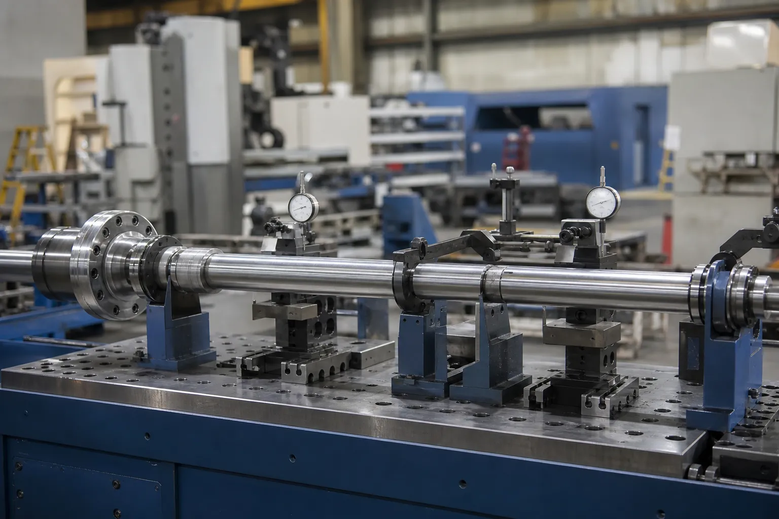
*Engineering concept illustration. The reference method, supports and acceptance calculation must be controlled by the approved quality plan.*
A correlation plan should define matched samples, blind comparison where practical, datum/support equivalence, calibration status, bias review, repeatability/reproducibility review, allowed difference, escalation and change-control rules. Refer to machine gauge versus customer gauge correlation and gage R&R for straightening lines.
Inputs Needed for a Measurement Study
Provide the drawing and characteristic definition, existing inspection method, part geometry and datum features, material/manufacturing stage, expected bend locations, sample population, environmental constraints, desired data record and customer acceptance method. Use the straightening sample test and acceptance guide to establish the trial record, then contact StraighteningTech for an application discussion.
Required Validation Before a System Claim
Any multi-point measurement claim needs a defined probe and datum setup, calibrated references, repeated or reseated readings on representative parts, and customer-gauge correlation. A generic machine capability is not a verified result.
FAQ
Does adding more measurement stations automatically improve accuracy?
No. Stations placed where the geometry has information — mid-span peaks, stiffness transitions, functional features, ends — improve the map. Stations added elsewhere add data volume and cost while leaving reconstruction essentially unchanged. Validate the chosen set once against a dense map and document the comparison.
Why do LVDT readings drift over a production shift?
Most often thermal: sensor, fixture and part expand at different rates as the cell warms, shifting the zero. Mechanical causes come next — bracket compliance, cable pull, tip wear. The control is procedural: a defined zero method and reference-master checks at set intervals, with any shift beyond the procedure’s limit triggering investigation rather than quiet re-zeroing.
Can multipoint LVDT data replace final inspection?
Only through correlation. In-process multipoint data drives the correction loop; the acceptance decision belongs to the released-state method the customer recognizes. When the two have a documented correlation on representative parts, the line method gains standing — until then it is process control, not release.
Related StraighteningTech Resources
See how automatic shaft straightening works, straightening sample test and acceptance and shaft straightness vs runout vs TIR for generic control boundaries that apply before any capability claim on LVDT Multipoint Shaft Measurement.