
A spline shaft transmits torque through the flanks of its teeth, not through its outer surface alone. The spline section, the ground bearing journals between splines, the seal diameters, shoulders and threaded ends each carry a geometric relationship to one rotation axis, and the fit of the mating sleeve or hub depends on that relationship holding true along the whole length. Straightening a splined shaft therefore means controlling the axis without ever touching the flank geometry that makes the part valuable.
A workable spline shaft straightening solution answers four questions before any press moves: which diameter represents the functional axis at each station, whether the spline’s own teeth may be used as a measurement reference, where correction force may legally act, and how the corrected part will be accepted — including the fit check with the mating component, not just an indicator reading.

Why Spline Shafts Break the Default Straightening Recipe
| Spline Shaft Feature | Straightening Risk | Project Response |
|---|---|---|
| Spline teeth | Press or support contact can brinell, bend or mark flanks; damaged flanks destroy the fit and the torque capacity | No-contact rule: correction force and supports only on smooth diameters adjacent to the spline |
| Interrupted spline surface | A sensor riding on tooth tips reads tooth form and pitch error, not the axis | Measure on journals or the minor diameter, or use a gauge sleeve/master to convert teeth to a continuous reference |
| Torque-twist history | Overload can twist the shaft; lead and index error remain after any bend correction | Measure spline lead/index separately; declare twist out of press-straightening scope |
| Long slender body | Long length-to-diameter ratio means self-weight sag and easy overcorrection | Validate support spacing, use fine force increments and re-measure after each pass |
| Heat treatment distortion | Induction or through hardening leaves a multi-point bend map, often with reversals | Multi-station measurement and sequenced correction, not a single mid-span press |
| Seal and shoulder features | Local loading near a shoulder concentrates stress and can mark a seal diameter | Padded or radius-matched tooling, press points kept clear of transition zones |
Define Which Spline Shaft Is in Scope
| Spline Shaft Family | Typical Context | Engineering Route |
|---|---|---|
| Transmission / gearbox output shaft | Volume production after heat treatment, before spline finish | Automated multi-point measurement and press correction on journal zones |
| PTO and agricultural driveline shaft | Long standardized profiles, repair-heavy market | Long-span machine or targeted manual process; fit check with mating yoke |
| Motor shaft with pinion or coupling spline | Electric motor and pump assemblies | Journal-based straightening consistent with rotor and bearing datums |
| Aerospace and actuator splined shaft | Fatigue-critical, tight lead and index tolerances | Full metrology, restricted deflection, documented process validation |
| Worn or damaged repair shaft | Fretting, bruised flanks, corrosion, hammer marks | Inspect and disposition first; straightening cannot restore tooth geometry |
Neighboring applications should not be folded into this page. Long hollow drivelines with welded yokes are a tube-straightening and balancing problem covered in our drive shaft straightening solution, and hardened gearbox shafts whose spline is only one feature among gears and journals follow the route described in the gearbox shaft straightening solution. The present article stays with shafts whose spline is the defining feature.
Build the Measurement on a Defensible Reference
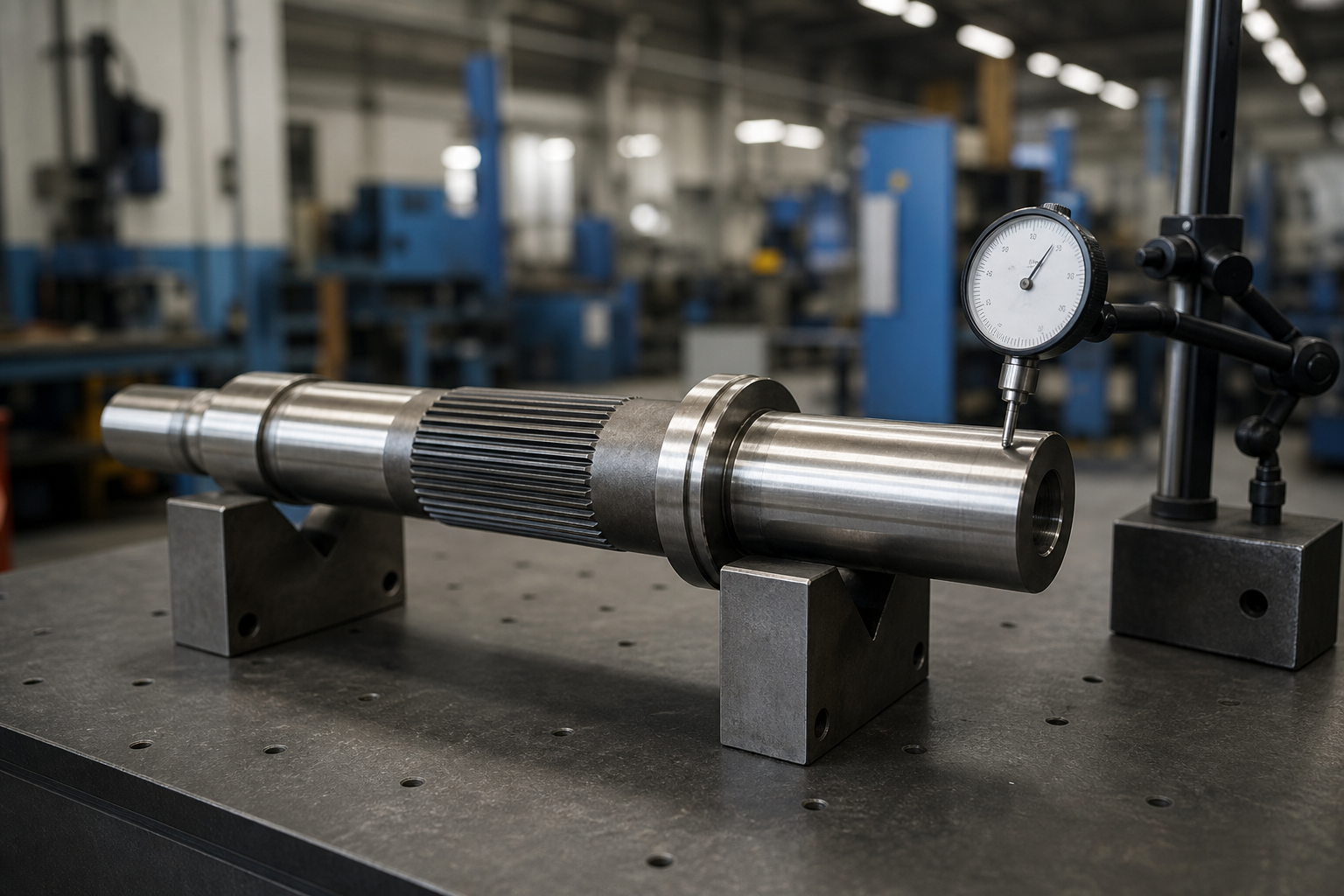
The most common error in splined-shaft measurement is reading a dial indicator directly on tooth tips and calling the result runout. The tooth circle is an interrupted, form-carrying surface; its reading mixes pitch error, lead error, tooth damage and true axis position into one meaningless number. A defensible measurement chain uses one of three references:
- Ground journals and centers: where the drawing defines the axis from bearing journals or center holes, measure there, and verify the spline relationship only where the drawing requires it.
- Minor diameter or dedicated gauge diameter: the root circle between teeth is continuous on many splines and can carry a vee support or a narrow sensor tip; qualify it first, because root fillets can be rolled or malformed.
- A master sleeve or spline gauge: slip a precision sleeve over the spline and measure on its ground outside diameter. This converts teeth into a continuous surface, and the fit behavior of the sleeve itself becomes a live functional check. Production spline straighteners use exactly this principle — a master device per groove or spline section to resolve the pitch diameter for accurate correction.
Support condition matters as much as sensor choice. A long splined shaft sagging between distant vee blocks reports a bend that changes with every support move. Freeze support positions, correlate them with the customer’s gauge, and remember that straightness, runout and TIR answer different questions — the distinctions are set out in our article on shaft straightness vs runout vs TIR.
Separate the Three Conditions That Look Like One Bend
| Condition | How It Shows | Correct Response |
|---|---|---|
| Global bend of the axis | Runout readings rise and fall consistently along the shaft in one plane | Press straightening at mapped points on smooth sections |
| Torque twist | Journal runout acceptable; spline lead, index or roll error out of tolerance; hub fits tight on one end | Not correctable by pressing; disposition by re-machining where stock allows, or reject |
| Local flank or form damage | Readings jump when the sensor crosses one tooth zone; sleeve fit is local, not uniform | Inspect the flanks; replace, re-cut or blend per drawing — do not bend the shaft to hide it |
Twist deserves emphasis because it arrives from exactly the loading a spline is designed for. A torque overload past yield rotates one end of the spline relative to the other; from the outside the shaft still looks straight. Straightening will pass it on the runout report and the assembly will still bind or wear. If your parts see overload events, lead and index checks belong in the same inspection cycle as runout.

Press Points and Supports: The No-Contact Rule
Correction force on spline flanks is a scrap event. Even a soft press can flatten a crest or shift metal on a flank, and the resulting clearance or interference shows up months later as fretting, wear or a hub that will not assemble. The contact map for a splined shaft is therefore strict:
- Press and support only on smooth ground or turned diameters adjacent to the spline, sized so the contact patch stays off shoulders and seal edges.
- When the spline run is so long that no smooth zone sits near the correction point, use conforming inserted tooling that bridges the tooth roots without loading flanks — and validate it on sacrificial parts before production.
- Place supports symmetric around the measured high point so the bending moment is designed, not accidental; keep spans short enough that the correction is local.
- Protect threaded ends, cross-drillings and keyways with the same discipline described for hardened shafts in our guide to straightening after heat treatment.
Control Springback on a Slender Section
Long splined shafts are compliant, so the axis moves under small forces and springs back almost as far. The correction cycle that survives production treats every press as an experiment with feedback:
- Measure the full bend map in one setup.
- Correct the largest deviation first, at the mapped high point, over-traveling by the predicted springback.
- Re-measure before the next press; slender shafts couple strongly, and a correction at one station shifts readings at both neighbors.
- Work down the remaining points in descending order, re-verifying earlier stations after each pass.
- Accept only when every station and the functional fit check pass in the same clamping.
The over-travel prediction, the coupling behavior and the classic failure signatures of under- and over-correction are treated in our article on shaft straightening springback compensation. Automated cells run this loop closed; our overview of how automatic shaft straightening works shows the machine architecture behind it.

Know Why the Shaft Bent in the First Place
Straightening returns geometry; it does not remove the cause. Spline shafts arrive at the press for a short list of repeatable reasons, and each one changes what a correction is worth:
| Root Cause | Typical Evidence | Implication for Straightening |
|---|---|---|
| Heat treatment distortion | Multi-point bend after induction or through hardening; repeatability across a batch | Core production case; correct in the window before finish machining |
| Machining stress relief | Progressive bow after heavy turning or milling of one side | Correct, then verify stability after a stress-relief interval or next operation |
| Handling and impact damage | Local kink, hammer or drop marks near one station | Sharp local bends concentrate strain; assess radius of curvature before pressing |
| Operating overload | Twist with or without bend; witness marks on hub flanks | Geometry correction cannot restore yield strength after a torsional event |
| Misalignment in service | Flank wear concentrated on one side, fretting corrosion at the hub interface | Wear surfaces mean the shaft is a wear part, not a straightening candidate |
Failure-prevention practice in the spline industry consistently puts misalignment, overload and handling damage at the top of the cause list — which is precisely why a straightening proposal should ask for the failure history and the upstream process before quoting a correction cycle. A shaft that bends the same way in every batch is a process problem with a straightening fix; a shaft that arrives twisted, fretted or impact-kinked is a disposition problem wearing a straightening costume.
Sample Testing Before Production Release
Because flank damage is irreversible, a splined-shaft process is validated on samples, never on the first production batch. A minimal qualification set includes:
- At least five representative parts measured before and after correction, at every drawing station, in the frozen support condition.
- A fit check with the production go gauge or a master sleeve on every sample, before and after the final press pass.
- Flank inspection — visual or optical — to prove the no-contact rule held under real tooling positions.
- Recorded springback values per press point, which seed the compensation model for production.
- An acceptance record signed against the drawing tolerances, including lead and index where specified.
Acceptance Must Include the Fit, Not Only the Dial
| Acceptance Element | What to Specify |
|---|---|
| Runout / TIR at defined stations | Per station, in a stated support condition, referenced to journals or a qualified master sleeve |
| Spline functional fit | Go / no-go gauge, master sleeve torque check, or specified flank clearance after correction |
| Lead, index and roll | Checked where the drawing requires; twist is a separate characteristic from bend |
| Flank condition | No brinelling, crest flattening, flank pickup or new marks from tooling |
| Surface integrity after hardening | Crack inspection where the part is hardened and fatigue-critical |
| Remaining machining stock | Verification that correction left allowance for any final grind or spline finish |
Frequently Asked Questions
Can you press directly on the spline?
No. Direct press contact on teeth risks flank and crest damage that straightening cannot repair. Correction force belongs on smooth diameters adjacent to the spline, or through validated bridging tooling that loads only the root diameter.
How do you measure runout on a splined section?
Use the journals where the drawing allows, the minor diameter where it is continuous and qualified, or a precision master sleeve slipped over the teeth so the sensor reads a ground continuous surface. Reading an indicator on tooth tips mixes tooth geometry with axis error and gives a false bend map.
My splined shaft is straight but the hub binds. Why?
The likely causes are twist, flank damage, or lead/index error — all invisible to a journal runout check. Measure spline lead and index, inspect flanks for bruising or fretting, and test the fit with a go gauge or master sleeve before and after any correction.
Is a spline shaft measured and straightened like a motor shaft?
The machine loop is the same measure–press–re-measure sequence used for the automatic motor shaft straightening solution, but the reference and the contact rules differ: the spline adds an interrupted surface for measurement, protected zones for tooling, and a functional fit check that a plain shaft never needs.
How much bend can be corrected on a splined shaft?
The workable range depends on length-to-diameter ratio, material condition and where the smooth correction zones sit relative to the deviation. Slender shafts tolerate large angular corrections in principle but couple strongly between stations; hardened short shafts tolerate little deflection per pass. The number that matters is set per part family during sample testing, not read from a generic table.
Build the Solution from the Fit, Not the Dial
A spline shaft is accepted when the mating hub or sleeve assembles and transmits torque as designed. Straightening serves that outcome: measure from journals or a qualified master, keep every press and support off the flanks, treat twist as a separate and non-pressable characteristic, and close the loop with a functional fit check. Freeze those four decisions, and the correction itself becomes routine engineering.
To turn this spline shaft guidance into a purchase decision, start with the straightener selection walkthrough and pressure-test the numbers with the budget picture for a straightening machine.