
Automatic straightening can generate process signals that merit investigation: an unexpected force-displacement response, an acoustic event, an abnormal geometry change, a repeated correction failure or another defined condition. Those signals can help a production line stop, isolate and route a part for review. They are not automatically proof that a crack exists, and they are not automatically a substitute for a qualified NDT method.
This article is a risk-control framework. It does not claim that StraighteningTech currently supplies crack-detection sensors, detects a defined crack size, meets a particular standard or replaces magnetic-particle, ultrasonic, eddy-current or other formal inspection. Those capabilities require a separately verified method, known samples and quality-system approval.

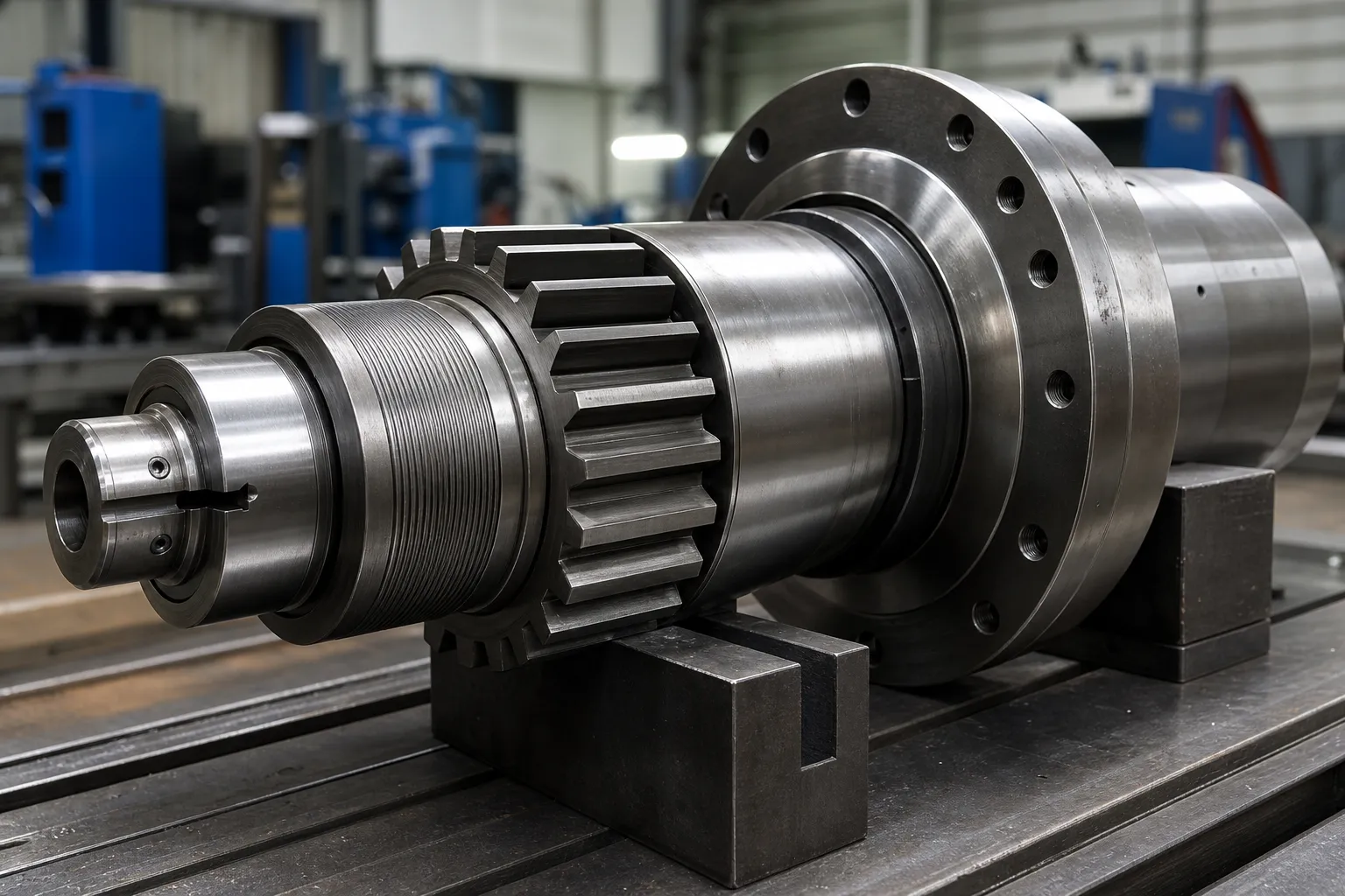
*Engineering concept illustration. It shows a candidate measurement-and-correction context; it does not indicate that a crack sensor or detection algorithm is installed.*
The development plan should use known normal, known suspect and, where permitted, known-reference conditions to establish whether the signal correlates with the required decision. It must not infer detection performance from a competitor feature list or a single successful trial.
Why Straightening Is a Natural Integrity Checkpoint
Cracks relevant to straightening have a short list of origins: prior manufacturing wrote them in, or the correction process itself put them there. On the incoming side, quench cracks from heat treatment, seams and folds from rolling or drawing, and grinding abuse on machined surfaces all exist before the part reaches the press — and a part carrying a sharp discontinuity responds differently to plastic bending than a sound one, because the discontinuity concentrates strain locally. On the process side, aggressive correction, repeated reverse bending, and correcting a material in a brittle condition can initiate cracks that no incoming inspection would have found. The two categories demand different responses: incoming cracks are a supplier-quality problem surfaced at your station, while process-initiated cracks are a process-design problem owned inside the correction loop — the boundary worked through in over-straightening and cracking.
Either way, the straightening station sees the part in a state no inspection bench replicates: under load, in plastic deformation, with its stiffness and response visible stroke by stroke. That is why the press is a natural integrity checkpoint even though it is not an NDT instrument. The signals are there for the taking; the engineering work is making them mean something.
The Signal Families Available at the Press
Four signal families are realistically available on straightening equipment, and each has a distinct information content. Force–displacement behavior is the richest: a sound section deforms along a repeatable curve, and departures from the qualified curve shape — an early load drop, an unexpected plateau, a step in the response — indicate that the section is behaving abnormally somewhere along the load path, whether from a material discontinuity, a setup fault or a geometry outside the expected map. Acoustic events are the sharpest: a distinct release of strain energy is audible and can be sensed, though ambient noise on a production floor makes standalone acoustic detection fragile. Geometry response covers cases where the part moves less, more, or differently than the qualified correction model predicts — a crack crossing the correction zone reduces local stiffness and shows up as anomalous movement. Convergence failure — repeated correction attempts that never reach the target — is the slowest but most insidious signal, because its common causes are mundane, and the rare cause is a part that cannot be straightened because it is no longer continuous in the way the process assumes.
None of these families is specific to cracking. Each one answers “is this part behaving like the qualified population?”, not “does this part contain a crack of a given size?”. That gap between anomaly detection and flaw detection is the honest boundary of process monitoring, and it is exactly why the verification route — not the alarm itself — carries the quality decision. The force–stroke interpretation background sits alongside point-press process practice, where the same curves are used for correction control.
Integrate Risk Controls Into the Correction Loop
A controlled route can be:
- identify part/lot, drawing revision and approved recipe;
- complete incoming inspection and hard-reject checks;
- establish the datum and acquire baseline geometry/process data;
- perform the approved correction sequence;
- evaluate the defined process signals and geometry response;
- release and remeasure the part;
- route PASS, rework-eligible, hold-for-verification and reject outcomes separately;
- retain traceability, evidence and reviewer disposition.
The route should include a no-progress condition. Repeated correction attempts without the expected response may be a reason to stop and isolate the part, not a reason to keep applying force.
Define NOK Isolation and Verification
NOK is not one universal category. The line should distinguish a measurement/setup issue, a process-monitor alert, a confirmed nonconformance, a rework candidate and a part that requires independent inspection or engineering disposition. Physical segregation, status labeling, traceability and authority to release must be defined.
*Engineering concept illustration. It represents process-routing decisions, not an installed crack-detection or automatic sorting system.*
| Event | Minimum response to define |
|---|---|
| Process signal exceeds threshold | Stop/hold rule, data capture and responsible review |
| Geometry does not respond as expected | No-progress limit and engineering evaluation |
| Formal inspection required | Approved method, acceptance criterion and authority |
| Rework considered | Maximum attempts, remeasurement and separate quality approval |
| Confirmed reject | Isolation, traceability and disposition record |
For the broader line controls, see NOK sorting and rework limits and straightening sample test and acceptance.
Where measurement response is part of the investigation, machine gauge versus customer gauge correlation helps define the boundary between a line signal and the controlled customer acceptance method.
Thresholds, False Alarms and Missed Events
Any threshold drawn on a process signal trades two failure rates against each other. Set it tight, and normal part-to-part variation — different lots, temperature drift, tooling wear, honest measurement scatter — crosses it regularly, flooding the review route with good parts until operators learn to ignore alarms. Set it loose, and the abnormal parts that motivated the monitoring slip through unflagged. There is no datasheet value that resolves this trade; it is settled empirically by running the signal on a known-normal population to learn its spread, and where permitted, on known-suspect or seeded-reference parts to learn what the abnormal signature actually looks like. Only that pair of distributions justifies a threshold, and the honest summary of what was learned belongs in the validation record — including the false-alarm and missed-event behavior observed, not only the detections celebrated.
Two further rules keep thresholds honest over time. First, drift monitoring: as tooling wears and material lots change, the normal population moves, so the threshold must be reviewed on a schedule, not set once. Second, change control: a new part revision, a different material family, or a reworked die changes the qualified population, and the threshold work starts over. These are the same habits that keep measurement systems credible, applied to process signals.
Where Formal NDT Fits After an Alert
When the review route decides a part needs a definitive answer, the method must match the question and the geometry. Magnetic-particle inspection suits ferrous parts and surface-breaking discontinuities, and it is fast enough for segregation decisions in moderate volumes. Penetrant testing suits non-ferrous surfaces where coating and cleanliness permit it. Eddy-current methods respond to near-surface condition and can run in-line, with sensitivity that depends strongly on coil geometry versus part geometry. Ultrasonic methods reach internal volumes along bar and shaft axes, at the cost of coupling, calibration blocks and operator discipline. Selecting among them is a quality-engineering decision driven by the flaw orientation expected, the material, the surface state after straightening contact — witness marks and surface protection practices intersect here — and the acceptance authority. What the straightening station controls is not the NDT verdict but the integrity of the chain before it: the part is identified, isolated, protected from further correction attempts, and accompanied by its process data so the inspector knows why it was pulled.
Validate Before a Capability Claim
A responsible validation package identifies the workpiece family, material/process condition, sensing/monitoring method, sample population, known-condition references, thresholds, expected variation, false-alarm and missed-event assessment, verification route, data retention and quality approval. It also states what the system cannot prove.
No process-signal page should claim that it finds all cracks, replaces NDT or guarantees material integrity without an approved, workpiece-specific evidence package.
FAQ
Does a process alarm prove there is a crack?
No. It indicates a condition requiring the defined review route. The cause must be evaluated with the approved method.
Can automatic straightening replace NDT?
No. Straightening process monitoring and formal NDT have different purposes, methods and acceptance responsibilities.
Can a part be reworked indefinitely after an alert?
No. The process requires a maximum correction-attempt limit and a defined engineering/quality disposition route.
Which signal family catches cracks best?
None of them catches cracks in the NDT sense. Force–displacement behavior, acoustic events, geometry response and convergence failure all flag parts that behave unlike the qualified population. A part flagged by any of them goes to the verification route; a part that passes all of them is not certified crack-free — it simply behaved normally. That asymmetry is the design premise of every process-monitoring scheme on straightening lines.
How are thresholds set without a standard to cite?
Empirically, on populations. Run the chosen signal across a known-normal production sample to characterize its spread, and where reference conditions are available, across known-suspect parts to characterize the abnormal signature. The threshold is then drawn against both distributions, documented with observed false-alarm and missed-event behavior, and reviewed on a schedule as tooling, lots and seasons change.
What happens to a part after an alert is cleared?
Whatever the written route says, and only that: return to the normal flow with the event recorded, proceed to rework under the attempt limit, or pass to formal inspection with disposition authority named in advance. The failure mode to design against is the quiet return of alerted parts to the good bin by operator judgment, which is why physical segregation and labeling carry as much weight as the signal itself.

*Engineering concept illustration.*
Force鈥揇isplacement Curves in Straightening
A dedicated page for straightening force displacement curve guide is not maintained without validated query demand. Force鈥搒troke interpretation, safe limits and process stop conditions are explained in the point-press, multi-point and crack-detection pages. Any curve-based alarm must be validated on representative parts rather than copied from another material family.
Crack detection is strongest when the process prevents cracks in the first place – see over-straightening and cracking for the causes, and the manual vs automatic comparison for why automated correction limits reduce the risk.