
Elevator guide rail straightening is a manufacturing-stage geometry process. It is different from aligning installed rails in a hoistway. A production route must control the rail section, reference faces, length, bow, lateral sweep, twist, surface condition and the interfaces to machining, inspection and packing.
This guide is a workpiece-based engineering framework. It does not claim that StraighteningTech currently handles a particular rail profile, length, production rate or acceptance tolerance. Those points require a drawing review, representative rails, measurement agreement and a validated sample process.
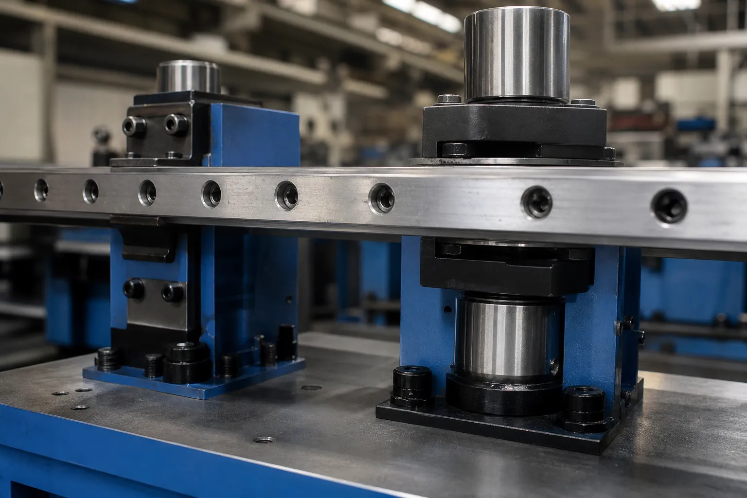
*Engineering concept illustration. It depicts a candidate manufacturing-stage rail process, not an installed-elevator alignment service or a delivered-machine record.*
Separate Manufacturing Straightness From Installation Alignment
Search results for elevator guide rail machines include dedicated straighteners, guide-rail production lines and installation questions. The manufacturing question is whether the delivered rail meets the controlled geometric requirement after all correction forces are removed. Installation alignment concerns the building, brackets, joints and field survey. They need separate measurement systems and should not be combined in one acceptance statement.
| Scope | Typical controlled issue | Do not substitute |
|---|---|---|
| Rail manufacturing | Section geometry, longitudinal bow, lateral sweep, twist and surface condition | A field plumb or rail-spacing check |
| Production-line integration | Feed, straightening, cutting, machining, inspection and packing interface | A promise that every line configuration is supplied |
| Hoistway installation | Brackets, joint alignment and verticality in the building | A factory straightening result |
The market structure supports this separation: Senbo presents dedicated guide-rail straightening equipment while Co-effort presents guide-rail production-line scope. A useful site architecture keeps the workpiece solution separate from an elevator guide rail production-line buying guide.
Related manufacturing geometry topics include linear guide rail straightening and railway rail straightening. They require their own section, datum and process review; neither is a substitute for an elevator rail qualification.
Define the Rail Section, Datum and Error Map
“Rail straightness” is incomplete until the section, reference faces, length span and measurement condition are stated. A T-shaped or other asymmetric profile can show vertical bow, lateral sweep and twist at the same time. A support pattern can also create apparent geometry if the rail sags under its own mass or rests inconsistently.
The engineering review should freeze:
- rail drawing, profile variant, length and manufacturing stage;
- datum faces, permitted support zones and cosmetic or functional protected zones;
- the acceptance characteristic for each plane and the method used to calculate it;
- whether twist is controlled, how orientation is indexed, and how intentional section variation is treated;
- incoming error distribution, handling condition and the reference gauge or inspection fixture;
- machining, cutting, joining, packing and downstream interfaces that can reintroduce distortion.

*Engineering concept illustration. It shows a possible full-length measurement approach; the actual sensor positions, span and datum must be validated for the rail family.*
Where Rail Distortion Comes From
A guide rail accumulates its geometry story long before it reaches a straightening station. Rolling leaves residual stress through the section, unevenly distributed between the head and the web of the profile; cooling on the mill bed adds its own field. Straightening performed at the mill counts as history — a rail that was rotary-straightened upstream arrives with its deformation budget partially spent and its response to further correction altered, the reverse-loading behavior covered for the Bauschinger effect. Cutting to length releases constraint at the ends, which is why end geometry often differs from mid-length behavior. Machining the guide faces removes surface material and lets buried stresses relax asymmetrically. And handling writes the final chapter: a long rail lifted at the wrong points, or stored standing under its own weight, collects bends that no upstream process intended. Each source predicts its own signature — where peaks sit, whether sweep or twist dominates — and reading that signature from the incoming map is what turns correction from generic pressing into a planned route.
The T-Section’s Mechanical Personality
An asymmetric rail section is not a round bar with corners. Its stiffness differs by direction — bending about one axis of the profile meets much more resistance than about the other — so vertical bow and lateral sweep are not two readings of one problem but two different mechanical responses, each with its own correction economics. The open profile is also torsion-sensitive: modest twist about the longitudinal axis displaces the guide faces at the ends in opposite directions, which is why a rail can measure acceptably for bow at every station and still present a twisted functional surface to the car shoes. And the guide faces themselves are the functional product: they are where contact is both mechanically necessary for measurement reference and cosmetically or functionally restricted, the tension that makes surface-protection tooling practice and conservative contact-zone choice — as the section above demands — inseparable from the geometry plan. The same asymmetry-first logic governs the structural profiles discussed for I-beam and H-beam straightening.
Measure Bow, Sweep and Twist as Different Signals
A rail can look straight in one view yet fail in another. The process should map the agreed stations and directions before correction. Vertical bow, lateral sweep and twist should be stored as distinct characteristics, not combined into a generic “bend” value.
| Characteristic | Measurement question | Engineering consequence |
|---|---|---|
| Vertical bow | Which datum plane and span define the result? | Determines support and correction direction |
| Lateral sweep | Is the web or guide face referenced consistently? | May need a different correction orientation |
| Twist | Which faces establish angular orientation? | Cannot be inferred from one linear probe |
| Fixture/sag signal | Does a reseat or changed support pattern alter the reading? | Requires setup review before correction |
Long-part support matters. A measurement map that changes when supports are moved is not yet a reliable correction map. The guide should therefore distinguish free-state behavior from the controlled support condition used by the drawing and customer inspection.
Choose Contact and Correction Zones Conservatively
Candidate correction can involve controlled point pressing, roll straightening or another section-specific method. The choice depends on the rail geometry, material condition, error pattern, accessible contact areas and surface-risk review. A point-correction sequence for a round shaft cannot simply be copied to an asymmetric rail.
Before a trial, define the approved supports, reaction path, load points, protective contact materials, orientation controls and maximum correction attempts. Do not apply force on a surface merely because it is accessible. Machined guide faces, reference faces, connection features and cosmetic zones may require protection or may be prohibited as contact points.
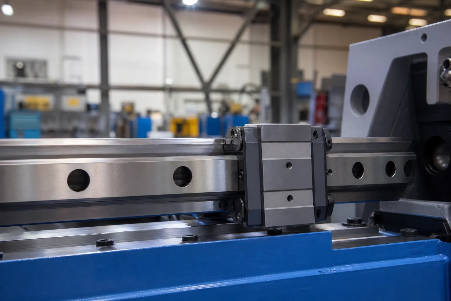
*Engineering concept illustration. It distinguishes a possible angular-correction problem from ordinary vertical pressing; it does not prove that a specific rail or machine supports torsion correction.*
Use a Measure–Correct–Release–Remeasure Loop
The final acceptance decision must be based on the released rail. A temporary reading while the rail is held by tooling or under correction force does not prove final geometry.
- identify the rail family, drawing revision and manufacturing stage;
- inspect for damage, wrong profile, unapproved surface condition or out-of-scope deformation;
- load the part in the approved orientation and verify support seating;
- capture the vertical, lateral and angular error map required by the acceptance plan;
- select the permitted correction plan and protect all no-contact zones;
- apply incremental correction within the approved limit;
- release force and restraint completely;
- remeasure, record disposition and route no-progress rails to engineering review.
Build the Sample Test Around the Customer Gauge
The sample plan should compare the machine method with the customer's controlled reference method. It should include typical and worst-case incoming rails, repeat setup checks, released-state readings, surface inspection, traceability and a defined route for rails that need repeated correction or fail to respond.
| Acceptance item | Evidence needed before a production claim |
|---|---|
| Bow, sweep and twist | Raw before/after readings tied to drawing datums and spans |
| Fixture repeatability | Reseat study and support-condition record |
| Surface protection | Approved inspection criteria and photos or reports |
| Handling and line interface | Qualified transfer, orientation and safety review |
| Throughput and automation | Timed, validated run for the agreed rail family |
Information Needed for an Elevator Guide Rail Straightening Review
Provide the controlled rail drawing and section variants, length, material and manufacturing stage, incoming geometry data, datum and acceptance method, permitted support and contact zones, surface requirements, production target, handling constraints and representative rails. StraighteningTech can then review candidate measurement, support and correction architecture and define the sample-test evidence needed before a machine configuration is proposed.
FAQ
Is this an elevator installation-alignment guide?
No. This page covers factory manufacturing geometry. Hoistway alignment, brackets and field installation require a separate scope.
Can one correction station control bow and twist?
Not automatically. Bow, lateral sweep and twist require separately defined datums, measurement tracks and correction validation.
Can a rail be accepted while it is clamped?
No. Acceptance must follow the agreed released-state condition. Clamping can mask springback or sag.
Can a section, length or cycle time be specified from this article?
No. Those values require a verified rail family, machine capability, tooling review and representative sample test.
Why does the same rail profile distort differently across lots?
Because mill rolling conditions, cooling bed position, upstream straightening history and storage all vary lot to lot, and each writes a different residual-stress pattern into the section. The practical response is per-lot incoming mapping rather than a single inherited correction recipe.
Is point pressing or roll straightening better for guide rails?
Neither is a default. Point pressing suits discrete, mapped peaks on an asymmetric section with defined contact zones; roll methods suit continuous correction of compatible sections at volume. The boundary between the routes — and the sample-test evidence each demands — follows the press versus roller straightening comparison, applied with the rail’s protected faces in view.
How does twist show up when only linear probes are used?
As opposing displacement of the same face at opposite ends — a reading pattern that looks like contradictory bows from a single probe track. Confirming twist needs orientation-aware measurement on defined faces at multiple stations, which is why the error map stores bow, sweep and twist as separate characteristics rather than one combined value.
Moving from manual elevator guide rail correction toward automation? The straightener selection guide for shafts, tubes and profiles and the straightening machine FAT checklist are the natural next steps.