
A connecting rod converts rotating motion into reciprocating motion under load, in tension, compression and bending, millions of times per operating hour. Unlike a shaft it has no single rotation axis to true up. Its geometry lives in the relationship between two bores — the big end on the crankpin and the small end on the wrist pin — and straightening means restoring that relationship: bore-to-bore parallelism, twist, center distance and bore geometry, in the assembled and torqued condition the rod runs in.
This article is about straightening the connecting rod body itself. Two related resources on this site cover a smaller workpiece family: the connecting rod sleeve straightener solution and the ZD90 connecting rod straightener machine straighten slender sleeve-type link rods and pins (ø1.5–8 mm diameter, 45–95 mm length) for power tools and assemblies — not the engine rod body. The engine rod body discussed here is corrected on dedicated rod alignment stands and presses in engine remanufacturing shops; the process and acceptance logic below documents that practice.
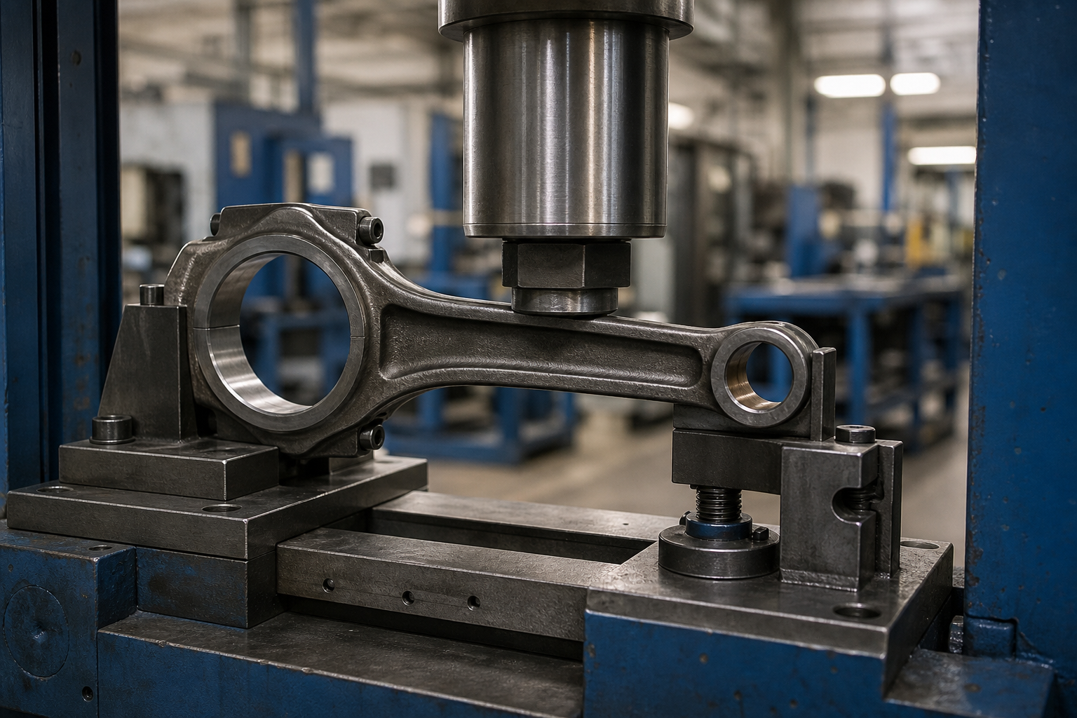
What “Bent” Means on a Connecting Rod
| Deformation Mode | What Changes | Correction Route |
|---|---|---|
| Beam bend | The shank bows between the bores; the bores stay parallel but offset | Press correction on the I-beam shank between padded tooling |
| Beam twist | One bore rotates about the shank axis relative to the other | Torsional correction in a rod fixture with controlled end restraint |
| Bore parallelism error (bend in the bore frame) | The small-end axis tilts out of parallel with the big-end axis in the plane of the rod | Press correction at defined points; verify on the alignment fixture |
| Big-end distortion | Ovality or taper in the big-end bore, often after bolt stretch or a rod-bolt failure event | Not a bending problem: cap-face machining and rebore/hone, the classic reconditioning route |
| Small-end distortion | Bore out-of-round or size loss | Bore and re-sleeve; see the sleeve straightener solution referenced above |
The first three rows are press-straightening work on the rod body. The last two belong to machining reconditioning. Shops that conflate them press a rod to force an indicator reading, distort the bores further, and lose the part — which is why the measurement step below separates bend and twist from bore geometry before anything is loaded.
Measure in the Assembled, Torqued Condition
A connecting rod is a two-piece part from the big end’s point of view. The cap, the parting faces, the bolts and their torque all participate in the bore’s final geometry, so every credible measurement follows the same discipline:
- Inspect for cracks first — magnetic particle inspection of the shank, parting faces and bolt lugs. Straightening a cracked rod converts a detectable defect into a future failure.
- Assemble the cap with new or known-good bolts, torqued to specification. An untorqued rod measures a bore that does not exist in service.
- Set the rod on an alignment fixture: the big end on a fixed arbor or between check plates, a pin or arbor through the small end.
- Read bend and twist with dial indicators at defined gage points — the classical rod aligner arrangement used in engine reconditioning for decades.
- Measure bore dimensions, center distance and cap face condition separately; do not let bore error masquerade as bend.

The fixture, not the eye, defines the truth. Workshops without a rod aligner try to infer bend from feeler readings against a surface plate, which mixes fixture error, plate error and bore error into one number. The professional standard — reflected in engine remanufacturing practice from specialist rod shops to production engine plants — is a dedicated alignment stand with both bores on gauge hardware.
Press Correction on the I-Beam
Beam bend and bore-parallelism error are corrected by pressing the shank between supports that grip defined zones of the rod:
- Support and press on the I-beam shank and the boss sections — never across a bore, a bolt lug, the parting face or a drilled oil passage.
- Place the press point at the measured high point of the deviation, with tooling radii matched to the beam section so contact stays off flange edges.
- Correct in small increments and re-check on the aligner after each press; a rod that measures clean after two light passes is a better part than one pressed once hard.
- Expect springback and set it deliberately: the same compensation logic used on shafts applies, and the rod’s short stiff beam makes overshoot easy.
- After the final press pass, re-verify bores, center distance and cap torque before releasing the part — pressing the beam shifts bore geometry a few tenths, and the reconditioning sequence must know the new baseline.

Fixture rigidity is half the process. Bench vices flex, and correction work done against a moving base produces unrepeatable results — an experienced machine shop principle that applies to rods as much as to any press work. Dedicated rod straighteners solve it with a stiff clamping frame and rod-specific tooling. The same discipline — rigid fixturing plus measured feedback — governs our production straighteners such as the ZD90 connecting rod straightener, which runs closed-loop automatic straightening (feed, measure, servo-correct, re-inspect) on small sleeve-type link rods.
Tooling marks are a quality defect in their own right. Rods are finished parts by the time they reach the press — machined bores, faced parting surfaces, sometimes shot-peened shanks — so anvils and supports need padded or radius-matched inserts, and any witness mark left on a bolt lug, oil hole or parting face is grounds for re-inspection of the affected feature before the rod moves on.
Straightening Sits Inside a Reconditioning Sequence
Engine remanufacturing practice runs connecting rod reconditioning as an ordered sequence, and straightening has a fixed place in it:
- Crack inspection and cleaning. Rods with indications leave the line here.
- Straightening. Beam bend and twist corrected on the aligner and press; re-checked in the fixture.
- Parting face machining. The cap and rod parting faces are surfaced true, closing the bore smaller.
- Bolt replacement and torque. New bolts to specification before any bore work.
- Bore restoration. Hone for small corrections or bore/turn for larger ones, finishing the big end to size, roundness and center distance.
- Final verification and weight management. Parallelism, twist, center distance, and weight matching within the engine set.
The order matters. Straightening before parting-face work means the bore operations finish a straight beam; straightening after boring would pull a finished bore out of position. And because face machining plus bore restoration remove material, center distance control is a reconditioning discipline, not a straightening one — the rod lathe and hone, not the press, hold it.

Know the Event That Bent the Rod
The correction decision starts with failure history, because the same indicator reading can mean very different things:
| Failure Event | Typical Geometry Signature | Disposition Logic |
|---|---|---|
| Hydrolock / debris ingestion | Sharp beam bend or small-end offset, often with piston damage in the set | Shock-loaded part; inspect for cracking, lean toward replacement |
| Over-rev / valve contact | Beam bend combined with twist; small-end distortion | Multiple modes loaded past yield; replacement unless damage is provably light |
| Bearing seizure / spin | Big-end discoloration and bore distortion, heat tint on the shank | Heat alters material response; full MPI and hardness check before any decision |
| Rod bolt stretch or improper torque | Big-end ovality with clean parting faces | Reconditioning route: faces, new bolts, bore and hone |
| Machining / handling distortion | Small consistent bow across a production or repair batch | The straightforward correction case; stable and repeatable |
Which Rods May Be Straightened at All
| Rod Type | Position on Straightening |
|---|---|
| Forged steel rod (automotive, diesel, agricultural) | The classic correction candidate; reconditioning sequences include straightening as standard |
| Powdered-metal / sintered rod | Generally replaced, not bent; cracking behavior of the material makes press correction a risk decision |
| Aluminum rod (some performance and small engines) | Material fatigue behavior argues for replacement; follow the engine manufacturer’s service position |
| Fracture-split (cracked) rod | Cap faces cannot be machined, so classical reconditioning is out; bore correction and any bending must follow the OEM disposition |
| Rod with bolt failure or seizure history | Crack-inspect and disposition before any correction; the load event that bent it may have done invisible damage |
This is also where honest engineering beats optimism: some forum threads ask whether a bent rod from a hydrolock or over-rev event should be straightened, and the working answer in professional engine building is that the severity of the event decides. Light, measurable bend in an otherwise sound forging is reconditioning territory; a rod that has been compressed, twisted or shock-loaded past yield is a replacement, whatever the indicator says after pressing.
Acceptance Criteria That Reflect the Running Engine
| Acceptance Element | What to Specify |
|---|---|
| Bore parallelism (bend) | Deviation limit over a stated gage length, measured on the aligner in the torqued condition |
| Twist | Angular deviation limit between bore axes, same setup |
| Bore size, roundness and taper | Per drawing after final hone/bore, not after pressing |
| Center distance | Minimum and maximum, controlled at the machining stage with rod set matching |
| Crack inspection | MPI before straightening and after final correction where specified |
| Weight and balance | Weight class within the engine set; bobweight influence documented where balancing follows |
| Bolt condition | New or qualified bolts, torque recorded, no re-use of stretched fasteners |
Frequently Asked Questions
Can a bent connecting rod be straightened safely?
A forged steel rod with a light, cleanly measured bend and a clean crack inspection is routinely straightened and reconditioned. Rods with severe bends, twist from overload, bolt failures, or made from powdered metal, aluminum or fracture-split forgings are replacement candidates. The event that caused the bend matters as much as the bend itself.
Why measure with the cap torqued?
Because the big-end bore only exists in its running geometry with cap, bolts and torque applied. Readings taken on a loose cap measure assembly clearance and bolt-hole slop as much as bend.
Does straightening affect the bores?
Yes, slightly, which is why straightening comes before bore restoration in the reconditioning sequence. Pressing the beam can shift bore geometry by small amounts; the parting-face and honing operations that follow restore size, roundness and center distance on the corrected beam.
How is rod twist corrected?
Twist is corrected torsionally: the rod is clamped at the big end in a rigid fixture, and controlled counter-rotation is applied about the beam axis at the small end, in increments, with a re-check on the aligner after each correction. Twist correction deserves extra caution because it works the beam in shear, and on a rod with any seizure or overload history it is usually a replacement situation rather than a correction.
Is rod straightening related to crankshaft straightening?
The parts meet in the engine, and both are fatigue-critical, but the metrology differs completely. A crankshaft is trued to its main-journal axis as described in our crankshaft straightening solution, while a connecting rod has no rotation axis at all — it is corrected to a bore-to-bore relationship on an alignment fixture.
Build the Solution Around the Two Bore Axes
A connecting rod straightening solution stands on four fixed decisions: crack inspection before loading, measurement in the torqued condition on a real alignment fixture, press correction restricted to the beam between padded, radius-matched tooling, and reconditioning sequence control so bores, faces and center distance are finished after the beam is true. With those in place, dedicated rod straightening equipment turns a labor-intensive repair judgment into a repeatable shop process — and tells you honestly when a rod should be replaced instead.
Whether you are upgrading an existing connecting rod line or buying new, the straightener selection walkthrough and the budget picture for a straightening machine frame the trade-offs before you talk to suppliers.