
A turbocharger shaft is the rotor at the heart of a turbocharger: a slender shaft that carries the turbine wheel at the hot end and the compressor wheel at the cold end, spinning on a small journal bearing or ball-bearing cartridge at speeds that reach several hundred thousand rpm. At those speeds the rotor’s geometry is not a comfort item — shaft straightness sets the running clearance of the bearing system, the seal behavior, the vibration signature and ultimately the survival of the wheels. A bowed turbo shaft that passes a static inspection can destroy itself in seconds at operating speed.
Turbocharger shaft straightening is therefore a high-stakes, micro-precision correction problem that sits closer to precision spindle work than to general shaft work. It is also a field full of bad advice: forum threads asking whether a bent turbo shaft can be straightened usually end with “replace the core”, which is the right answer for a mechanic with a hammer and a V-block, and the wrong generalization for a remanufacturing operation with a controlled process. A turbocharger shaft straightening solution must answer five questions:
- What exactly is the shaft — one-piece turbine-and-shaft rotor, or a shaft with wheels assembled by welding or brazing?
- Is the deviation a true centerline bow, thermal distortion, assembly-induced distortion, or damage (bent wheel, cracked shaft)?
- Which measurement convention and supports reproduce the functional axis — bearing journals, centros, or the wheel pilot datums?
- Which correction route is approved at which process stage — micro point-pressing, stress-relief treatment, ou sucata?
- How will post-correction verification, balancing and any cycle limits be enforced?
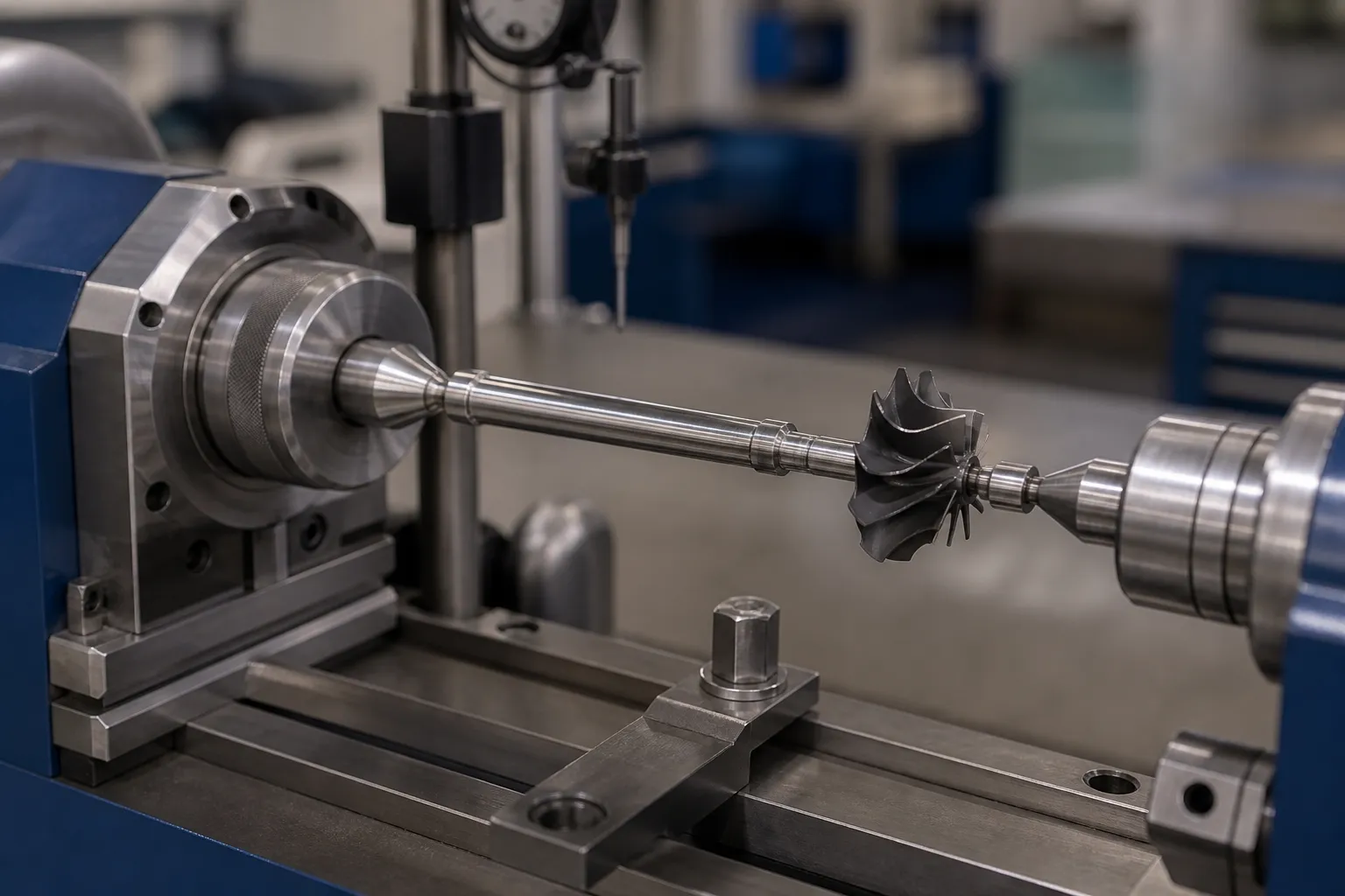
*Ilustração do conceito de engenharia: a turbocharger rotor supported and measured for a controlled correction study. Não é uma fotografia do site do cliente. Actual force limits, support zones and process approval require drawings and representative sample tests.*
Know the Rotor Architecture First
The correction strategy depends on how the rotor is built, and offering one process for all of them is a red flag in any supplier discussion:
| Rotor Type | Construção | Straightening Implication |
|---|---|---|
| One-piece turbine shaft | Turbine wheel and shaft machined from one casting/forging | Correction acts on the shaft section; wheel is the datum system |
| Welded / friction-welded rotor | Shaft welded to turbine wheel | Weld distortion is a primary bow source; heat-zone correction rules apply |
| Brazed or assembled compressor side | Compressor wheel mounted on shaft nose | Assemble-induced distortion; often correctable before wheel mounting only |
| Ball-bearing cartridge rotor | Shaft rides on preloaded cartridge | Tightest clearances; correction windows are narrowest |
How Turbo Shafts Deform
- Soldagem / joining distortion. Where the shaft is joined to the turbine wheel, the weld or braze zone introduces asymmetric residual stress and the rotor bows in a repeatable direction. This is a production-process deviation and the most systematically correctable class.
- Distorção do tratamento térmico. Hardening of the shaft journals releases machining stresses; the rules and risks of alisamento após tratamento térmico apply fully.
- Thermal bow in service. A hot shutdown with the rotor stationary can deform a shaft permanently. Remanufactured cores show this signature — a smooth bow with no mechanical damage.
- Impact and FOD damage. A compressor wheel that ingested debris, or a rotor dropped at disassembly, shows bent wheels, dented seal surfaces, sometimes cracked shafts. This class is an inspection-and-reject problem, and correction is not on the table until cracking is ruled out.

Medição: Reproduce the Functional Axis
The functional axis of a turbo rotor is defined by its bearing journals — the surfaces that actually run in the bearing system. Everything else (seal diameters, wheel pilot, nut thread) is measured relative to that axis. The measurement plan follows:
- Support on the bearing journal datums (or between centers where process centers exist and are proven concentric to the journals — the datum-selection logic in stepped shaft measuring datum selection applies).
- Map multiple stations: diários, seal diameters, shaft mid-span, wheel pilots and nose. A single mid-span reading cannot distinguish a bow from wheel runout. Multi-point electronic mapping per LVDT multi-point shaft measurement is the standard architecture.
- Separate error types: journal roundness versus axis bow is the classic confusion, covered in roundness versus bend in rotating measurement. Wheel face and pilot runout belong to the wheel, not the shaft axis; a rotor with a true shaft and a bent wheel does not go to the straightening press.
- Mind the measuring force. The shaft is thin; stylus force between supports bows it measurably. Non-contact sensors or the loaded-versus-released conventions in medição de retilinidade carregada versus liberada resolve this.
New Production versus Remanufacturing
Turbo shaft correction splits into two worlds that share metrology but not risk:
New Production
In rotor manufacturing, the deviation is process-generated — weld shrinkage, tratamento térmico, machining stress — and the population statistics are stable. Correction recipes are validated per rotor type, the correction station sits at a defined point between operations, and every rotor continues to balancing and final inspection. Here straightening is a routine, audited production step, and its economic value is the recovery of expensive rotor forgings and machined assemblies.
Remanufacturing and Repair
A returned core arrives with an unknown history: overspeed, superaquecimento, oil starvation, foreign object damage, previous disassembly attempts. The same visible bow can come from a benign thermal soak-back or from a rotor near its fatigue limit. This is why remanufacturing correction is gated by inspection, not measurement alone:
- crack detection on the shaft and wheel before any correction;
- bearing journal condition — scoring, overheating discoloration, size — evaluated for regrind potential;
- wheel integrity — bent, eroded or cracked wheels disqualify the rotor regardless of shaft geometry;
- prior-correction history where known, counted against a hard cycle limit;
- a defined escape route: rotors failing any gate go to teardown and parts recovery, not to the press.
O que “Precisão” Means Here
Turbo rotor runout specifications are among the tightest in general metalworking. Journal-to-journal runout and shaft runout relative to the bearing axis are commonly specified in single-digit micrometers, with seal-diameter runout tighter still because seal clearance governs oil control. Three implications for the solution:
- The measurement system is the process bottleneck. Supporting a thin rotor, rotating it true, and resolving 1 μm runout repeatably is harder than applying a 3 μm correction stroke. Budget and engineering go to metrology first.
- Correction strokes are microscopic. The press operates in a regime where frame compliance, drive resolution and thermal drift are the dominant error sources — the same regime discussed for precision rotors in machine tool spindle straightening.
- Documentation is part of the deliverable. Incoming map, correction record (posição, AVC, cycle count), outgoing map, balance record — serialized per rotor. For remanufactured cores this record chain is frequently a customer or certification requirement, not an internal courtesy.
Correction Routes

Micro Point-Pressing
The applicable route for a true centerline bow is the processo de endireitamento por pressão de precisão scaled to its smallest and most careful form: soft or non-marring supports positioned per the bend map, a displacement-controlled micro-stroke at the apex — typically a few micrometers of stroke — and immediate re-measurement. Because the shaft is thin and hard, springback dominates; the process needs validated compensação de retorno elástico rules per material state, and pressing is never applied at or near the weld zone, seal lands, or thread without explicit process approval.
Thermal Stress Relief
Where the bow stems from residual stress (soldagem, tratamento térmico), a controlled stress-relief treatment can relax the bow without mechanical contact. It is slower and less precise than pressing, and the two are sometimes sequenced — relieve first, then micro-press the remainder — because pressing a highly stressed part invites drift later.
Not Correctable
Cracked shafts (crack inspection is a gate before any correction), bent or eroded wheels, damaged bearing journals needing regrind, and rotors whose remaining grinding stock cannot clean up after correction. For these the route is the remanufacturing decision tree, não a imprensa. Repeated correction cycles on the same rotor must be limited and recorded — the reasoning in Limites de classificação e retrabalho NOK applies, with the added weight that this is a rotor.
Verification and Balancing: The Non-Negotiable Pair

Correction of a rotor is only half the job. Acceptance requires:
- Post-correction runout map in the identical support and measurement condition as the incoming map, at all functional stations.
- Form verification: redondeza do diário, surface finish and seal-surface condition untouched by tooling; any witness mark on a bearing or seal surface is a reject.
- Rebalancing. Straightening redistributes mass geometry; every corrected rotor goes back through the balancing machine, and the balance record belongs with the correction record. This is the same coupling of straightness and balance that governs crankshaft work.
- Gauge capability per medidor R&R para endireitar linhas — at turbo tolerances the measurement system is the process.
Machine Architecture for Micro-Correction Work
The machine that corrects turbo rotors looks almost passive next to a production shaft straightener, because its defining components are metrology and control, not force. The press frame is small but extremely stiff, so the stroke that reaches the rotor is the stroke the control commanded. The ram drive resolves sub-micrometer steps and holds position against load without overshoot. Supports are bespoke per rotor family — shaped to the bearing journal or designated loading zones, made of softer or protected materials, and never touching seal lands or threads. The measuring head is integrated into the same setup, so the rotor is mapped, corrected, and re-mapped without re-chucking, because re-clamping a thin rotor between a press cycle and a measurement cycle introduces more error than the correction itself removes. Operators matter as much as hardware: loading a rotor into the fixture, interpreting the bend map, and deciding press-again-or-release is a skilled task, and the best cells formalize that decision logic into the machine control so the skill lives in the process rather than in one person. Buyers should evaluate a turbo shaft straightening offer by asking to see the measurement data flow first and the press second — the order of priority tells you whether the supplier understands the workpiece.
Common Failure Modes
- Correcting past a crack. A slightly bent rotor from a seized or overheated turbo may be cracked. Pressing it “back to zero” without inspection creates a fragility bomb. Crack detection precedes correction, always.
- Chasing wheel runout as shaft bend. The map shows runout at the wheel pilot; the press is applied to the shaft; both ends are now worse.
- Pressing on forbidden zones. A stroke applied at a seal land, journal or thread fixes the map and destroys the rotor functionally.
- Straightened but never rebalanced. The rotor passes static runout and fails at speed — vibration, seal rub, wheel contact. Balance verification is part of straightening acceptance, not a separate optional step.
- Forum-grade advice in a production setting. “Tap it back with a hammer” destroys rotors; “replace the core” wastes recoverable production rotors. The correct professional answer is a controlled correction process with inspection gates.
Leitura relacionada: machine tool spindle straightening e electric motor rotor straightening for the neighboring rotor families, plus como funciona o endireitamento automático do eixo for machine-level context. For a turbocharger shaft feasibility study, prepare the rotor drawing, the runout specification at each functional station, and incoming runout maps plus crack-inspection records from a representative rotor sample.