
A front-wheel-drive half shaft looks like a finished assembly, but its straightening problem lives in the individual components long before the boots and joints are fitted. The shaft barrel that carries an outboard Rzeppa fixed joint and an inboard tripod plunge joint must be straight in itself, and the stub or spider that forms the tripod side must keep its three trunnions on a common, correctly phased geometry. A bend introduced by heat treatment, soldagem, machining or handling does not only create runout. It changes the operating angle of both joints, accelerates roller and race wear, and shows up in the vehicle as shudder, vibration and premature boot failure.
A CV joint and tripod shaft straightening solution therefore cannot be specified from shaft length and diameter alone. It has to define which component is on the machine, which functional features define the reference axis, where the part may be supported and loaded without marking raceways or splines, and how the corrected part will be verified against the customer’s own gauge and assembly acceptance method.

Esta é uma ilustração de conceito de engenharia, não é uma fotografia do site do cliente. Actual support tooling, probe stations and correction capacity depend on the joint family, the material condition and sample tests on representative parts.
Why CV and Tripod Shafts Need a Dedicated Straightening Solution
The half-shaft family combines several features that a general-purpose shaft press does not have to deal with. Each of them changes either the measurement or the correction step.
| Workpiece Feature | Endireitando o risco | Resposta do Projeto |
|---|---|---|
| Induction-hardened zones on raceways and trunnion seats | Local over-pressing can crack or craze the hardened layer | Restrict correction points to zones defined on the drawing as non-functional |
| Thin-wall shaft barrel, sometimes swaged or rolled | Point loading can dent or ovalize the tube | Use conforming supports and limit deflection per stroke |
| Splines at both ends | Unsupported spline loading damages flanks and minor diameters | Locate from spline pitch circle with dedicated masters, never from tooth tips |
| Welded joint attachments | Weld shrinkage moves the axis between datum features | Measure before and after the welding stage that creates the distortion |
| Stub shaft with three tripod trunnions | The three-lobed geometry makes runout readings ambiguous | Define the trunnion-based datum scheme and the measurement plane explicitly |
| Assembled joints with grease | Roller stack clearance masquerades as shaft bend | Straighten the bare shaft or stub, not the greased assembly |
| Final dynamic balance requirement | Geometric runout and mass unbalance are different defects | Keep straightening and balancing as separate, sequenced controls |
Define Which Workpiece Is Actually in Scope
“CV joint straightening” is used loosely for at least four different workpieces. A proposal should replace the generic name with the exact part family, because the datum scheme and the machine concept diverge immediately.
| Parte Família | Geometria Típica | Principal questão de alisamento |
|---|---|---|
| Bare half-shaft barrel before joint assembly | Tube or solid bar with splined or welded ends | Centerline bend between end datums; ovality kept separate from bend |
| Stub shaft or spider for a tripod plunge joint | Three trunnions at 120 degrees on a spherical or cylindrical hub | Trunnion-to-axis relationship and hub runout after heat treatment |
| Tripod housing (outer pot with three tracks) | Hardened pot with internal raceways | Usually not a straightening part; track form and pitch dominate |
| Complete assembled half shaft | Barrel with both joints, boots and grease | Only limited verification is meaningful; correction must go back to the component |
Most industrial straightening projects on this family concern the first two rows: the bare barrel and the tripod stub. The paragraphs below treat both, and the same discipline applies to related shaft-type parts already covered in our solução de endireitamento do eixo de transmissão e automotive axle shaft straightening solution pages.
Modos de Deformação: Read the Part Before Touching It
Distortion in this family rarely arrives as a single clean bow. The measurement routine should be able to separate at least five modes, because each one has a different correction response.
- Simple bow of the barrel. One plane, one curvature, usually from heat treatment or material stress release. This is the mode that point-press straightening handles most predictably.
- S-bend or multi-lobe curvature. Two or more curvature reversals along the length, typical after welding at both ends or after aggressive turning. It demands multi-point correction in a defined sequence, not one big stroke.
- End-face or flange squareness error. The barrel is straight but the welded flange or joint seat is tilted. Pressing the barrel will not fix it; the tilt must be corrected at its own location or the part returned to machining.
- Trunnion geometry error on the tripod stub. Individual trunnion bend, trunnion-to-hub axis error, or 120-degree spacing drift after hardening. This is a small, duro, three-lobed part where probing strategy matters more than press force.
- Torção. Angular offset between the end splines. Straightening machines do not remove twist; it must be detected so that twisted parts are sorted out rather than “corrected” into scrap.

A useful first project step is a deformation census on a statistically meaningful batch: measure every part at fixed stations, plot the curvature shapes and classify them. The census tells you how many correction points the machine actually needs and whether a two-point press is being asked to do a multi-point job.
Measurement Datum: The Decision That Controls Everything Else
Every runout number is only as good as the axis it is measured against. For CV and tripod shafts the functional axis is defined by the features that locate the part in the vehicle: the bearing seats or ground bearing diameters on the barrel, and the trunnion seats or hub sphere on the tripod stub. Two datum strategies are common:
Rotation between centers or master vee-blocks on functional diameters. The part rotates, probes read total indicator reading at defined stations, and the curvature is reconstructed from multiple stations. This mirrors how the part behaves in the assembly and is the usual acceptance basis. The subtlety, covered in detail in our article on medição de retilinidade carregada versus liberada, is that clamping force and self-weight change the reading on slim barrels; the machine and the customer gauge must agree on support positions and clamping state.
Multi-point static probing of the free part. The part lies on defined supports without axial clamping and a set of probes records its shape. This avoids center-hole errors, which matter here because center holes at the spline ends are often machining conveniences rather than functional features.
For the tripod stub specifically, the datum question is sharper. Measuring runout of the hub against the trunnions, or trunnion runout against the hub axis, gives different numbers with different correction consequences. The drawing must be read to determine which relationship is the controlled characteristic, and the measurement plan must state it explicitly before any press cycle is programmed.
Processo de alisamento: Suporta, Protected Zones and Stroke Strategy
With the datum fixed, the correction step follows four rules.
Support and load only where the drawing permits. Raceway surfaces, trunnion seats, spline flanks and seal lands are protected zones. Supports should be conforming blocks on non-functional diameters, and the press ram should contact the part through a pad wide enough to avoid creating a local dent on thin-wall tubes. On hardened zones the allowable correction should be reviewed with the heat-treatment data, não assumido.
Correct in small, measured strokes. The machine measures, computes the curvature and the correction vector, presses, releases and remeasures. Springback is compensated stroke by stroke; the target of the final stroke is not the theoretical straight position but the predicted relaxed position. Small strokes keep the material in the stable, repeatable region of the stress-strain behavior and avoid the classic overshoot-then-reverse cycle that work-hardens the part.
Respect the angular orientation. Bows are not always in a single plane relative to the part’s own features. The machine must know the angular position of the bend relative to the splines or trunnions so the press acts in the true bend plane; otherwise the operator chases a projected component of the error and multiplies the number of strokes.
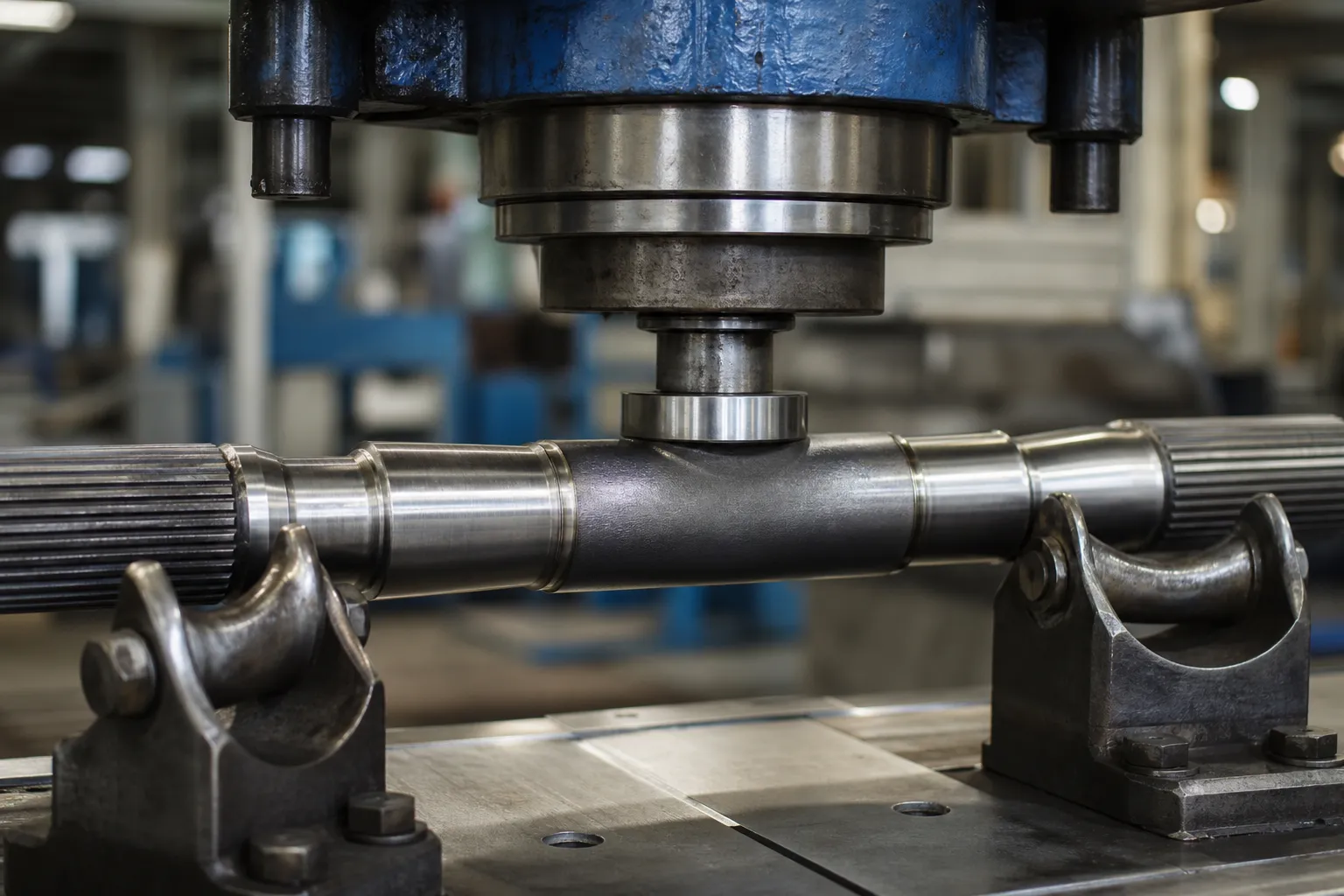
Sequence multi-bend parts deliberately. With an S-bend, correcting the largest lobe first and re-measuring before the next stroke prevents the two lobes from being pressed into a steeper local kink. The control system should enforce a re-measure between strokes rather than relying on a fixed recipe.
Critérios de Aceitação: O que “Bom” Means on the Drawing
Acceptance for this family is usually written as a set of runout limits at named stations, not a single global straightness number. A workable specification for a barrel before joint assembly typically covers:
- Total indicator reading at each bearing or bush seat, typically specified in the tens of micrometers on passenger-car parts and looser on commercial-vehicle shafts.
- Runout at the spline minor diameter or at a defined checking diameter adjacent to the spline, because this is what the joint concentricity inherits.
- End-face runout of welded flanges where present.
- For tripod stubs, the controlled trunnion-to-axis or axis-to-trunnion relationship from the drawing, plus spacing or phase where specified.
The acceptance method must also state the measuring condition: posições de apoio, clamping state, probe stations and the number of measurement planes. A machine acceptance that cannot be reproduced on the customer’s gauge will generate disputes that have nothing to do with the parts. Our articles on straightness versus runout versus TIR e sample-test acceptance for straightening machines describe how to write this correlation into the FAT protocol.
Common Pitfalls Seen in CV and Tripod Straightening Projects
| Pitfall | What Goes Wrong | Prevention |
|---|---|---|
| Straightening the greased assembly | Roller stack clearance contaminates every reading; correction lands on the wrong component | Straighten bare components upstream of joint assembly |
| Locating from spline tips or center holes | Datum errors of the same order as the tolerance | Functional-diameter or pitch-circle location with dedicated masters |
| One big press stroke | Local yield, dents on thin tubes, hardened-zone cracking | Multi-stroke correction with remeasure and springback compensation |
| Pressing on raceways or trunnion seats | Subsurface damage that survives inspection and fails in the field | Protected-zone map agreed with design engineering before cycle programming |
| Confusing runout with unbalance | Parts re-straightened endlessly chasing a balance problem | Separate geometric straightening from downstream dynamic balancing |
| Ignoring twist | Spline phase scrap discovered only at assembly | Add a twist check to the measurement routine and sort, not press |
From Distortion Data to a Machine Concept
A supplier asking for a CV or tripod shaft straightening solution should be prepared to share part drawings, the heat-treatment and welding route, a distortion census with distribution data, and the acceptance gauge definition. From that package the machine concept follows: number of measuring stations and probes, correction points and stroke capacity, tooling for the protected zones, and the data interface to the plant quality system. Where volumes justify it, the same cell can sort parts into rework classes instead of pressing every part the same way, which protects both cycle time and part integrity.
The economics are usually decided upstream: every welding, heat-treatment or handling step eliminated removes distortion that would otherwise have to be pressed out later. The straightening machine is the controlled, measurable response to the distortion the process cannot avoid, and it performs best when the process around it is honest about where the bends come from.