
Soluções de endireitamento de tubos de perfuração de petróleo
O tubo de perfuração de petróleo é o equipamento principal para perfuração de petróleo, e sua retidão e coaxialidade afetam diretamente a eficiência e segurança da perfuração. Nossa solução de endireitamento adota equipamento de endireitamento inteligente em grande escala equipado com sistema de medição a laser de alta precisão para garantir que a precisão de endireitamento e coaxialidade de todos os tipos de tubos de perfuração de petróleo atendam aos requisitos dos padrões API, o que melhora significativamente a vida útil das ferramentas de perfuração e a eficiência da perfuração.
Aplicação de tubo de perfuração de petróleo

Tubo de perfuração padrão
O tubo de perfuração padrão é a ferramenta de perfuração mais comumente usada na perfuração de petróleo e precisa garantir excelente coaxialidade e retilineidade para melhorar a eficiência da perfuração.
Aplicativo:
- Tubo de perfuração padrão API
- haste de perfuração para poços profundos
- Pólo de perfuração de poço direcional
- Pólo de perfuração de poço horizontal
Parâmetros técnicos:
- Coaxialidade: ≤0,08 mm/m
- Retidão: ≤0,2 mm/m
- Redondeza: ≤0,1 mm
- Eficiência de produção: 15-20 peças/hora
Tubo de perfuração especial
Tubos de perfuração especiais são usados em condições geológicas especiais e ambientes de trabalho complexos, que exigem propriedades de material mais altas e precisão de processamento.
Aplicativo:
- perfuração de poços ultraprofundos
- Poço O contendo enxofre
- Perfuração de poço de alta pressão
- Perfuração em piso duro
Parâmetros técnicos:
- Coaxialidade: ≤0,05 mm/m
- Retidão: ≤0,15 mm/m
- Redondeza: ≤0,1 mm
- Eficiência de produção: 10-15 peças/hora

Tool Joint Bends and Whole-Pipe Straightening
The tool joints at each end of a drill pipe are friction-welded, thick-wall forged sections carrying the API connections — the stiffest part of an already stiff assembly. In practice they almost never bend alone: when inspection flags runout or bend at a tool joint, the actual curvature usually lives in the pipe body near the weld transition or in the body-to-joint interface, and the correction is performed on the whole pipe with the joints in place. Straightening a tool joint in the workshop sense therefore means whole-pipe straightening, measured at the joints.
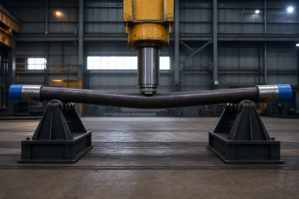
That measurement point matters. A straightened drill pipe is accepted at the connection: the runout between the joint thread axis and the pipe body axis is what runs true in the string, so the inspection datum is the joint even when the press acts on the body meters away. The correction route follows the press-versus-roll logic explained in our endireitamento de prensa vs endireitamento de rolo comparação, with thread protectors installed before any contact and support spacing set from the measured bend map rather than from pipe length habits.
Sequence is the other half of the story. Oilfield inspection contractors describe reconditioning flows in which straightening comes first, before cleaning and the subsequent wall-thickness, drift and crack surveys — the geometry has to be restored before those inspections produce meaningful results (reported service-sequence descriptions from drill pipe reconditioning providers). For the heavier BHA members below the pipe, correction logic escalates in force class: veja nosso endireitamento do colar de perfuração e endireitamento de tubo de perfuração pesado pages for the transition-zone and collar families.
Two practical rules keep tool-joint-related straightening out of trouble. Primeiro, protect the connections before anything else: thread protectors stay on during measurement and pressing, and no support, roller or clamp ever bears on a shoulder, thread or rotary-shoulder seal face — the connection is the most valuable and least repairable feature on the pipe. Segundo, treat the friction-weld zone as its own inspection item: a bend concentrated near the weld should trigger crack inspection of the transition area before any press cycle, because that zone carries both weld residual stresses and the section change that concentrates service bending. A pipe that passes a straightness check but carries a damaged connection or an uninspected weld anomaly has not been reconditioned — it has only been made harder to reject.
Twisted Pipe Is Not Bent Pipe — the Twist-Off Judgment
Drill pipe accumulates two different kinds of geometric damage, and only one of them belongs on a press. UM dobrar is deviation in a single plane — the tube reads straight from two perpendicular viewpoints and curved from the others. UM torção is permanent angular displacement around the pipe’s own axis: scribe a longitudinal line down a twisted joint and the line rotates as it travels — one cross-section has permanently rotated against its neighbors. The distinction matters because the two conditions come from different events and leave different damage behind.
Permanent twist is usually an accident record: twist-off events, where the string’s stored torsional energy releases at parting and winds the pipe beyond yield, plus stuck-pipe back-offs and the sustained torque of directional work. By the time the twist is visible, the affected length has already been loaded past yield in torsion — a metallurgical fact, not a geometry problem: no press cycle unwinds it, and rotating the section back cold would add a second plastic episode on top of the first.
This is why press straightening, as a process, declines the job. A straightening press superimposes controlled single-plane bending; twist correction would instead require controlled torque about the axis across the twisted length — a different machine and loading mode — while the yield history that produced the twist remains in the steel either way. The judgment that does apply runs:
- Quantify the twist first. Mark or measure the angular reference along the joint — how many degrees over what length — before any decision, the same measure-first discipline that governs bending.
- Treat visible permanent twist as a material flag. It marks a length that has already yielded once in service — a condition for the inspection standard to evaluate, not a shape to correct.
- Check the connections specifically. A joint that took twist concentrates consequences at the rotary shouldered connections, where make-up reference and shoulder sealing are compromised independently of the body — damage that routes to re-machining or replacement decisions, não para a imprensa.
- Route the verdict to the inspection standard. Whether a twisted joint is downgraded, restricted or condemned is decided under the governing inspection practice for drill stem elements — the framework mapped in our API straightness standards overview — not in the shop.
The practical consequence for reconditioning flow: twist is screened out at incoming inspection, before the joint is ever scheduled for press time. That sequencing — classify, then correct only what classification releases — is the organizing principle of our drill pipe reconditioning workflow article. A shop that discovers twist after straightening has wasted press time on a joint that was never a candidate.
One borderline case deserves honesty: a joint can carry both a bend and a mild residual twist, and the bend alone is legitimately correctable. Correct only what measurement defines — plane-by-plane bend correction to the connection-axis datum, with the twist documented and routed to the inspection decision — never “improved” by pressing harder in a diagonal plane.
The RSC Thread Axis Is the Straightness Datum
Ask where straightness is measured on a drill pipe joint and the wrong answer is the most common one: the outside surface of the tube. A chalk line along the OD can read straight while the joint still runs out in the string, and a joint with a visible body bow can run true — because the pipe’s functional axis is not its skin. It is the axis established by the rotary shouldered connections at both ends. The RSC thread axis is the datum the string actually rotates about, and every straightening measurement that matters is taken against it.
The reasoning is mechanical. Em serviço, the joint’s position in the drill string is defined entirely by its two connections: shoulders seat, threads engage, and the next joint’s axis continues from the connection axis, not from the mid-body OD. What the rig experiences as “crooked pipe” is eccentricity between those connection axes and the tube between them. A body-straightening pass judged on surface lines can leave that eccentricity untouched — the tube looks better and the string vibrates exactly as before.
Measurement practice follows the datum:
- Simulate the thread axis at both ends. Thread-mounted arbors, expanding mandrels or precision centering in the connection bore stand in for the axis the threads define, and runout is read off the tube body against that simulated axis.
- Or invert the reference. With the joint supported on the connection datum surfaces, body runout is measured directly along the tube — support geometry substitutes for arbors when they are not available, at some cost in setup rigor.
- Read at defined stations, not at the worst-looking spot. A runout profile along the body — the multipoint logic described in our multipoint shaft measurement article — is what turns “it looks straight” into a number the certification can carry.
The connection-inspection world already maintains a mature gauge ecosystem for RSC geometry — thread single-element and gauging practice for taper, lead and form — and straightening acceptance should be understood as one branch of that same connection-defined metrology. The gauges certify the connection; the runout check certifies the body against the connection’s axis; together they answer the only question the string asks: does this joint run true about the axis its threads define?
On the press, the datum has two operational consequences. Supports and press points are chosen so the correction acts on the body without ever loading a connection, and the post-correction verification is taken on the connection-axis datum before the joint is released — shop-floor acceptance and string-level acceptance stay the same measurement, as outlined for tubular repair work in our drill pipe reconditioning workflow. A straightening record that shows body runout measured to the RSC axis is the one a recertification file can defend; anything measured to a surface line is geometry documentation, not acceptance.
Vídeo do processo da solução de endireitamento de tubos de perfuração de petróleo
Características do produto para máquina de endireitamento de tubos de perfuração de petróleo
- Para garantir a precisão do teste, use um sensor de deslocamento de alta precisão ao construir e processar acessórios de teste.
- Equipado com sistema de carregamento de controle de posição de alta precisão para melhorar a precisão do alinhamento.
- Coordenar e gerenciar os vários componentes para encurtar o ritmo do processo de alisamento.
- Informações perfeitas de alerta de alarme de situação anormal para facilitar a manutenção do equipamento.
- possui um cartão de memória de 16g para armazenar informações de processamento, link de comunicação reservado com o computador host.
- Ferramentas e acessórios de troca rápida, ajuste e mudança parametrizados, configuração de ferramenta automatizada.


