
Múltiplas leituras de deslocamento podem transformar uma inspeção de eixo longo de um único pico em um mapa de erro. Esse valor depende de mais do que o sensor: geometria de suporte, assento de referência, contato da sonda, rotação/indexação, sincronização, as condições ambientais e a regra de cálculo afetam o que está sendo relatado.

*Ilustração do conceito de engenharia. Não é uma especificação de sensor, sistema instalado ou resultado de medição verificado.*
Defina a característica antes de selecionar sensores
Primeiro indique se a característica de aceitação é a retilineidade da linha central, arco local, desvio em relação a um dado, desvio de perfil ou outro resultado controlado. Um traço de tensão ou deslocamento do sensor não é por si só o requisito do cliente. O plano de inspeção deve identificar características de referência, suporta, estações, orientações, período, cálculo, unidades, limites e o estado em que a peça é aceita.
| Elemento | Pergunta para fechar |
|---|---|
| Dado | Quais recursos estabelecem o eixo ou superfície de referência? |
| Apoiar | Ele replica a condição do cliente ou da peça liberada? |
| Caminho da sonda | Os pontos de contato são superfícies funcionais e protegidos contra danos? |
| Estações | Eles capturam zonas de curvatura conhecidas e transições de recursos? |
| Rotação/indexação | Como a orientação é preservada entre as leituras? |
| Cálculo | Como as leituras são convertidas na característica controlada? |
Para controles de dados, ver limpeza do furo central do eixo e preparação de referência e repetibilidade do dispositivo e assento de referência.
How an LVDT Works, and Why Its Physics Matters
The linear variable differential transformer earns its place on production machinery through a short list of physical virtues. Inside the housing, a primary coil is excited with an alternating current, and two secondary coils sit either side of it; a ferromagnetic core, attached to the probe tip by a slim push rod, slides along the axis. With the core centered, the induced voltages in the two secondaries balance; displace the core and the balance tips in proportion to the movement. The electronics read the amplitude and phase of that imbalance and report displacement. Because the core never touches the coils, there is no friction or wear inside the sensor; because the coupling is inductive, the reading is largely indifferent to dust, oil mist and humidity that blind optical sensors; and because the moving mass is small, the tip can follow moderate surface motion faithfully. The trade-offs are equally physical: it needs signal conditioning and calibration against a reference, the raw output is relative rather than absolute, and the probe tip itself is a mechanical component with its own condition, force and wear story.
Where Errors Enter Between Probe and Number
Treating the chain as one system, as the section above demands, means knowing the specific doors through which error walks in. Thermal drift: the sensor body, the fixture and the part all expand and contract with temperature, and on a machine that warms through a shift, a morning zero and an afternoon reading are not the same event — hence reference checks on a master at intervals the procedure defines. Mounting: a probe on a long, unsupported bracket is a cantilever with its own compliance, and vibration or cable pull moves the whole assembly relative to the part, indistinguishable from part movement in the data. Dynamics: when the part or probe moves during scanning, the stylus mass and tip force set a speed limit beyond which the tip skips or lags, writing false features into the trace. Contact condition: tip wear flattens the intended radius and changes where the reading sits on a curved surface. None of these is exotic; each is controlled by written procedure — zero method, master check interval, scan speed, tip inspection — which is precisely what the validation framework above asks the system description to contain.
Trate a cadeia de medição como um sistema
Um LVDT pode ser adequado para deslocamento relativo, mas o resultado medido também inclui a montagem do sensor, deflexão do aparelho, condicionamento de sinal, tempo, assento da peça e comportamento do operador ou automação. Registre cada elemento da cadeia para que uma mudança posterior no resultado possa ser investigada.
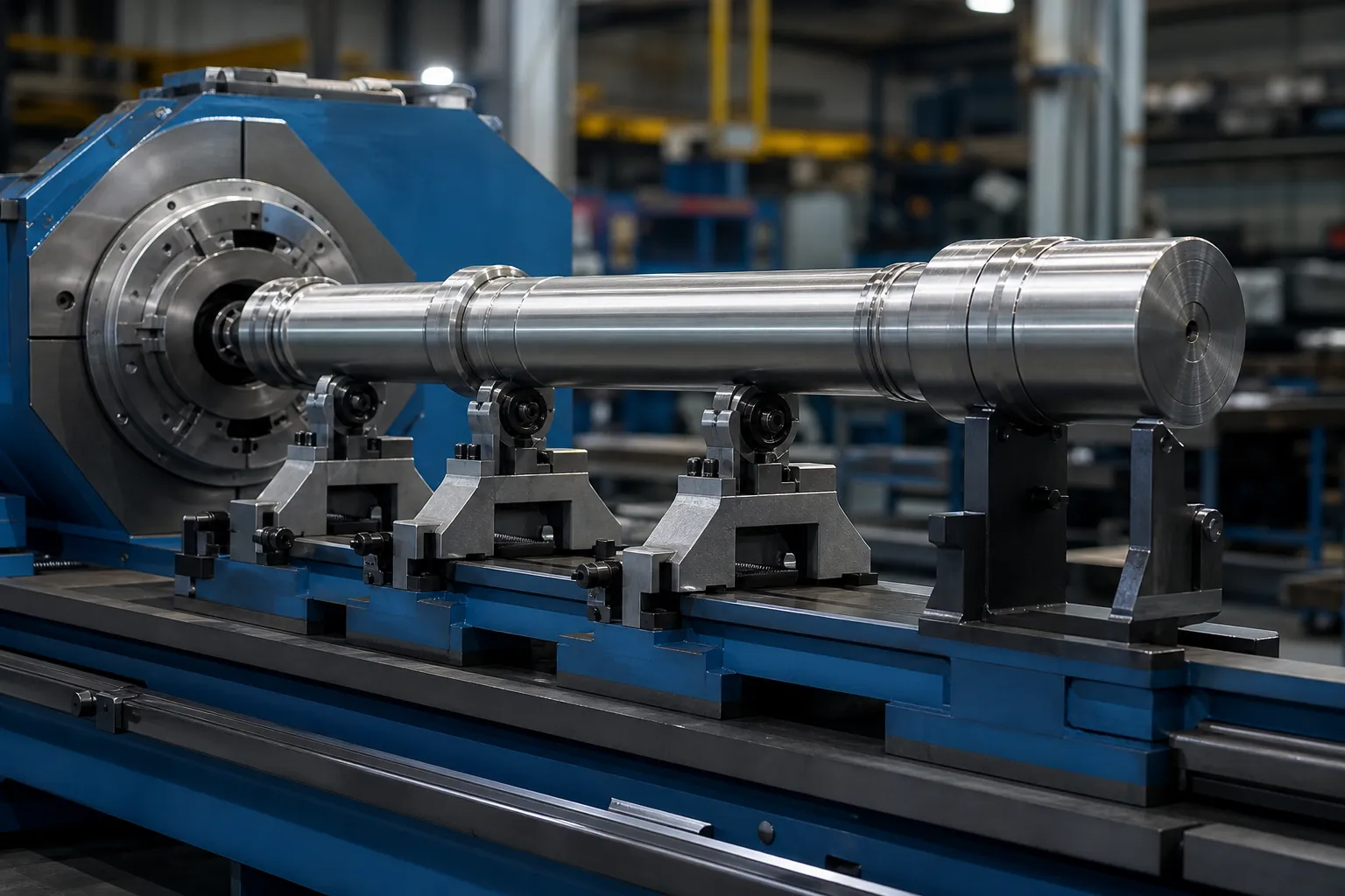
*Ilustração do conceito de engenharia. Rigidez do dispositivo, a posição e a proteção do sensor exigem engenharia específica do projeto.*
O procedimento controlado deve abranger a identificação do sensor, referência/verificação mestre, condição de montagem, proteção de cabo, método zero, orientação da amostra, apoiar a limpeza, configurações de aquisição de dados e retenção de dados. Uma leitura repetida de um aparelho instável não é evidência de repetibilidade.
Sincronizar localização, Orientação e Leituras
Os dados multiponto são úteis apenas quando cada valor pode ser atribuído a uma posição e condição conhecida. Se a peça girar ou se mover, definir o codificador/índice, coordenada da estação, direção de viagem, condição de permanência ou amostragem, e o que acontece se faltar um sinal. O resultado deve preservar os dados de origem brutos ou rastreáveis necessários para reconstruir o mapa.
Evite interpretar um pico localizado sem verificar o assentamento e o contato. Reposicionar testes, orientação invertida quando apropriado e leituras repetidas da linha de base podem distinguir uma característica da peça de uma indicação falsa.
Choosing Station Count and Placement
How many stations, and where, is a geometry question before it is a budget question. The error modes of slender parts are smooth in space: a bend is a low-frequency curve, so a modest number of stations — placed where the physics says the information lives — reconstructs it well, while doubling the count in uninformative positions buys data volume, not accuracy. Informative positions are predictable: mid-span between supports where a bow reaches its excursion; each stiffness transition on stepped parts, where peaks like to hide; immediately beside functional features whose relationship to the datum matters; and the free ends, which anchor the map. The failure mode of sparse placement is aliasing in its practical form — a short kink sitting between two stations contributes to neither reading cleanly, and a correction aimed at the reconstructed map presses in the wrong place. The honest way to close this risk is not infinite density but a validation: map a set of parts at high density once, confirm that the production station set reconstructs the same peaks and amplitudes, and document that comparison as the station-plan justification.
Turning the Map Into a Correction Decision
The map exists to drive action, and its action vocabulary has three entries: where to press, in which direction, and how hard to expect the part to respond. Peak position and direction come from comparing stations around the maximum; on a part rotating between stations, preserving angular indexing — the synchronization discipline above — is what converts separate readings into a vector, not a pile of magnitudes. Expected response comes from the stiffness story the map already tells: a peak on a heavy section needs a different correction plan than the same amplitude on a thin one, and peaks at stiffness transitions deserve the respect described for separating bend from roundness and setup effects before any press follows. What the map must not do is trigger correction on unverified signals: a localized reading that has not survived a reseat check is a hypothesis, not a peak. That guard rail — map, verificar, then correct, with released-state measurement closing the loop — is the same sequence that makes automatic shaft straightening converge in few strokes instead of many.
Correlacionar com a aceitação da peça liberada
A medição durante a fixação ou correção pode ser útil para controle de processo, mas não prova automaticamente que o eixo liberado atende ao requisito. Compare o método de linha com um método de peça liberada aprovado em amostras representativas em toda a variação normal. Ver medição de retilinidade carregada versus liberada para o limite.
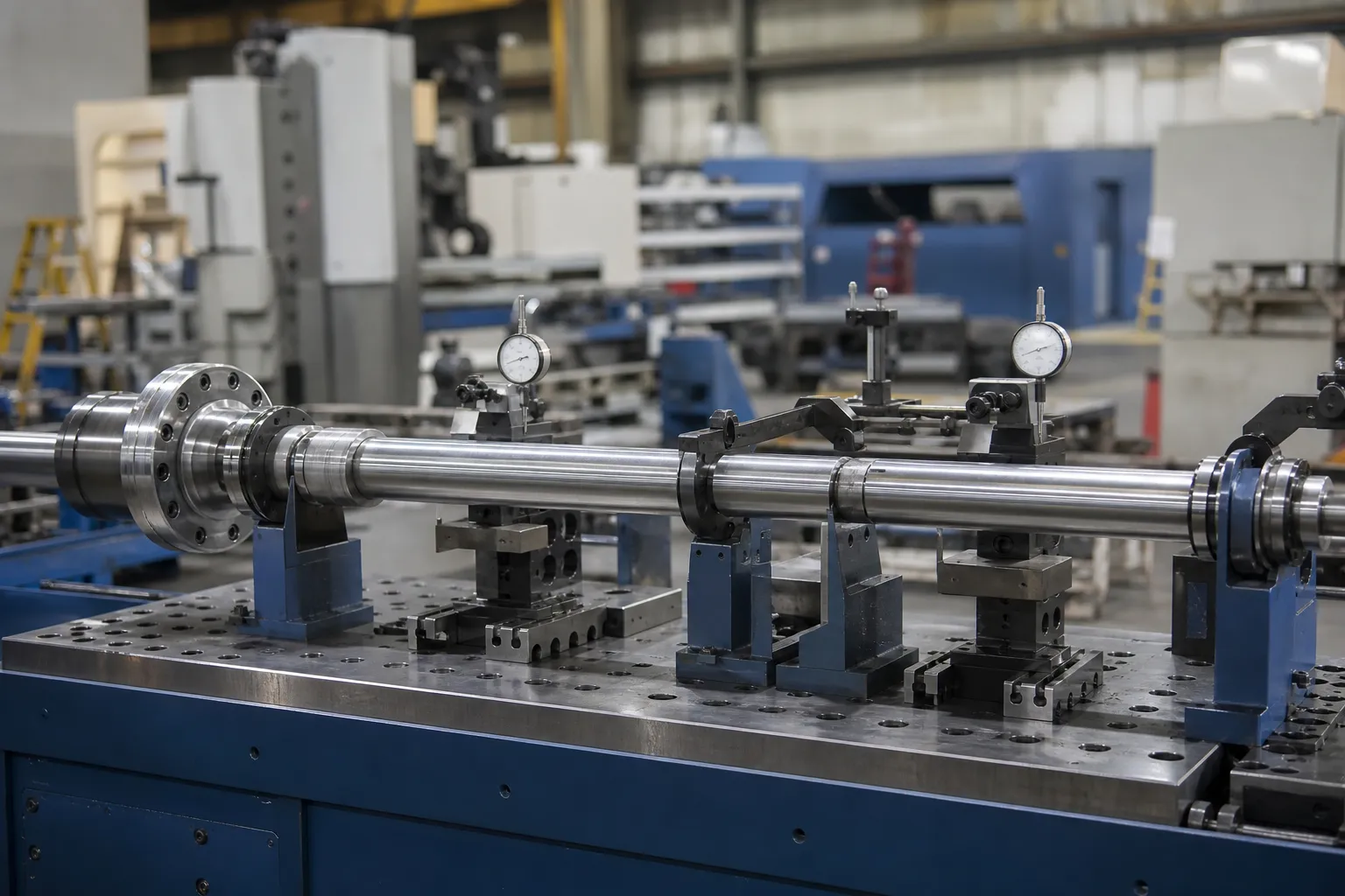
*Ilustração do conceito de engenharia. O método de referência, os suportes e o cálculo de aceitação devem ser controlados pelo plano de qualidade aprovado.*
Um plano de correlação deve definir amostras correspondentes, comparação cega quando for prático, equivalência de dados/suporte, status de calibração, revisão de preconceito, revisão de repetibilidade/reprodutibilidade, diferença permitida, regras de escalonamento e controle de mudanças. Consulte correlação entre medidor da máquina e medidor do cliente e medidor R&R para endireitar linhas.
Entradas necessárias para um estudo de medição
Forneça o desenho e a definição da característica, método de inspeção existente, geometria da peça e recursos de referência, estágio de material/fabricação, locais de curvatura esperados, população amostral, restrições ambientais, registro de dados desejado e método de aceitação do cliente. Use o teste de amostra de endireitamento e guia de aceitação para estabelecer o registro do julgamento, então entre em contato com StraighteningTech para uma discussão sobre aplicação.
Validação necessária antes de uma reclamação do sistema
Any multi-point measurement claim needs a defined probe and datum setup, referências calibradas, repeated or reseated readings on representative parts, and customer-gauge correlation. A generic machine capability is not a verified result.
Perguntas frequentes
Does adding more measurement stations automatically improve accuracy?
Não. Stations placed where the geometry has information — mid-span peaks, stiffness transitions, functional features, ends — improve the map. Stations added elsewhere add data volume and cost while leaving reconstruction essentially unchanged. Validate the chosen set once against a dense map and document the comparison.
Why do LVDT readings drift over a production shift?
Most often thermal: sensor, fixture and part expand at different rates as the cell warms, shifting the zero. Mechanical causes come next — bracket compliance, cable pull, tip wear. The control is procedural: a defined zero method and reference-master checks at set intervals, with any shift beyond the procedure’s limit triggering investigation rather than quiet re-zeroing.
Can multipoint LVDT data replace final inspection?
Only through correlation. In-process multipoint data drives the correction loop; the acceptance decision belongs to the released-state method the customer recognizes. When the two have a documented correlation on representative parts, the line method gains standing — until then it is process control, not release.
Recursos relacionados à tecnologia de alisamento
Ver como funciona o endireitamento automático do eixo, endireitando teste de amostra e aceitação e retilineidade do eixo vs desvio vs TIR para limites de controle genéricos que se aplicam antes de qualquer reivindicação de capacidade Medição de eixo multiponto LVDT.
Multipoint measurement pays off at acceptance time – pair the Lista de verificação FAT with the GD&T straightness acceptance guide to agree measurement method and tolerance interpretation in one pass.