
Wielokrotne odczyty przemieszczenia mogą zamienić kontrolę długiego wału z pojedynczego szczytu w mapę błędów. Wartość ta zależy od czegoś więcej niż tylko czujnika: geometria wsparcia, miejsce odniesienia, kontakt sondy, rotacja/indeksowanie, synchronizacja, warunki środowiskowe i zasada obliczeń mają wpływ na zgłaszane informacje.

*Ilustracja koncepcja inżynierii. To nie jest specyfikacja czujnika, zainstalowany system lub zweryfikowany wynik pomiaru.*
Zdefiniuj charakterystykę przed wyborem czujników
Najpierw określ, czy cechą akceptacji jest prostoliniowość linii środkowej, lokalny łuk, bicie względem punktu odniesienia, odchylenie profilu lub inny kontrolowany wynik. Wartość napięcia czujnika lub śladu przemieszczenia nie jest sama w sobie wymaganiem klienta. Plan inspekcji musi identyfikować elementy odniesienia, obsługuje, stacje, orientacje, przęsło, obliczenie, jednostki, limitów i stanu, w jakim dana część jest akceptowana.
| Element | Pytanie do zamknięcia |
|---|---|
| Fakt | Które elementy wyznaczają oś odniesienia lub powierzchnię? |
| Wsparcie | Czy replikuje stan klienta lub zwolnionej części?? |
| Ścieżka sondy | Czy punkty styku są powierzchniami funkcjonalnymi i chronionymi przed uszkodzeniami? |
| Stacje | Czy wychwytują znane strefy zagięć i przejścia? |
| Obrót/indeksowanie | W jaki sposób zachowana jest orientacja pomiędzy odczytami? |
| Obliczenie | W jaki sposób odczyty są przekształcane w kontrolowaną charakterystykę? |
Do kontroli punktów odniesienia, Widzieć czyszczenie centralnego otworu wału i przygotowanie punktu odniesienia I Powtarzalność osprzętu i osadzenie punktu odniesienia.
Jak działa LVDT, i dlaczego jego fizyka ma znaczenie
Liniowy transformator różnicowy o zmiennej charakterystyce zyskuje swoje miejsce w maszynach produkcyjnych dzięki krótkiej liście zalet fizycznych. Wewnątrz obudowy, cewka pierwotna jest wzbudzana prądem przemiennym, i dwie cewki wtórne znajdują się po obu jego stronach; rdzeń ferromagnetyczny, przymocowany do końcówki sondy za pomocą cienkiego popychacza, przesuwa się wzdłuż osi. Z rdzeniem wyśrodkowanym, indukowane napięcia w dwóch wtórnych równoważą się; przesuwaj rdzeń i końcówki balansu proporcjonalnie do ruchu. Elektronika odczytuje amplitudę i fazę braku równowagi i zgłasza przemieszczenie. Ponieważ rdzeń nigdy nie dotyka cewek, wewnątrz czujnika nie ma tarcia ani zużycia; ponieważ sprzęgło jest indukcyjne, odczyt jest w dużej mierze obojętny na kurz, mgła olejowa i wilgoć, które oślepiają czujniki optyczne; oraz dlatego, że poruszająca się masa jest mała, końcówka może wiernie podążać za umiarkowanym ruchem powierzchni. Kompromisy są równie fizyczne: wymaga kondycjonowania sygnału i kalibracji względem odniesienia, surowy wynik jest względny, a nie bezwzględny, a sama końcówka sondy jest elementem mechanicznym mającym swój własny stan, historia siły i zużycia.
Gdzie błędy pojawiają się pomiędzy sondą a numerem
Traktowanie łańcucha jako jednego systemu, jak wymaga tego sekcja powyżej, oznacza znajomość konkretnych drzwi, przez które wchodzi błąd. Dryft termiczny: korpus czujnika, uchwyt i część rozszerzają się i kurczą pod wpływem temperatury, oraz na maszynie, która nagrzewa się podczas zmiany, poranne zero i popołudniowy odczyt to nie to samo zdarzenie – stąd kontrole referencyjne wzorca w odstępach czasu określonych przez procedurę. Montowanie: sonda na długim, wspornik niepodparty jest wspornikiem posiadającym własną podatność, a wibracje lub ciągnięcie kabla przesuwają cały zespół względem części, nie do odróżnienia od ruchu części w danych. Dynamika: gdy część lub sonda porusza się podczas skanowania, masa igły i siła końcówki wyznaczają granicę prędkości, powyżej której końcówka przeskakuje lub pozostaje w tyle, zapisywanie fałszywych cech w śladzie. Stan kontaktu: zużycie końcówki spłaszcza zamierzony promień i zmienia się w miejscu, w którym odczyt znajduje się na zakrzywionej powierzchni. Żaden z nich nie jest egzotyczny; każdy jest kontrolowany metodą pisemną – metodą zerową, główny interwał sprawdzania, prędkość skanowania, inspekcja końcówek — dokładnie to ma zawierać powyższa struktura walidacji w opisie systemu.
Traktuj łańcuch pomiarowy jako jeden system
LVDT może nadawać się do względnego przemieszczenia, ale wynik pomiaru obejmuje również montaż czujnika, ugięcie oprawy, kondycjonowanie sygnału, chronometraż, osadzenie części oraz zachowanie operatora lub automatyki. Zapisz każdy element łańcucha, aby można było zbadać późniejszą zmianę wyniku.
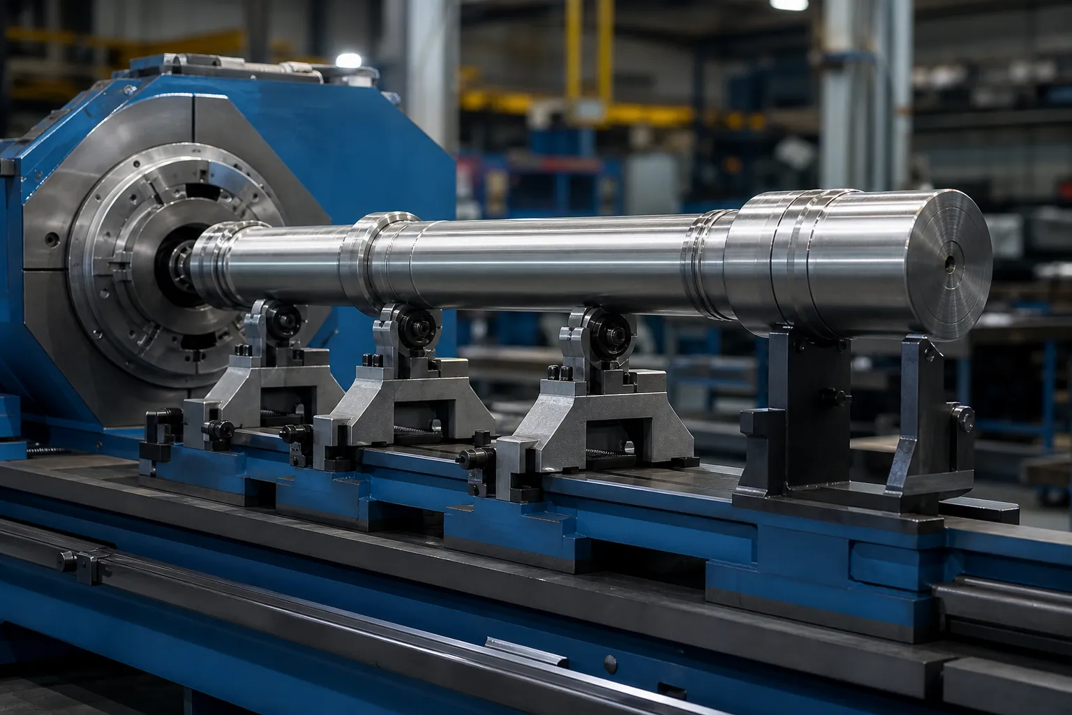
*Ilustracja koncepcja inżynierii. Sztywność mocowania, położenie czujnika i osłona wymagają inżynierii dostosowanej do konkretnego projektu.*
Kontrolowana procedura powinna obejmować identyfikację czujnika, referencja/kontrola główna, stan montażu, ochrona kabla, metoda zerowa, orientacja próbki, wspierać czystość, ustawienia gromadzenia i przechowywania danych. Powtarzający się odczyt z niestabilnego urządzenia nie jest dowodem powtarzalności.
Synchronizuj lokalizację, Orientacja i odczyty
Dane wielopunktowe są przydatne tylko wtedy, gdy każdą wartość można przypisać do znanej pozycji i warunku. Jeśli część obraca się lub porusza, zdefiniuj koder/indeks, współrzędna stacji, kierunek podróży, warunki przebywania lub pobierania próbek, i co się stanie, jeśli zabraknie sygnału. Wynik powinien zachować surowe lub możliwe do prześledzenia dane źródłowe potrzebne do zrekonstruowania mapy.
Unikaj interpretacji zlokalizowanego piku bez sprawdzenia osadzania i kontaktu. Ponowne testy, w stosownych przypadkach odwrócona orientacja i powtarzane odczyty linii bazowej mogą odróżnić cechę części od fałszywego wskazania.
Wybór liczby i rozmieszczenia stacji
Ile stacji, i gdzie, jest pytaniem o geometrię, zanim będzie to kwestia budżetu. Tryby błędów smukłych części są gładkie w przestrzeni: zagięcie to krzywa o niskiej częstotliwości, zatem skromna liczba stacji – umieszczonych tam, gdzie według fizyki znajduje się informacja – dobrze ją rekonstruuje, podwajając liczbę na pozycjach pozbawionych informacji, kupuje się ilość danych, nie dokładność. Stanowiska informacyjne są przewidywalne: w połowie rozpiętości między podporami, gdzie łuk osiąga swoje wychylenie; każde przejście sztywności na częściach schodkowych, gdzie szczyty lubią się ukrywać; bezpośrednio obok cech funkcjonalnych, których związek z punktem odniesienia ma znaczenie; i wolne końce, które zakotwiczają mapę. Tryb awaryjny rzadkiego rozmieszczenia to aliasing w swojej praktycznej formie - krótkie załamanie między dwiema stacjami nie przyczynia się do czystego odczytu, oraz poprawka mająca na celu umieszczenie zrekonstruowanej mapy w niewłaściwym miejscu. Uczciwym sposobem na zamknięcie tego ryzyka nie jest nieskończona gęstość, ale walidacja: jednokrotnie zmapuj zestaw części z dużą gęstością, potwierdzić, że zestaw stacji produkcyjnej rekonstruuje te same piki i amplitudy, i udokumentuj to porównanie jako uzasadnienie planu stacji.
Przekształcenie mapy w decyzję korygującą
Mapa istnieje, aby napędzać działanie, a jego słownictwo dotyczące działań zawiera trzy wpisy: gdzie nacisnąć, w jakim kierunku, i jak trudno oczekiwać, że część zareaguje. Pozycja i kierunek szczytu pochodzą z porównania stacji w pobliżu maksimum; na części obracającej się pomiędzy stacjami, zachowanie indeksowania kątowego — powyższa dyscyplina synchronizacji — przekształca oddzielne odczyty w wektor, a nie kupa wielkości. Oczekiwana reakcja wynika z historii sztywności, którą mówi już mapa: pik na ciężkim przekroju wymaga innego planu korekcji niż ta sama amplituda na cienkim, i szczyty przy przejściach sztywności zasługują na opisany szacunek oddzielanie zagięcia od okrągłości i efektów konfiguracji zanim nadąży za tym jakakolwiek prasa. Mapa nie może powodować korekcji niezweryfikowanych sygnałów: zlokalizowany odczyt, który nie przetrwał kontroli ponownego założenia, jest hipotezą, nie szczyt. Ta poręcz – mapa, zweryfikować, wtedy popraw, z pomiarem stanu zwolnionego zamykającego pętlę — jest to ta sama sekwencja, która powoduje automatyczne prostowanie wału zbiegają się w kilku ruchach zamiast w wielu.
Powiązane z akceptacją zwolnionej części
Pomiar podczas mocowania lub korekcji może być przydatny do kontroli procesu, ale nie oznacza to automatycznie, że zwolniony wał spełnia wymagania. Porównaj metodę liniową z zatwierdzoną metodą uwolnionej części na reprezentatywnych próbkach w normalnych warunkach. Widzieć pomiar prostoliniowości obciążonej i zwolnionej dla granicy.
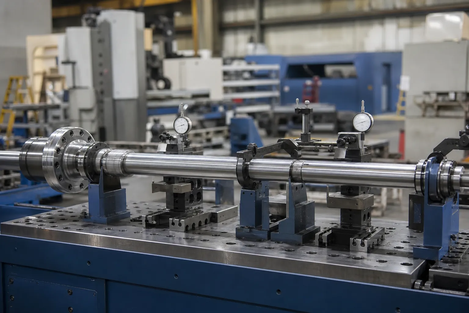
*Ilustracja koncepcja inżynierii. Metoda referencyjna, podpory i obliczenia akceptacji muszą być kontrolowane przez zatwierdzony plan jakości.*
Plan korelacji powinien definiować dopasowane próbki, ślepe porównanie, jeśli jest to praktyczne, równoważność podstawy/podpory, stan kalibracji, recenzja stronniczości, przegląd powtarzalności/odtwarzalności, dozwolona różnica, zasady eskalacji i kontroli zmian. Patrz korelacja miernika maszyny z miernikiem klienta I miernik R&R do prostowania linii.
Dane wejściowe potrzebne do badania pomiarowego
Podaj rysunek i definicję charakterystyki, istniejąca metoda kontroli, geometria części i elementy bazowe, etap materiału/produkcji, oczekiwane miejsca zagięcia, próbna populacja, ograniczenia środowiskowe, żądany zapis danych i sposób akceptacji klienta. Skorzystaj z Próbny test prostowania i przewodnik akceptacji w celu ustalenia protokołu rozprawy, Następnie skontaktuj się z StraighteningTech do dyskusji na temat aplikacji.
Wymagana weryfikacja przed roszczeniem systemowym
Każdy wniosek dotyczący pomiaru wielopunktowego wymaga zdefiniowanej konfiguracji sondy i punktu odniesienia, kalibrowane odniesienia, powtarzane lub ponownie umieszczane odczyty na reprezentatywnych częściach, oraz korelacja wskaźnika klienta. Ogólna wydajność maszyny nie jest zweryfikowanym wynikiem.
Często zadawane pytania
Czy dodanie większej liczby stanowisk pomiarowych automatycznie poprawia dokładność??
NIE. Stacje umieszczone tam, gdzie geometria zawiera informacje — szczyty w połowie rozpiętości, przejścia sztywności, cechy funkcjonalne, kończy się — ulepsz mapę. Stacje dodane gdzie indziej zwiększają ilość danych i koszt, pozostawiając rekonstrukcję zasadniczo niezmienioną. Zweryfikuj raz wybrany zestaw na gęstej mapie i udokumentuj porównanie.
Dlaczego odczyty LVDT zmieniają się podczas zmiany produkcyjnej??
Najczęściej termiczne: transduktor, uchwyt i część rozszerzają się z różną szybkością w miarę nagrzewania się ogniwa, przesunięcie zera. Następne są przyczyny mechaniczne – zgodność zamka, ciągnięcie kabla, zużycie końcówki. Kontrola ma charakter proceduralny: zdefiniowana metoda zerowania i kontrole wzorcowe w ustalonych odstępach czasu, przy czym każde przesunięcie poza limit procedury powoduje rozpoczęcie dochodzenia zamiast cichego ponownego zerowania.
Czy wielopunktowe dane LVDT mogą zastąpić kontrolę końcową??
Tylko poprzez korelację. Wielopunktowe dane w procesie sterują pętlą korekcyjną; decyzja o akceptacji należy do metody stanu zwolnionego, którą rozpoznaje klient. Kiedy oba mają udokumentowaną korelację w reprezentatywnych częściach, metoda liniowa zyskuje na popularności – do tego czasu jest to kontrola procesu, nie zwolnić.
Powiązane zasoby dotyczące technologii prostowania
Widzieć jak działa automatyczne prostowanie wału, badanie próbki prostowania i akceptacja I prostość wału vs bicie vs TIR dla ogólnych granic kontroli, które mają zastosowanie przed jakimkolwiek żądaniem zdolności Wielopunktowy pomiar wału LVDT.
Pomiar wielopunktowy opłaca się już w momencie akceptacji – sparuj Lista kontrolna FAT z GD&T przewodnik akceptacji prostoliniowości uzgodnienie metody pomiaru i interpretacji tolerancji w jednym przejściu.