
Obrotowy ślad wskaźnika może zawierać kilka efektów jednocześnie. Może odzwierciedlać oś przedmiotu obrabianego, lokalna okrągłość, forma cylindryczna, związek odniesienia, siedzenia wspierające, błąd oprawy, konfiguracja sondy lub przerwana funkcja. Nazywanie każdego wysokiego odczytu „zgięciem” może prowadzić do niewłaściwych działań korygujących i może uszkodzić część, która faktycznie wymaga przeglądu pomiaru lub obróbki.
W tym przewodniku wyjaśniono, jak zdiagnozować sygnał przed podjęciem decyzji o wyprostowaniu. Nie ustanawia systemu pomiarowego StraighteningTech, tolerancja, rozdzielczość czujnika, procedura odniesienia lub możliwość korekcji. Do podjęcia ostatecznych decyzji wymagany jest kontrolowany rysunek i metoda kontroli klienta.
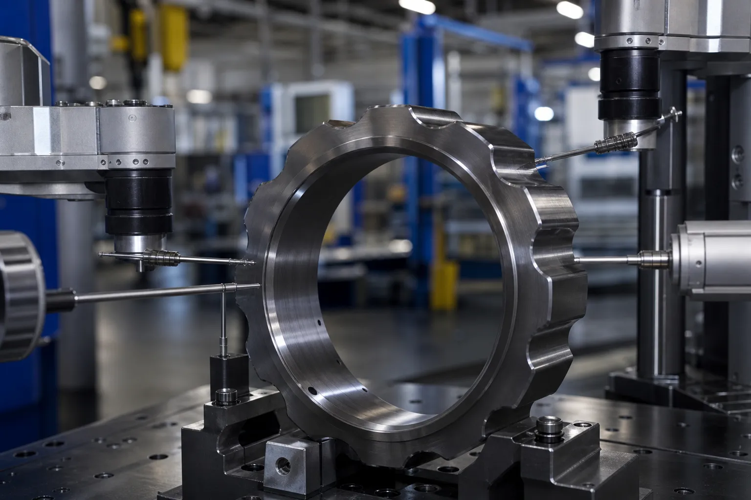
*Ilustracja koncepcja inżynierii. Pokazuje, że sygnał obrotowy może obejmować zmianę kształtu; nie jest to wynik pomiaru części klienta ani zalecana konfiguracja inspekcji.*
Nazwij cechę przed odczytaniem miernika
Zaokrąglenie opisuje stan kształtu przekroju poprzecznego. Zagięcie osi opisuje przestrzenną ścieżkę osi odniesienia. Bicie to pomiar rotacyjny względem układu odniesienia i może obejmować wielu czynników. Współosiowość, koncentryczność i walcowość również mają różne definicje i wymagania kontrolne. Rysunek musi wskazywać, która cecha kontroluje akceptację.
| Sygnał lub charakterystyka | Pytanie diagnostyczne |
|---|---|
| Okrągłość / lobowanie | Czy promień lokalny zmienia się wraz z obrotem przekroju?? |
| Zagięcie osi | Czy oś odniesienia zmienia położenie na długości? |
| Wybicie | Które dane, wsporniki i stacja sondy tworzą odczyt? |
| Relacja koncentryczna | Czy wiele obiektów jest porównywanych do określonej wspólnej osi? |
| Sygnał urządzenia | Czy ponowne osadzenie lub zmiana orientacji podpory zmienia wynik?? |
Widzieć prostość wału, bicie i TIR I współosiowość a bicie dla powiązanej terminologii.
Z czego składa się ślad obrotowy
Odczyt sondy wykonywany podczas obracania się części, matematycznie, mieszanka składników, które powtarzają się raz, dwa razy, trzy razy i więcej na obrót. Czytanie mieszanki jest podstawową umiejętnością diagnostyczną. Składowa występująca raz na obrót oznacza, że powierzchnia jest, średnio, dalej od osi obrotu z jednej strony niż z drugiej — co jest oznaką przesunięcia osi pomiędzy geometrią odniesienia części a osią obrotu, lub wygiętej osi przemieszczającej przekrój jako całość. Dwa razy- lub składnik trzykrotny na obrót oznacza, że przekrój jest owalny lub karbowany: sam promień lokalny zmienia się na obwodzie, stan kształtu przekroju poprzecznego, którego nie usuwa żadna korekta osi. Treści o wyższej częstotliwości zwykle odzwierciedlają teksturę powierzchni, rowki wpustowe i elementy przerywane, lub wibracje przedostające się przez podpory.
Zdecydowany podział pomiędzy dwiema przyczynami związanymi z obrotem raz na obrót ma charakter osiowy. Prawdziwy zakręt przemieszcza różne stacje w różnym stopniu i często w różnych kierunkach, zatem amplituda i faza składowej występującej raz na obrót zmieniają się w miarę przesuwania się sondy wzdłuż części. Stan czystej mimośrodowości — przesunięcie środków, przesunięcie siedzenia, bicie uchwytu — wytwarza składową raz na obrót, która utrzymuje tę samą fazę i proporcjonalną amplitudę na każdej stacji. Jeden ślad na jednej stacji nie jest w stanie ich rozróżnić; krótka mapa osiowa zwykle może. Takie jest uzasadnienie powyższej dyscypliny wielostanowiskowej, i za wielopunktowe układy pomiarowe odczytujące kilka stacji w jednej konfiguracji.
Skąd się bierze lobbing
Lobowanie rzadko jest przypadkowe — niesie ze sobą odcisk palca obróbki, która wytworzyła powierzchnię, co czyni go diagnostycznym. Trójlistkowa nieokrągłość to klasyczna cecha części szlifowanych na maszynach bezkłowych, gdzie część unosi się pomiędzy kołem, regulujące i ostrze, a geometria blokuje się w stanie trzypunktowej stabilności. Owalność równomiernych płatków wynika z przeciwnego zaciśnięcia lub odkształcenia złagodzonego po obróbce — cienka tuleja zwolniona z uchwytu, część, która uległa rozluźnieniu po obróbce cieplnej. Dziwne występy powyżej trzech pojawiają się w przypadku pewnych układów mocowania i nawrotów przerwanych cięć. Znajomość trasy procesu części mówi zatem, jakiego lobowania się spodziewać i czy zaobserwowana liczba lobów jest rzeczywistością przedmiotu obrabianego, czy artefaktem bieżącej konfiguracji: konfiguracja generuje liczbę płatków, która zmienia się po ponownym osadzeniu części w różnych orientacjach, nie ta część.
Najpierw sprawdź odniesienie i konfigurację
Przed interpretacją części, sprawdź funkcje centrum, czopy lub inne powierzchnie odniesienia, warunek wsparcia, czystość, kontakt sondy, metoda obrotowa i stacja osiowa. Uszkodzony środek, bełkotać, brudne siedzenie, nieprawidłowe podparcie lub kontakt sondy na przerwanej powierzchni może spowodować widoczne bicie, które nie odzwierciedla wygięcia osi.
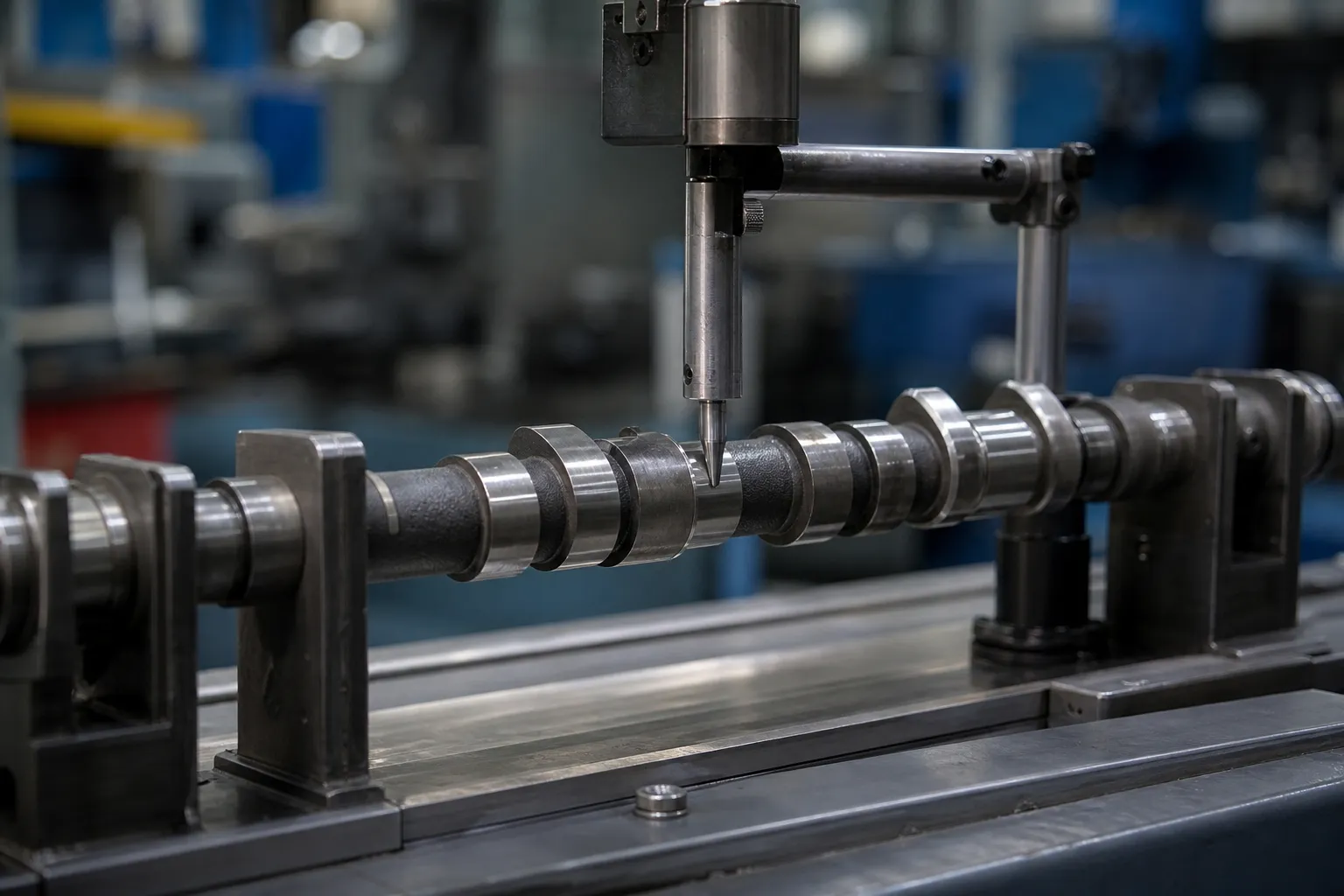
*Ilustracja koncepcja inżynierii. Ilustruje pomiar dziennika uwzględniający funkcje; rzeczywiste dane, tory sondy i maski kątowe zależą od kontrolowanego przedmiotu.*
Skorzystaj z funkcji ponownego włączenia/powtórzenia i porównaj wiele stacji. Jeśli ślad ulegnie znacznej zmianie po powtórzeniu konfiguracji, sprawdź realizację mocowania lub punktu odniesienia przed zastosowaniem siły korekcyjnej.
Porównaj wiele stacji i orientacji
Zagięcie osi zwykle wymaga mapy osiowej. Lokalna okrągłość lub płaty mogą pojawić się w jednej stacji, ale nie w innej. Pojedynczy ogólny odczyt wskaźnika w jednym punkcie nie może wykazać, który ze składników dominuje. Rejestruj lokalizacje stacji, orientacja, warunek odniesienia oraz wynik śladowy lub obliczeniowy wymagany w procedurze akceptacji.
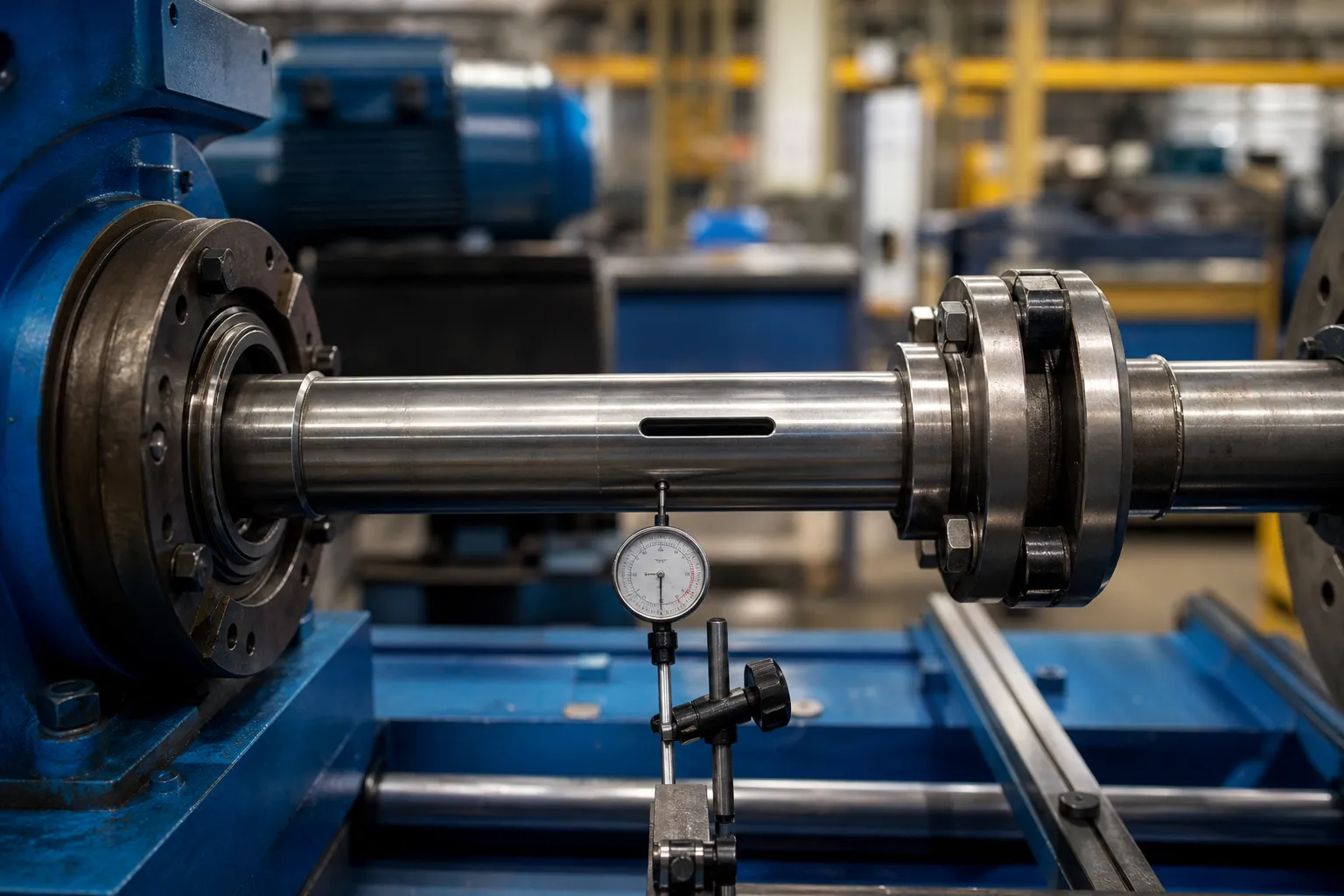
*Ilustracja koncepcja inżynierii. Stanowi wielofunkcyjne pytanie dotyczące pomiaru rotacyjnego, nie jest to zatwierdzone urządzenie lub wniosek, że obserwowany sygnał jest zakrzywiony.*
Oddzielenie błędu wrzeciona od błędu części
Na dowolnym instrumencie obrotowym, odczyt zawiera geometrię części plus błąd obrotu samego przyrządu – bicie wrzeciona, nośna wędrówka, wspierać ekscentryczność. Metrologia precyzyjna ma do tego standardowe techniki separacji, a ich logikę warto poznać nawet wtedy, gdy nie dysponuje się pełnym aparatem. Metody odwrotne mierzą część w jednej orientacji, następnie obróć część dokładnie o pół obrotu względem mocowania i zmierz ponownie: błąd części zachowuje współrzędne wpisania części, podczas gdy błąd konfiguracji zachowuje współrzędne maszyny wpisania, więc połączenie tych dwóch śladów oddziela je. Metody wieloetapowe rozszerzają tę samą ideę poprzez szereg indeksowanych orientacji. Na produkcyjnej maszynie do prostowania, praktyczni potomkowie są prostsi: ponowne osadzenie części w innej orientacji taktowania i sprawdzenie, czy ścieżka obraca się wraz z częścią, czy pozostaje nieruchoma w maszynie, mówi większość historii, a porównanie odczytów przed i po zamianie wspornika pozwala określić, który element do czego przyczynia się.
Te kontrole kosztują minuty i zapobiegają najdroższemu błędowi na tej stronie: korygowanie zakrętu, który żyje na ławce. Sprawiają również, że ostateczna korelacja ze wskaźnikiem klienta ma znaczenie, ponieważ obie strony tego porównania mierzą wówczas części, a nie konfiguracje – co stanowi podstawowe założenie miernik R&Badania R dotyczące linii prostujących.
Praktyczna sekwencja diagnostyczna
Powyższe kontrole składają się na ustaloną kolejność operacji, które należy wykonać przed podjęciem jakiejkolwiek decyzji korygującej. Pierwszy, oczyścić i sprawdzić elementy gniazd — środki, czasopisma, podpora bloków V — za uszkodzenia, zadziory i gruz, ponieważ najtańszym wyjaśnieniem jest zawsze konfiguracja. Drugi, weź ślad, ponownie osadź część w tej samej orientacji, i odtworzyć: niezgodność wykraczająca poza ustaloną powtarzalność konfiguracji wstrzymuje badanie urządzenia. Trzeci, ponownie osadzić w obróconej orientacji: ślad podążający za częścią jest sygnałem części; ten, który pozostaje nieruchomy w maszynie, jest sygnałem maszyny lub urządzenia. Czwarty, zamapuj co najmniej trzy stacje na całej długości i zanotuj, jak zachowuje się amplituda i faza składowej raz na obrót: różna amplituda i faza wirowania wskazują na zagięcie; stała faza z proporcjonalną amplitudą wskazuje na mimośrodowość. Piąty, spójrz na zawartość płatków w odniesieniu do historii obróbki części, zanim uwierzysz w jakiekolwiek wnioski. Dopiero wtedy wybierz reakcję – korekcję potwierdzonego wygięcia osi w zatwierdzonych strefach, lub alternatywne trasy dla wszystkiego innego, z leczonym stanem stanu uwolnionego pomiar załadowany i zwolniony.
Sekwencja istnieje, ponieważ każdy krok filtruje klasę fałszywych alarmów, które w przeciwnym razie przetrwałyby do następnego. Przeskoczenie do korekty polega na dociskaniu części w celu uzyskania osprzętu mimośrodowego, owalność i artefakty wciskania — uszkodzenia, których żaden późniejszy pomiar nie cofnie.
Wybierz odpowiedź z diagnozy
Jeśli dowody potwierdzają stan zgięcia osi i istnieją zatwierdzone strefy kontaktu/podparcia, kandydata na trasę prostowania można ocenić poprzez badanie próbki. Jeśli sygnał to głównie okrągłość, przerwana geometria, kwestia danych, błąd osprzętu lub osobna zależność między funkcjami, może być wymagany inny przegląd procesu lub inspekcji. Nie używaj prostowania w celu kompensacji problemów z pomiarem.
Do kontrolowanej korekcji lokalnej, Widzieć prostowanie punktowe. Dla korelacji z ostateczną metodą kontroli, zobacz korelację miernika maszyny z miernikiem klienta.
Sprawdź za pomocą miernika klienta
Przykładowy plan powinien zawierać znane/odniesienia warunki, jeśli są dostępne, powtórz konfigurację, wiele stacji, pomiar stanu uwolnionego, identyfikacja części i osprzętu, Zatrzymywanie surowych danych i korelacja wskaźników klienta. Wynik powinien określać, która cecha została oceniona i jakie niepewności lub ograniczenia konfiguracji pozostały.
Często zadawane pytania
Czy wysoki TIR zawsze oznacza wygięty wał??
NIE. TIR może zawierać dane, okrągłość, oprawa i inni współpracownicy. Najpierw zdiagnozuj konfigurację i wiele stacji.
Może wyprostować prawidłową okrągłość?
Nie jako ogólny wniosek. Okrągłość to inny warunek geometryczny i może wymagać innego procesu lub drogi kontroli.
Po co powtarzać konfigurację?
Ponowny odczyt po ponownym osadzeniu pomaga odróżnić sygnał przedmiotu obrabianego od podparcia, zmiana punktu odniesienia lub mocowania.
Co zwykle wskazuje ślad trójpłatkowy?
Najczęściej, powierzchnia uzyskana poprzez szlifowanie bezkłowe, gdzie trzypunktowy kontakt koła, koło regulacyjne i ostrze blokują sekcję w kształcie trzech płatków. Jest to kwestia formy przekrojowej, nie jest to kwestia osi, przed wybraniem jakiejkolwiek reakcji należy to sprawdzić w oparciu o historię obróbki części.
Jak odróżnić mimośrodowość od zgięcia za pomocą jednej sondy??
Przesuwaj sondę wzdłuż części i obserwuj składową raz na obrót. Zakręt pokazuje różną amplitudę i fazę przesunięcia pomiędzy stacjami; ekscentryczność utrzymuje wszędzie tę samą fazę i proporcjonalną amplitudę. Jeśli sonda nie może się poruszać, mapowanie kilku stacji z przesuniętą konfiguracją pozwala uzyskać taką samą separację kosztem ponownego umiejscowienia dyscypliny.
Czy ponowne osadzenie części w innej orientacji naprawdę powoduje oddzielenie błędu maszyny??
Tak, w najprostszej formie. Błąd części obraca się wraz z częścią; błąd maszyny i osprzętu pozostaje stały we współrzędnych maszyny. Porównanie śladów przy dwóch taktowaniach pokazuje, która klasa dominuje w czytaniu. Formalne metody odwrócenia i metody wieloetapowe udoskonalają tę samą zasadę w przypadku liczb, nie tylko klasyfikacja, są wymagane.