
Prostowanie punktowe jest kontrolowaną metodą korekcji miejscowej, nie wystarczy po prostu naciskać tam, gdzie część wygląda na wygiętą. Proces musi połączyć prawidłową mapę geometrii z zatwierdzonym punktem odniesienia, punkty wsparcia, ścieżka reakcji, dozwolone lokalizacje poprawek, kontrola przyrostowa i ponowny pomiar stanu zwolnionego. Bez tej pętli, skok prasy może pozostawić ślad, przesunąć sąsiedni obiekt lub zmniejszyć tymczasowy odczyt wskaźnika bez spełnienia rzeczywistych wymagań akceptacji.
To jest struktura procesu. Nie wymaga siły docisku StraighteningTech, udar, algorytm sterowania, zakres materiałów, dokładność, czas cyklu lub zgodność przedmiotu obrabianego. Wartości te wymagają przeglądu rysunku i zatwierdzonych próbek.
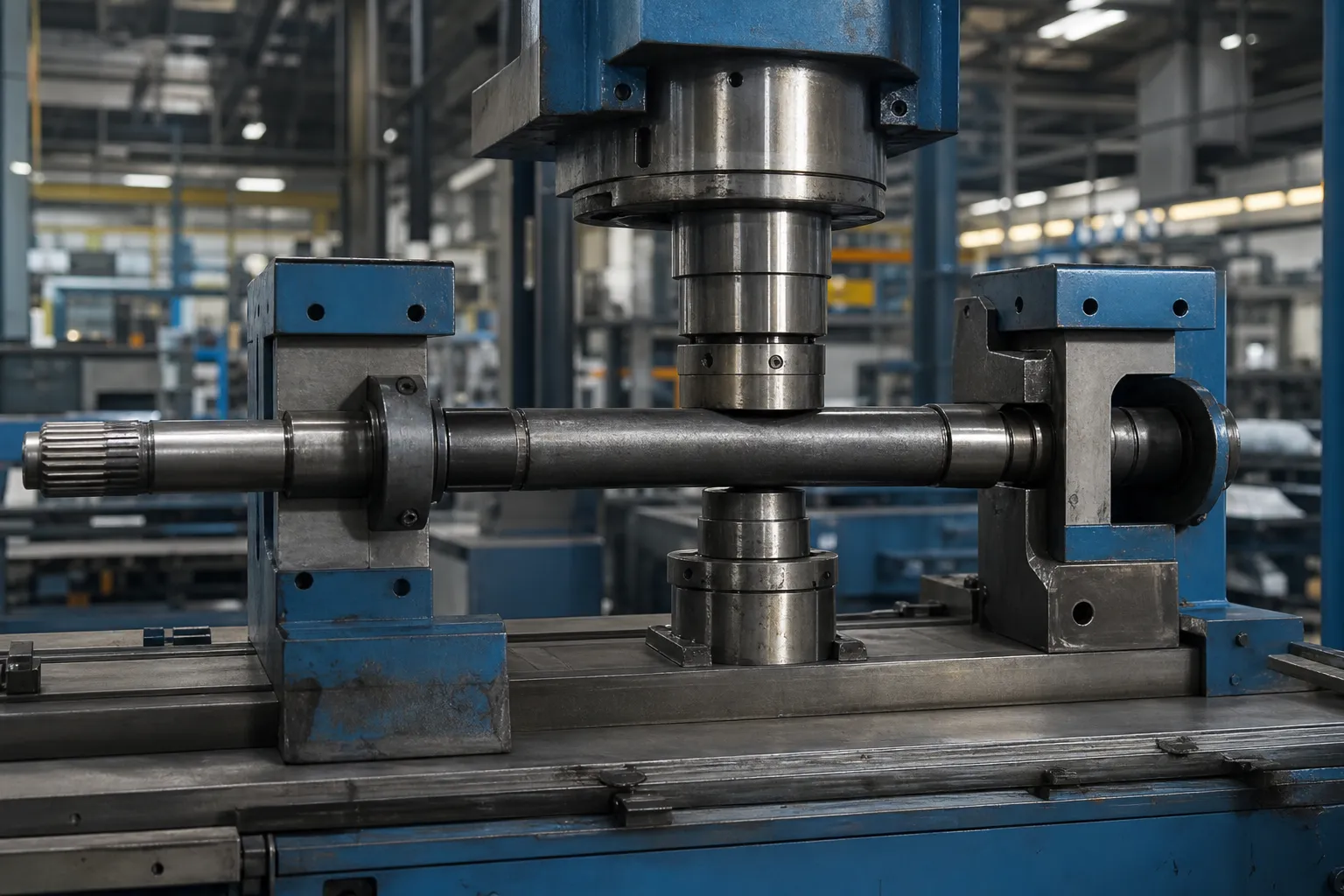
*Ilustracja koncepcja inżynierii. Pokazuje możliwy kontekst korekcji prasy dla konkretnej rodziny detali, nie jest to uniwersalna receptura procesu ani zweryfikowana lokalna wydajność.*
Zdefiniuj, co proces koryguje
Wymaganą cechą może być prostoliniowość na całej rozpiętości, bicie promieniowe względem osi odniesienia, przemiatanie boczne, lokalny związek cech lub inna kontrolowana geometria. Należy nadać jej nazwę przed wybraniem prasy. Błąd cykliczności, przerwanie powierzchni, sygnału urządzenia lub zamierzonego pochylenia nie można skorygować tak, jakby było to ten sam rodzaj zakrętu.
Używać prostość wału, bicie i TIR podczas kontroli rotacyjnej części. Rura, profil, wiosna, elementy pierścieniowe i spawane wymagają własnej geometrii i granic procesu.
Zbuduj początkową mapę błędów
Plan pomiarów powinien określać zatwierdzone dane, orientacja części, stacje osiowe, warunek wsparcia, metoda czujnika i kontrola powtórzeń/siedzenia. Pojedynczy odczyt punktu środkowego może pominąć wiele zagięć lub pomylić ugięcie grawitacyjne i zmienność mocowania z geometrią części.

*Ilustracja koncepcja inżynierii. Ilustruje mapę pomiarową przed korektą; rzeczywiste lokalizacje stacji, sondy i punkt odniesienia muszą być ustalone na podstawie kontrolowanego rysunku.*
| Wejście do zamrożenia | Decyzja, którą wspiera |
|---|---|
| Dane rysunkowe i reguła akceptacji | Ustala, co musi reprezentować pomiar |
| Wstępna mapa geometrii | Identyfikuje potencjalne strefy korekty i ryzyko interakcji |
| Atestowane podpory i punkty reakcji | Zapobiega tworzeniu się niezamierzonego sygnału na ścieżce siły |
| Chronione elementy i ograniczenia powierzchni | Określa, gdzie kontakt jest zabroniony |
| Etap materiału i procesu | Określa możliwą reakcję, ograniczenia sprężynowania i downstreamu |
Mechanika uderzenia punktowego
Korekcja punktowa to celowo wykonane trzypunktowe zgięcie. Dwie podpory i jeden punkt docisku tworzą ramę załadowczą: prasa popycha sekcję w kierunku podpór, moment zginający osiąga szczyt w punkcie docisku i opada w kierunku podpór, a zewnętrzne włókna w miejscu korekty przechodzą podatność, podczas gdy rdzeń sekcji pozostaje elastyczny. Kiedy siła zostanie uwolniona, elastyczny rdzeń próbuje sprężynować sekcję, podczas gdy powstałe włókna zachowują swój nowy kształt - różnica polega na trwałym zestawieniu, a sztuka tego procesu polega na zapewnieniu wystarczającej ilości pracy plastycznej, aby uwolniona część mieściła się w granicach tolerancji. Z tego obrazu wynikają bezpośrednio trzy konsekwencje. Korekta ma charakter lokalny: strefa plastyczna koncentruje się wokół punktu prasowania, dlatego mapy błędów wskazują, gdzie nacisnąć, a nie intuicja. Proces ten ustępuje samoistnie, jeśli jest leczony stopniowo: pojedynczego skoku o optymistycznym rozmiarze nie można cofnąć. I własna geometria przekroju – jego zmienność sztywności, jego przejścia, jego wcześniejsza historia deformacji – moduluje wszystko, dlatego też identyczne ustawienia skoku nie przenoszą się na ślepo pomiędzy średnicami, materiałów lub partii, i dlaczego efekty odwrotnego ładowania, zgodnie z opisem efekt Bauschingera, zmienić reakcję części, która została już raz poprawiona.
Rozpiętość wsparcia jest głównym parametrem dostrajania
Operatorzy sięgają po siłę wtedy, gdy powinni sięgać po geometrię. Przesunięcie podpór zmienia korektę przed dotknięciem jakiejkolwiek wartości siły: obsługuje szeroko rozłożone, daje długie, delikatne pole zginania — ta sama siła docisku powoduje większe ugięcie rozłożone na dłuższej strefie, odpowiedni dla pojedynczego szerokiego łuku; podpory blisko punktu korekcyjnego skupiają tę samą energię w zwarciu, głęboka korekta, odpowiednie dla miejscowego załamania, ale twardsze na powierzchni i przekroju. Rozpiętość określa również mechaniczną przewagę skoku: im bliżej podpór, tym większej siły wymaga ta sama korekta, dlatego zawężanie rozpiętości na sztywnym przekroju szybko osiąga granice maszyny lub części. Wypadają dwie praktyczne zasady. Pierwszy, wybierz rozpiętość z długości fali mapy błędów — długie łuki uzyskują duże rozpiętości, załamania stają się krótkie — i dokumentuj wybór w zapisie konfiguracji, ponieważ rozpiętość jest parametrem procesu jak każdy inny. Drugi, traktuj warunek podpory jako część oprzyrządowania: geometria kontaktu, czystość i zużycie cicho zmieniają ścieżkę reakcji, i dyscyplina narzędzi do ochrony powierzchni dotyczy podpór dokładnie tak samo, jak ma to miejsce w przypadku końcówki prasy.
Wybierz razem podpory i punkty korekcyjne
Punktu prasy nie można wybrać niezależnie od jego podpór. Rozstaw podpór, sztywność przekroju, kierunek siły i geometria kontaktu tworzą ścieżkę reakcji. Niewłaściwe wsparcie może sprawić, że lokalna prasa będzie wyglądać skutecznie, jednocześnie przenosząc błąd gdzie indziej lub uszkadzając funkcję.
Przed próbną próbą, dokument:
- miejsca wsparcia i reakcji, w tym strefy bezkontaktowe;
- punkt korekty, kierunek siły i dozwolona orientacja;
- materiał kontaktowy, kontrola czystości i ryzyka oznakowania;
- maksymalna korekcja przyrostowa i liczba prób;
- plan pomiarów sprężynowania/zwalniania;
- warunki twardego odrzucenia i przeglądu technicznego.
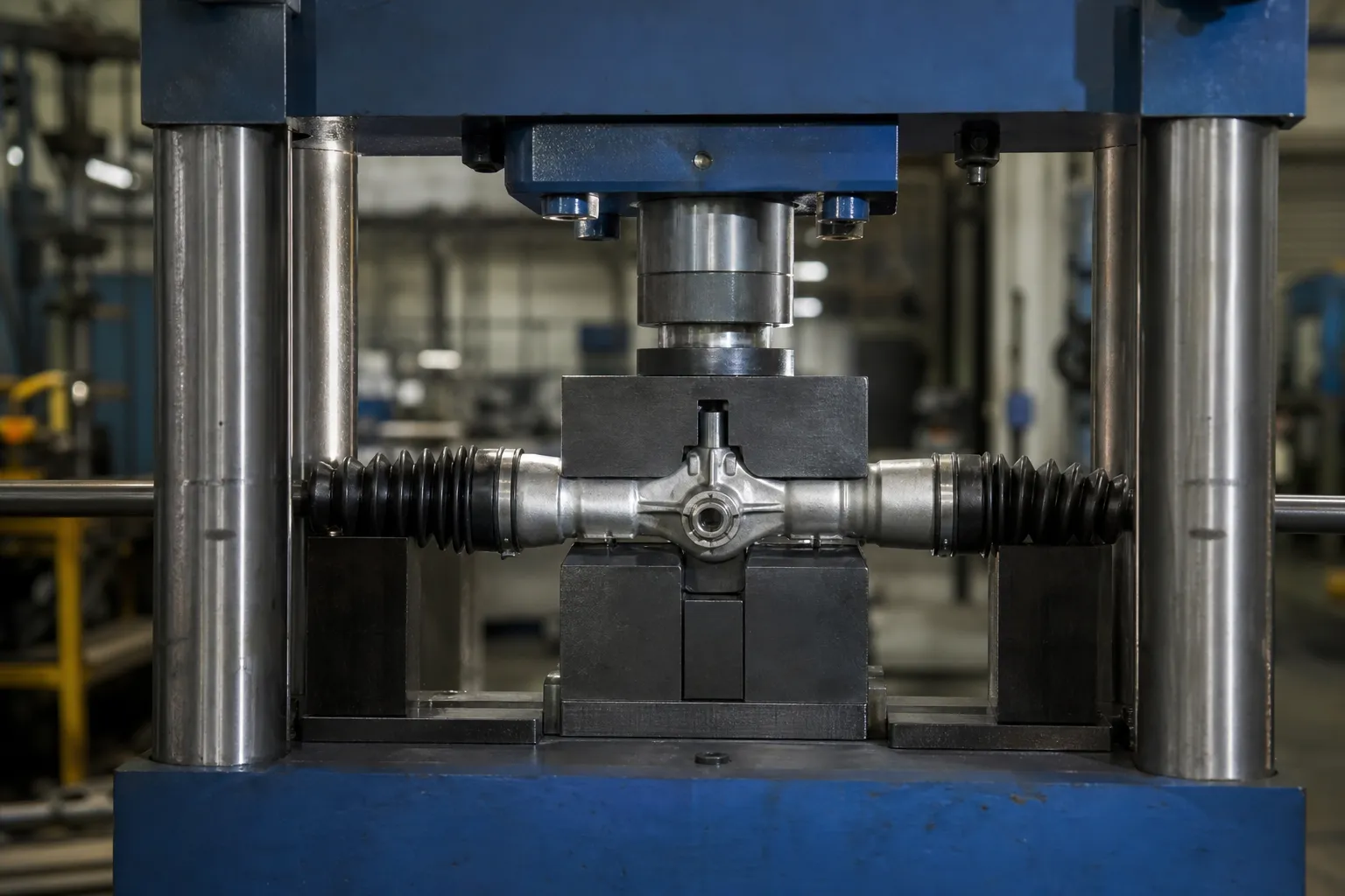
*Ilustracja koncepcja inżynierii. Przedstawia koncepcję korekcji przyrostowej; nie określa obciążenia prasy, udar, oprzyrządowanie lub zatwierdzony punkt korekty dla innego przedmiotu obrabianego.*
Poprawiaj stopniowo i sprawdź ponownie po wydaniu
Sekwencja w pętli zamkniętej to:
- zidentyfikować kontrolowaną rodzinę detali i wersję rysunku;
- sprawdzić pod kątem uszkodzeń, niewłaściwa część, zabroniony stan powierzchni lub deformacja poza zakresem;
- załaduj zatwierdzone dane i sprawdź osadzenie;
- zmierzyć początkową mapę geometrii;
- wybierz dozwolony plan wsparcia i napraw;
- zastosować korekcję przyrostową w granicach granicy próbka-test;
- całkowicie uwolnić siłę, zaciski i unieruchomienie;
- ponownie zmierz wszystkie wymagane ścieżki i zapisz wynik;
- skieruj część do OK, NOK lub przegląd techniczny.
Ostateczna akceptacja następuje po wydaniu. Odczyt, gdy część pozostaje pod wpływem siły docisku lub utwierdzenia uchwytu, nie może być wykorzystany jako dowód wyniku końcowego.
Springback jako zmienna procesowa, Nie stała
Ponieważ uwolniony kształt jest ustalany przez konkurencję między uzyskanymi włóknami a elastycznym rdzeniem, ten sam skok zapewnia różne trwałe ustawienie na częściach różniących się stanem materiału, sekcji lub wcześniejszej historii. To jest springback jako zmienna procesowa, a traktowanie go jako stałego współczynnika korygującego powoduje, że linie oscylują wokół tolerancji. Opisano dyscyplinę, która radzi sobie z tym uczciwie kompensacja sprężynowania przy prostowaniu wału: poznać odpowiedź na reprezentatywnych próbach, poprawiaj stopniowo, i naucz się ponownie, gdy zmieni się partia materiału lub rewizja części. Powiązana pułapka zasługuje na własne zdanie: celowe naciśnięcie części powyżej wartości nominalnej — przekroczenie w celu wstępnej kompensacji sprężynowania — jest uzasadnione w ramach zatwierdzonej receptury i określonego limitu, ale powtarzające się cykle przeregulowania i cofania kumulują uszkodzenia spowodowane ładowaniem wstecznym, a granica prób korekty istnieje właśnie po to, aby zatrzymać tę sekwencję, zanim stanie się ryzyko pęknięcia, za ramy oceny integralności.
Odczytywanie danych pomiędzy pociągnięciami
Każde pociągnięcie w pętli przyrostowej jest także eksperymentem, a dane pomiędzy pociągnięciami mówią operatorowi, kiedy kontynuować, a kiedy przestać. Zdrowa zbieżność pokazuje, że pozostały błąd zmniejsza się o wielkość z każdym skokiem — reakcja na skok spada w miarę zbliżania się części do celu, co jest naturalną oznaką stabilnej korekty. Trzy wzorce łamią tę sygnaturę i każdy wymaga zatrzymania się, a nie mocniejszego naciskania. Brak postępu: geometria przestaje odpowiadać, co oznacza, że proces nie powoduje już błędu – punktu korekty, stan podpory lub stan części uległ zmianie pod operatorem. Malejące zyski wraz ze wzrostem wysiłku: każdy skok powoduje mniejszy ruch części, podczas gdy prasa pracuje ciężej — sekcja walczy z umocnieniem przez zgniot, i kontynuowanie handlu zmniejszającego przyrost geometrii w celu gromadzenia szkód materialnych. Oscylacja: część przekracza wartość nominalną w naprzemiennych kierunkach skok po skoku — zasada korekcji działa przesadnie, często dlatego, że został skalibrowany na podstawie innej odpowiedzi, a rozwiązaniem jest przepis, nie ta część. Wbudowanie tych trzech wzorców zatrzymania w procedurę operacyjną przekształca dane między skokami z szumu w najwcześniejszy alarm jakości linii.
Dowiedz się, kiedy naciskanie punktu nie jest właściwą drogą
Prasowanie punktowe nie jest metodą domyślną dla każdego produktu. Drut ciągły, rura cienkościenna, profil asymetryczny, pierścień, wiosna, część o krytycznym znaczeniu zmęczeniowym lub wrażliwa na spawanie może wymagać innego podejścia, dedykowane narzędzia lub oddzielny przegląd procesu. Widzieć prasa kontra prostowanie wałkiem dla granicy wyboru metody.
Przykładowy test i akceptacja
Przykładowy plan powinien obejmować normalne i najgorsze przychodzące części, surowa przed/po geometrii, powtarzalność ponownego osadzania, kontrola powierzchni, wymagane kontrole materiałów/cech, limit maksymalnej próby i korelacja ze miernikiem referencyjnym klienta. Jeśli pęknięcia, twardość, Badania NDT, szlifowanie lub wyważanie są istotne, pozostają niezależnymi obowiązkami akceptacyjnymi.
Używać badanie próbki prostowania i akceptacja w celu zdefiniowania dowodów wymaganych przed złożeniem wniosku produkcyjnego lub decyzją FAT/SAT.
Często zadawane pytania
Czy punktowe naciśnięcie gwarantuje określoną dokładność?
NIE. Osiągalny wynik zależy od przedmiotu obrabianego, fakt, stan materialny, wsparcie, strefy kontaktu, odpowiedź na próbkę i uzgodnioną metodę inspekcji.
Czy najwyższy punkt wskaźnika jest zawsze punktem korekty??
NIE. Punkt korekcji należy wybrać z mapy geometrii i zatwierdzonej ścieżki reakcji, a nie z izolowanej obserwacji wizualnej lub wskaźnikowej.
Czy prasa może naprawić pęknięcie lub wymienić NDT?
NIE. Prostowanie nie naprawia wad materiałowych i nie zastępuje kwalifikowanych procesów kontrolnych.
Dlaczego ten sam skok prasy powoduje odmienne przesuwanie dwóch identycznie wyglądających części??
Ponieważ zwolniona geometria zależy od stanu materiału, szczegóły przekroju i wcześniejsze odkształcenie, nie na wygląd. Różne partie, stany obróbki cieplnej lub poprzedni cykl korekcyjny zmieniają równowagę plastyczną i elastyczną, na którą działa udar. Rozwiązaniem jest poznanie reakcji rodziny na próbkach i ponowne sprawdzenie jej w przypadku zmiany partii.
Kiedy podpory należy przybliżyć do siebie?
Gdy mapa błędów pokazuje krótki, lokalne załamanie, a nie szeroki łuk. Wąski zakres skupia korektę tam, gdzie występuje błąd; rozprzestrzenia go szeroka rozpiętość. Wybór zakresu należy do udokumentowanej konfiguracji, ponieważ zmienia zarówno kształt korekcji, jak i siłę, jaką musi wytrzymać część.
Co oznacza, gdy część przestaje reagować na poprawki?
Proces nie powoduje już błędu — jest to stan braku postępu. Przyczyny obejmują zmieniony punkt korekcji, zmianę ustawień lub zmianę stanu częściowego, a zdefiniowaną reakcją jest zatrzymanie i skierowanie części do przeglądu, nie zwiększać siły. Kontynuowanie naciskania powoduje marnowanie budżetu na odkształcenie części na nic.
Prostowanie przed i po szlifowaniu
Nie jest prowadzona żadna niezależna strona kanoniczna prostowanie przed vs po szlifowaniu ponieważ popyt dokładnie dopasowany do potrzeb przemysłu jest niewielki. Kolejność etapów, naddatek magazynowy i transfer danych należą do pręta kutego, strony procesu typu point-press i wielopunktowego. Przed zablokowaniem trasy produkcyjnej należy sprawdzić, czy szlifowanie usuwa materiał, który unieważniłby wcześniejszy odczyt prostoliniowości.
Krzywe przemieszczenia siły w prostowaniu
Dedykowana strona dla przewodnik po krzywej przemieszczenia siły prostującej nie jest obsługiwana bez potwierdzonego żądania zapytania. Interpretacja Troke’a Force’a, bezpieczne granice i warunki zatrzymania procesu są wyjaśnione w prasie punktowej, strony wielopunktowe i wykrywające pęknięcia. Każdy alarm oparty na krzywej musi zostać zweryfikowany na reprezentatywnych częściach, a nie skopiowany z innej rodziny materiałów.
Praca z naciskiem punktowym żyje lub umiera dzięki kontroli udaru – przeczytaj dlaczego nadmierna korekta powoduje pękanie części zanim zwymiarujesz maszynę, następnie użyj przewodnik po wyborze prostownicy aby dopasować koncepcje prasy do rodziny części.