
Didelės liejamos konstrukcijos dalys gali būti sudėtingos, plonasienė geometrija ir kelios funkcinės sąsajos. Patikima 3D tiesinimo sistema turi kontroliuoti atskaitos tašką ir tvirtinimo strategiją, matavimo būsena, kelių taškų korekcijos koncepcija, kontakto / paviršiaus rizika, įtrūkimų rizikos peržiūra ir išleista geometrija. Bendroji spauda arba paskelbta konkurentų architektūra nėra įrodymas, kad tiekėjas gali atlikti šį darbą.
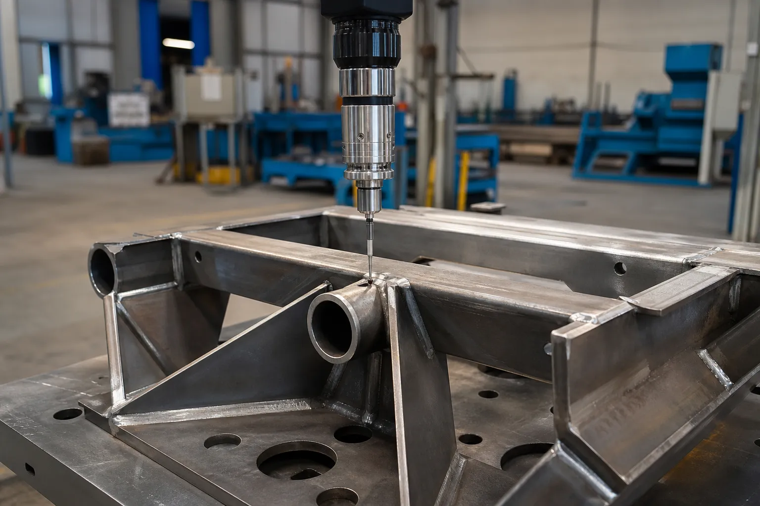
*Inžinerinės koncepcijos iliustracija. Tai neparodo patvirtintos taisymo sekos, Pavaros komplekto arba konstrukcijos dalies rezultatas.*
Nenurodykite jėgos, pavaros mechanizmų skaičius, ciklo laikas, tolerancija, įtrūkimų aptikimo greitis arba suderinamas liejimo tipas be projekto įrodymų. Šios vertės neperkeliamos iš popierinės ar konkurentų sistemos.
Why Large Castings Move After Casting
Cast structural parts distort because solidification and cooling are never uniform across a section of varying thickness. Thick features cool slowly and contract later than thin walls, so the casting leaves the die or mold with a locked-in residual stress field. That stress field is not visible on the part — it only announces itself later, when something changes. Ejection, trimming, terminis apdorojimas, shot blasting, and above all machining all remove or redistribute constraint, and the part moves toward a new equilibrium. A rear-structure casting that measured acceptable in the as-cast state can drift out of position tolerance after critical interfaces are machined, because removing material from one face releases the balancing stress on the opposite side.
This is why distortion control on structural castings is a sequence problem, not a single-press problem. The timing of the straightening operation inside the process route — before stress relief, po grubaus apdirbimo, before finish machining — changes both how much correction is needed and how stable that correction remains. Each of those routes has different risk: correcting an as-cast part may be undone by later machining, while correcting a finish-machined part risks damaging functional surfaces. The route decision belongs to the responsible process engineer, with the distortion history of the part in view.
What Makes Correction “3D” Instead of Planar
Conventional bar and shaft straightening corrects a centerline that is, to first order, a plane curve: bow in one plane, sometimes bow measured in two perpendicular planes and combined. The machine finds the high point of the bend, supports the part on two anvils, and presses at the peak. The geometry being controlled is a single neutral axis. This is the model behind kaip veikia automatinis veleno tiesinimas, and it assumes a stiff, uniform section.
A thin-wall structural casting breaks those assumptions. The section is not uniform — rails, šonkauliai, bosses and window openings give it direction-dependent stiffness, so the same applied force produces different deflection depending on where and in which direction it acts. The deviation is not one bend: it is a combination of bow in one axis, sweep in another, twist about the longitudinal axis, and local displacement of individual functional interfaces — a mounting pad seated high on one end, a bore axis tilted relative to the datum system. The measurand is the position and orientation of each functional interface in the part coordinate system, not a single runout reading. Any correction plan that only chases an overall bow will move interfaces it did not intend to move.
Practically, this means the error map for a structural casting is a table of interface deviations, not a polar diagram of a centerline. It also means correction targets must be prioritized: interfaces with tight position tolerances and mating consequences come first, and secondary geometry is allowed to float inside its own tolerance bands. That prioritization is a drawing-driven engineering decision made before any press stroke is planned.
Datum and Fixture Strategy Comes Before Correction
Measurement and correction of a casting are only as good as the datum system they reference. As-cast surfaces are draft angles and skin — they are neither repeatable nor representative. The part must be located on its drawing-defined machined datums, the same features the customer gauge will use at acceptance. If measurement uses one set of features and the customer gauge uses another, the two systems will disagree by setup error alone, before any real part variation enters. The principles are the same as those covered for pakopinio veleno matavimo atskaitos taško pasirinkimas, applied to a far less symmetric workpiece.
Fixtures for thin-wall castings carry an additional burden: the clamping and support scheme must not load the part into a false shape. A casting supported at the wrong points deflects under its own weight and under clamp force, and the measurement system will faithfully record that deflection as part error. Supports belong under stiff sections — ribs, rails, boss clusters — not in the middle of window openings. Every fixture concept should be proven by reseating: matuoti, unload, reload, measure again, and treat the spread between those readings as the floor of what the system can resolve. If reseating repeatability is poor, no amount of correction accuracy downstream will close the loop, a lesson that also drives Gagas R&R practice for straightening lines.
Correction Concepts and Their Limits
The mechanical idea behind correcting a casting is selective local plastic deformation: apply force at chosen points to shorten one side of the structure or shift its stiffness balance, so the released part settles closer to nominal. Two families of concepts exist. Point pressing — the same family described for tiesinimas taškiniu spaudimu — concentrates deformation at a support-and-press location and is best suited to localized deviations on stiff sections. Distributed or multi-point methods spread smaller corrections over several locations to reshape a longer span. Which concept fits a given casting depends on where the deviations sit and how the stiffness varies between them, which is exactly why a generic press specification answers nothing.
Three limits bound any correction route. Pirma, cast aluminum has limited ductility compared with drawn bar stock, and a thin-wall section concentrates strain: the crack-risk review — where cracks are likely, how they will be looked for, and who accepts the result — must be settled before the first trial stroke, not after a suspect part appears. Antra, correction interacts with the residual stress field that caused the distortion. A correction imposed without regard to that field can relax during subsequent handling, machining or thermal exposure; stress behavior after correction is a topic treated separately for tiesinimas po terminio apdorojimo. Trečia, over-correction on a casting is usually not recoverable by pressing back, because reverse loading accumulates low-cycle fatigue damage in the section.
The discipline that manages all three limits is the same incremental loop used on precision shafts: small correction, paleisti, išmatuoti iš naujo, decide. The measure–correct–release–remeasure cycle described for long structural sections such as elevator guide rails scales down to castings in principle, but with one added rule: because interface positions rather than a single centerline are the target, each loop must re-read the interface table, not just the worst single reading.
Matavimas, Turi būti suderintas vientisumas ir atleidimas
Kūrimo įrašas turėtų išsaugoti gaunamą geometriją, atskaitos taško / armatūros nustatymas, matavimo metodas/duomenų versija, korekcijos seka, išleista geometrija, paviršiaus/apžiūros radiniai ir išdėstymas. Jei reikia patikrinti vientisumą, jo metodas, apimtį ir priėmimo įgaliojimus turi nurodyti atsakingos inžinierių ir kokybės komandos.
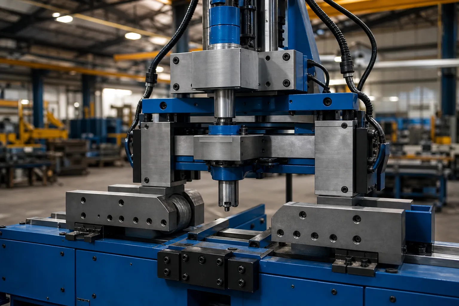
*Inžinerinės koncepcijos iliustracija. Tai nėra turimos įrangos įrodymas, saugos dizainas arba giga liejimo programa.*
Žr armatūros pakartojamumas ir atskaitos taškas ir matavimo neapibrėžtis tiesumo tikrinimo metu atitinkamiems valdikliams; nė vienas nepateikia 3D liejimo galimybių įrodymų.
Prieš pateikiant bet kokią tiekėjo pretenziją reikalingi įrodymai
OPEN paskelbimo sprendimui reikalingas realus autorizuotas liejimo projektas, brėžinyje apibrėžtas 3D atskaitos taškas ir tvirtinimas, matavimo prieš / po / išleidimo duomenys, taisymo įrašai, paviršiaus / vientisumo peržiūra, priimti pavyzdžiai ir kliento leidimas. Iki tol šis puslapis yra tyrimų sistema. Dėl išsamios inžinerinės diskusijos, susisiekite su StraighteningTech su įgaliota projekto informacija.
Būtinas patvirtinimas prieš pateikiant paraišką dėl sistemos
Any system claim for giga-cast correction needs a defined workpiece scope, calibrated datums and fixtures, atsekami matavimo duomenys, and correlation with the customer’s own gauge. Bendra įrenginio galimybė nėra patvirtintas šios temos rezultatas.
DUK
Can a giga-cast structural part be straightened on a bar straightening machine?
Not as a drop-in. Bar straightening machines assume a uniform stiff section and a single centerline error. A thin-wall structural casting has direction-dependent stiffness, twist and interface-position deviations, and needs a datum, fixture and measurement concept built around its drawing — plus a crack-risk review appropriate to cast ductility. Some underlying correction physics is shared; the workholding, measurement and validation are not.
Should stress relief come before or after straightening a casting?
That depends on the distortion history and the process route, and it is a decision for the responsible process engineer. Correcting before stress relief risks later relaxation of the correction; correcting after removes one instability source but may face harder material. What should be non-negotiable is that the choice is deliberate, documented, and consistent between the trial and production.
What evidence should a buyer request before accepting a 3D straightening proposal?
A drawing-defined 3D datum and fixture concept, measurement data in the as-received and released states, the correction record for every trial part, an integrity or crack-inspection scope agreed with the quality team, and acceptance judged on the customer gauge. A proposal that offers only machine specifications, without those items, is not a proposal for this work.
Susiję tiesinimo technologijos ištekliai
Žr kaip veikia automatinis veleno tiesinimas, tiesinimo pavyzdžio bandymas ir priėmimas ir veleno tiesumas vs išbėgimas vs TIR bendroms valdymo riboms, kurios taikomos prieš bet kokį pajėgumų reikalavimą 3D Giga-Cast konstrukcinių dalių tiesinimas.

*Inžinerinės koncepcijos iliustracija.*
Giga-casting correction is an automation-first conversation – į rankinis ir automatinis palyginimas addresses the process jump, ir ROI dėklas automatiniam tiesinimui addresses the capital question.