
Alkūninis velenas yra daugelio ašių nuovargiui svarbus komponentas, ne įprastas apvalus velenas. Jo pagrindiniai guolių kakliukai turi nustatyti bendrą sukimosi ašį, o kiekvienas švaistiklio alkūninis kaištis sąmoningai seka poslinkį orbitą. Tinklalapiai, atsvarus, stumdomi veidai, filė spinduliai, alyvos skylės, nosies ypatybės ir smagračio flanšas turi įtakos matavimui ir saugiam apkrovos keliui.
Todėl prieš pasirenkant mašiną patikimas alkūninio veleno tiesinimo sprendimas turi atsakyti į penkis klausimus:
- Ar tai gamybos alkūninis velenas, atnaujinama dalis arba mažo variklio remontas?
- Kuri pagrindinė žurnalo ašis ir atramos sąlygos apibrėžia posūkio žemėlapį?
- Ar nuokrypis yra koreguojamas visuotinis posūkis, vietinio žurnalo formos klaida, šlifavimo medžiagos problema arba įtrūkimų/pažeidimų būklė?
- Kuris slėgis, medžiagoje ir proceso stadijoje patvirtintas ritinėlių tiesinimo arba šukavimo kelias?
- Kaip bus išleista geometrija, filė vientisumas, turi būti patikrintas šlifavimo kiekis ir galutinis balansas?
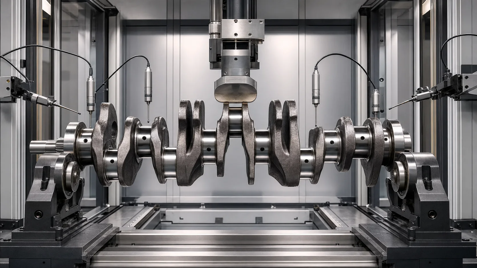
*Inžinerinės koncepcijos iliustracija: kelių metimų alkūninis velenas palaikomas ir išmatuotas kontroliuojamos korekcijos tyrimui. Tai nėra kliento svetainės nuotrauka. Faktinės kontaktinės zonos, jėgos ribos ir mašinos architektūra reikalauja brėžinių ir reprezentatyvių pavyzdžių bandymų.*
Alkūninio veleno tiesinimas nėra viena rinka
DataForSEO rezultatai pagal crankshaft straightening machine tame pačiame rezultatų puslapyje rodyti kelis skirtingus paieškos tikslus: mažų variklių remonto įrankiai, dirbtuvių hidrauliniai presai, didelė alkūninio veleno remonto įranga ir aukštos produkcijos gilaus valcavimo/ritinio tiesinimo sistemos. Jie neturėtų būti sujungti į vieną bendrą mašinos pasiūlymą.
| Alkūninio veleno šeima | Tipiškas kontekstas | Inžinerinis maršrutas |
|---|---|---|
| Kaltas automobilių alkūninis velenas | Kontroliuojama gamyba tarp apdirbimo operacijų | Automatinis matavimas ir patvirtintas slėgio arba ritinėlio tiesinimo procesas |
| Didelis dyzelinas, jūrinis arba pramoninis alkūninis velenas | Nauja gamyba arba specializuotas remontas | Sunkus valdymas, kelios atramos ir konkrečiam projektui pritaikytas slėgio / riedėjimo maršrutas |
| Atnaujinamas alkūninis velenas | Nešioti, karštis, avarijos ar guolio gedimo istorija | Apžiūra, šlifavimo ir remonto sprendimas prieš tiesinimą |
| Mažas vertikalaus veleno variklio švaistiklis | Kompaktiškų remonto įrankių rinka | Atskiras produktas, tvirtinimo ir saugos vokas |
| Sumontuotas arba presuotas alkūninis velenas | Keli surinkti tinkleliai, kaiščiai ir trukdžiai tinka | Surinkimo derinimo procesas; ne vientisas kaltinio švaistiklio receptas |
| Ketaus arba mazginis alkūninis velenas | Konkrečiai medžiagai būdingas nuovargis ir įtrūkimų elgsena | Metalurgijos patvirtinimo ir ribotos korekcijos tyrimas |
Šiame puslapyje dėmesys sutelkiamas į vientisus pramoninius ir automobilių alkūninius velenus. Mažam vejos įrangos tiesintuvui ar pastatytam motociklo alkūniniam velenui reikia kitokio sprendimo.
Apibrėžkite alkūninio veleno anatomiją ir pradinę grandinę
Techniniame pasiūlyme turėtų būti nurodyta kiekviena funkcinė savybė:
- visi pagrindiniai guolių kakliukai ir jų numeracija;
- švaistiklio alkūniniai kaiščiai, insultas ir kampinė fazė;
- juostos ir atsvarai;
- priekinė nosis, laiko nustatymas, raktų griovelis, spline arba pavaros ypatybės;
- galinis flanšas, bandomosios angos ir smagračio sąsaja;
- traukos paviršiai ir ašinis atskaitos taškas;
- pagrindinis- ir pin-žurnalo filė spinduliai;
- alyvos skylės, kryžminiai gręžimai ir vidiniai praėjimai;
- grūdintos arba giliai valcuotos sritys;
- balanso skylės, frezuotos trinkelės arba papildomos balansavimo funkcijos;
- centrai arba laikini proceso atskaitos taškai;
- šlifavimo medžiaga pagal žurnalą ir proceso etapą.
Pagrindinio žurnalo bendroji ašis paprastai valdo visuotinį lenkimo sprendimą. Smeigtukai yra sąmoningai ekscentriški ir turi būti įvertinti pagrindinės ašies atžvilgiu, insultas ir fazė. Neapdorotas švaistiklio radialinis judėjimas nėra tiesioginis sulenkto veleno įrodymas.
Užšaldykite gamybos arba remonto etapą
Po kalimo ir grubaus apdirbimo
Dalyje gali būti nuosėdų, atsargų kitimas ir nebaigtos atskaitos ypatybės. Korekcija gali palaikyti paskesnį apdirbimą, tačiau matavimo sistema turi skirti atsargų kitimą nuo tikrojo ašies poslinkio.
Po Main- ir Pin-Journal išankstinis apdirbimas
Galimi funkciniai žurnalo takeliai ir proceso atskaitos taškai, kol lieka šlifavimo atsargos. Hegenscheidtas aprašo gilų valcavimą ir ritininį tiesinimą po išankstinio apdirbimo, su pagrindinio guolio TIR išmatuota prieš pataisos skaičiavimą. Tai patvirtina, kad proceso etapas ir atsargų planas yra neatsiejami.
Po terminio apdorojimo arba paviršiaus sukietėjimo
Liekamasis stresas, kietumas ir spyruokliškumas gali keistis. Jėgos / poslinkio receptas iš minkšto ruošinio negali būti automatiškai perkeltas į grūdintą alkūninį veleną. Įtrūkimų rizika ir patikrinimas po proceso tampa aiškiais priėmimo vartais.
Po filė gilaus kočiojimo
Gilus valcavimas naudojamas liekamajam gniuždymo įtempiui sukelti labai apkrautose filėse. Vėlesnė koregavimo operacija neturi sunaikinti numatytos filė būklės arba nustatyti nepatvirtintą deformacijos kelią. Slėgio kontaktas ant filė yra draudžiamas, nebent alkūninio veleno dizaineris patvirtintų specialų procesą.
Prieš galutinį šlifavimą
Ištiesinimas gali sumažinti atsargų kiekį, reikalingą bendrai pagrindinio žurnalo ašiai sukurti. Išeinantis žemėlapis turi įrodyti, kad kiekviename žurnale vis dar yra pakankamai šlifavimo.
Po galutinio šlifavimo
Žurnalo skersmuo, apvalumas, paviršiaus apdaila, filė geometrija ir traukos paviršiai yra funkcionalūs. Ryšys tampa labiau ribojantis, ir pakartotinio šlifavimo / taisymo / atmetimo būdas gali būti saugesnis nei tolesnis slėgio koregavimas.
Aptarnavimas arba perdirbimo grąžinimas
Šilumos žala, guolio priepuolis, taškais, įtrūkimai, ankstesnis šlifavimas, suvirinimas, padengimas arba išankstinis tiesinimas gali pakeisti riziką. Prieš taikant jėgą, reikalinga remonto istorija ir apžiūros įrašas.
| Scena | Pagrindinė Galimybė | Pagrindinė rizika | Reikalingi įrodymai |
|---|---|---|---|
| Grubus kalimas | Sumažinkite apdirbimo disbalansą | Atsargų kitimas užmaskuoja geometriją | Kvalifikuoti proceso atskaitos taškai ir atsargų žemėlapis |
| Iš anksto apdirbtas | Galimas kelių žurnalų posūkių žemėlapis | Neteisinga palaikymo nuoroda | Pagrindinio žurnalo TIR ir šlifavimo pašalpa |
| Termiškai apdorotas | Teisingas terminio apdorojimo iškraipymas | Atsparumas ir įtrūkimo pradžia | Medžiagos / kietumo ir jėgos poslinkio bandymai |
| Giliai valcuotas | Koordinuokite nutekėjimo ir filė stiprumo procesą | Gniuždomosios filė būklės pažeidimas | Proceso savininko patvirtinimas ir filė apsauga |
| Apdaila – gruntas | Gelbėjimas pagal galutinę geometriją | Paviršiaus / formos pažeidimai ir prarastos atsargos | Visas žurnalo / filė patikros ir remonto limitas |
| Paslaugos grąžinimas | Atkurkite remontuojamą komponentą | Paslėptas nuovargis, karščio arba prieš pataisytą žalą | NDT, istorija, atsargų ir disponavimo taisyklės |
Atskirkite pagrindinius žurnalus nuo ofsetinių alkūninių smeigtukų
„Marposs“ aprašo alkūninio veleno matuoklį, kuris matuoja ir pagrindinio kaklo skersmenis, besisukančius apie pagrindinę geometrinę ašį, ir kaiščio kaklo skersmenis, skriejančius aplink tą ašį.. Tai yra esminis signalo atskyrimo reikalavimas.
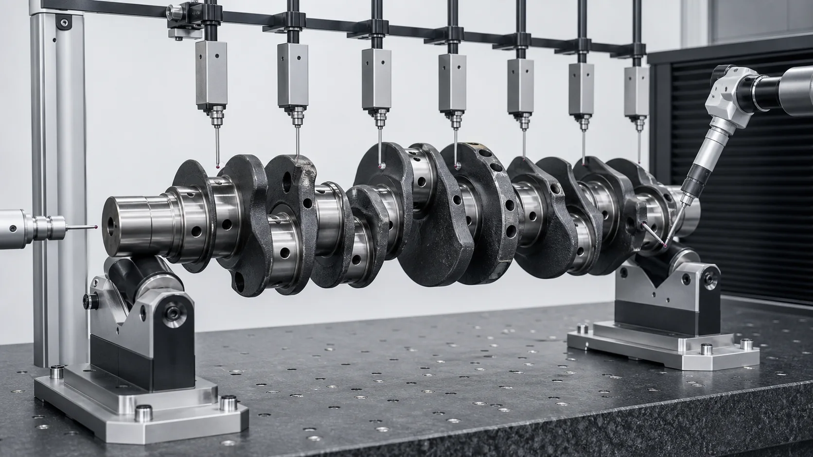
*Inžinerinės koncepcijos iliustracija: pagrindinio žurnalo posūkių žemėlapiui ir poslinkio alkūninio kaiščio geometrijai reikalingi atskiri matavimo takeliai. Tikrosios zondo vietos, sukimosi modelis ir funkcijų kaukės atitinka brėžinį ir matuoklio koreliacijos planą.*
| Matavimo takelis | Ką ji nustato | Dažna klaida, jei naudojama netinkamai |
|---|---|---|
| Visi pagrindiniai žurnalai | Bendrosios ašies bėgimo ir posūkio žemėlapis | Vietinis skilimas interpretuojamas kaip visuotinis posūkis |
| Priekiniai ir galiniai pagrindiniai žurnalai | Atraminė / atskaitos ašis | Pabaigos žala iškreipia visą žemėlapį |
| Smeigtukai | Skersmuo, orbita, smūgio ir fazės ryšys | Tyčinis ekscentriškumas aiškinamas kaip išsiveržimas |
| Stūmimo veidai | Ašinė vieta ir veido išbėgimas | Skaitant dominuoja įbrėžimai arba vietinis nusidėvėjimas |
| Priekinė nosis ir galinis flanšas | Susietųjų komponentų ryšys | Funkcijos klaida traktuojama kaip veleno lenkimas |
| Žurnalo apvalumas/cilindriškumas | Vietinė forma | Maža TIR reikšmė slepia vietinę formos klaidą |
| Filė ir alyvos skylių regionai | Konstrukcinė ir paviršiaus būklė | Praleistas nuovargiui svarbus defektas |
| Pusiausvyros koregavimo plokštumos | Masės ašies būklė | Pusiausvyra painiojama su geometriniu tiesumu |
Nidec alkūninio veleno matavimo sistema atskirai įvertina kakliuko ir kaiščio išorinį skersmenį. „Marposs“ taip pat palaiko galutinį arba tarpoperacinį matmenį, geometrinis ir neardomasis matavimas. Perkeliama pamoka nėra konkurento tikslumo vertė; tai brėžiniu pagrįsto kelių charakteristikų tikrinimo plano poreikis.
Pasirinkite teisingą palaikymo nuorodą
Galima išmatuoti alkūninio veleno nutekėjimą:
- tarp kvalifikuotų centrų;
- pagrindinių žurnalų pabaigoje;
- ant pasirinktų V formos ritinėlių;
- guoliams lygiavertėse atramose;
- šlifavimo staklėje arba specialioje matuoklio sąrankoje.
Hegenscheidtas išvardija išsiveržimo matavimus, susijusius su centrais arba V blokais. Šios sąrankos automatiškai neduoda identiškų rezultatų. Sprendimas turėtų apibrėžti:
- fizinės paramos žurnalai ir koordinatės;
- centro būklė ir kvalifikacijos metodas;
- žurnalo apvalumo kompensacija;
- ašinis suvaržymas ir leistinas judėjimas;
- švaistiklio kampas ir kampinis indeksavimas;
- didelių alkūninių velenų gravitacinis nuosmukis;
- jutiklio jėgos ir funkcijų kaukės;
- išleistos būsenos pakartojamumas;
- koreliacija su malūnėliu ir kliento matuokliu.
Mašina neturi keisti atskaitos taškų korekcijos kilpos viduryje be nustatyto transformacijos ir koreliacijos tyrimo.
Slėgis, Ritinio tiesinimas ir lupimas yra skirtingi procesai
Kontroliuojamo slėgio tiesinimas
Spauda taiko lokalizuotą trijų taškų arba suvaržytą apkrovą patvirtintame pagrindinio žurnalo regione. Sunkioji Gleason remonto įranga demonstruoja vieną rinkos kelią, kuriame palaikomos, Viršutiniai laikikliai ir kilnojamasis cilindras lokalizuoja darbą aplink pasirinktą žurnalą. Tikslus konkurento išdėstymas ir talpa nėra StraighteningTech specifikacija.
Reikalingas slėginis tiesinimas:
- patikrinta visuotinio posūkio diagnozė;
- patvirtintas įkėlimo kelias per žurnalus / žiniatinklius;
- plataus spindulio kontaktiniai įrankiai;
- jėgos ir poslinkio lubos;
- atspirties charakteristika;
- pilnas iškrovimas prieš priėmimą;
- įtrūkimų ir paviršiaus patikra po korekcijos.
Ritinio tiesinimas
Hegenscheidt derina nuo kampo priklausomą gilų valcavimą, pagrindinio guolio TIR matavimas ir ritininis tiesinimas. Tai gamybos technologija, susijusi su filė apdorojimu ir pirminio šlifavimo geometrija. Jo nereikėtų apibūdinti kaip bendrą kelių ritininių strypų tiesintuvą.
Peening
Remonto rinkos SERP taip pat rodo valymo būdus. Šveitimas keičia vietinį liekamąjį įtempimą ir reikalauja atskiro kvalifikuoto darbo instruktažo, operatoriaus valdikliai, paviršiaus taisyklės ir patikrinimas. Tai nėra automatinis slėgio tiesinimo pakaitalas, ir šis straipsnis nepretenduoja į universalų šveitimo receptą.
| Metodas | Potencialus tinka | Pirminis valdymas | Nemanykite |
|---|---|---|---|
| Slėgio tiesinimas | Patvirtintas plikas alkūninis velenas su saugiu apkrovos keliu | Force, poslinkis, atramos tarpas ir išleistas TIR | Gatavos filė/žurnalai toleruoja kontaktą |
| Ritininis tiesinimas | Gamybos procesas integruotas su žurnalo/fillavimo operacijomis | Nuo kampo priklausomas riedėjimo ir pagrindinio žurnalo žemėlapis | Tie patys įrankiai tinka kiekvienai švaistiklio šeimai |
| Peening | Specializuotas remonto metodas | Vieta, intensyvumo, liekamasis įtempis ir paviršiaus patikrinimas | Kalimas iš prigimties yra saugus arba kartojamas |
| Šlifavimas | Vietinė forma / skersmuo ir ribotas ekscentriškumas sandėlyje | Žurnalo geometrija ir atsargų šalinimas | Šlifavimas gali pašalinti kiekvieną visuotinį posūkį |
| Keitimas/atmetimas | Plyšys, deginti, nepakankamas atsargų kiekis arba nesaugus krovinio kelias | Inžinerinis nusiteikimas | Kiekvienas sulenktas alkūninis velenas yra remontuojamas |
Sukurkite apsaugotą kontaktų žemėlapį
Numatytosios nespaudžiamos ir nepalaikomos zonos
- pagrindinis- ir pin-žurnalo filė spinduliai;
- alyvos skylės ir kryžminiai gręžimai;
- kompensuoti alkūninius kaiščius, nebent juos patvirtintų specialus maršrutas;
- stūmimo paviršiai ir baigti flanšo paviršiai;
- raktų grioveliai, splines, gijos ir laiko funkcijos;
- balanso angos ir vietinės masės korekcijos funkcijos;
- aštrūs juostos perėjimai ir ploni atsvaro kraštai;
- giliai valcuoti, indukciniu būdu grūdintas, azotuotas, suvirinti, padengtos arba suremontuotos sritys;
- įtrūkęs, sudegė, įbrėžtus arba karščio paveiktus paviršius;
- baigti žurnalai be apsaugoto įrankių patvirtinimo.
Potencialiai patvirtintos zonos
- neapdorotos arba pusiau gatavos pagrindinio žurnalo žemės su pakankamomis atsargomis;
- apdirbti antkaklius ar aukojamuosius pratęsimus;
- dizainerio patvirtinti žiniatinklio / žurnalo įkėlimo keliai;
- specialios riedėjimo kontaktų vietos, nustatytos gamybos procese.
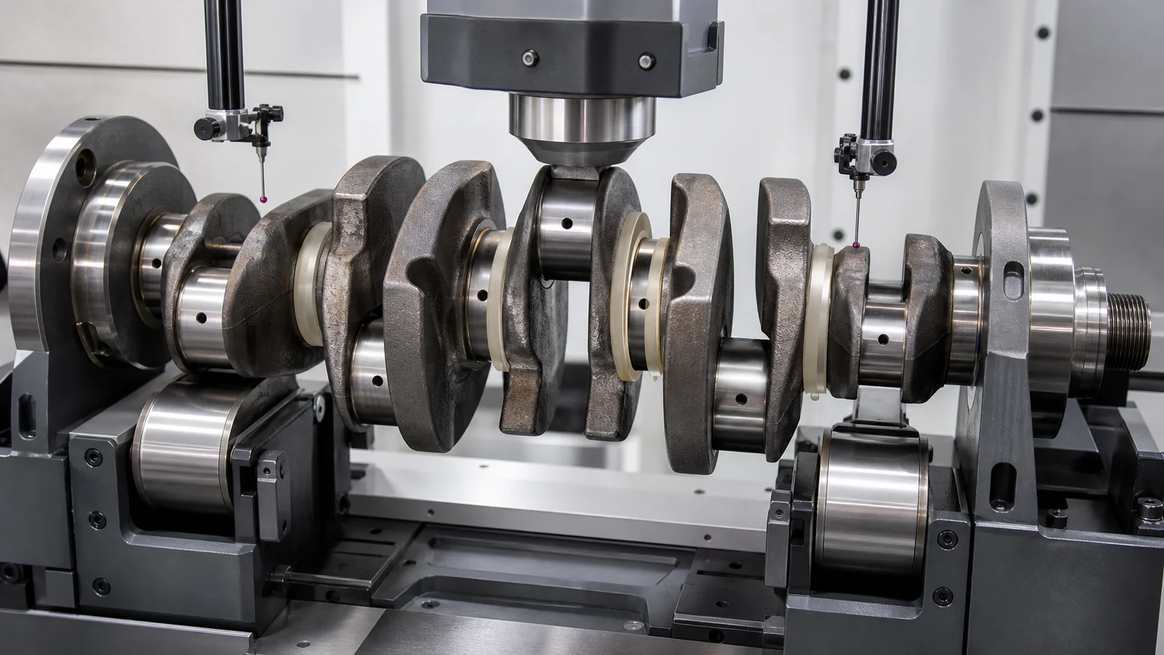
*Inžinerinės koncepcijos iliustracija: pataisymas apsiriboja patvirtintu pagrindinio žurnalo apkrovos keliu, o filė, alyvos skylės, alkūniniai smeigtukai ir traukos paviršiai lieka apsaugoti. Vaizdas neleidžia naudoti šių vietų tikrajai daliai.*
Saugaus kontakto žemėlapis turėtų būti saugomas pagal dalies numerį ir brėžinio peržiūrą. Saugus kakliukas prieš šlifavimą vėliau gali tapti apsaugotu galutiniu paviršiumi.
Valdykite atgalinį ir kryžminį sujungimą
Vieno pagrindinio kakliuko korekcija pakeičia gretimų juostų ir kakliukų elastinę formą. Procesas turėtų naudoti visą pagrindinio žurnalo posūkio žemėlapį, o ne siekti vienos indikatoriaus smailės.
Kiekvienam korekcijos žingsniui:
- pasukti ir išmatuoti visus valdomus pagrindinius žurnalus;
- atskirti vietinę formą nuo centro poslinkio;
- nustatyti korekcijos koordinates ir švaistiklio kampą;
- taikyti patvirtintą laipsnišką apkrovą;
- įrašyti jėgą ir poslinkį;
- pilnai iškrauti;
- pasukite ir iš naujo išmatuokite visą žemėlapį;
- patikrinkite gretimus alkūninius kaiščius, trauka / flanšas ir apsaugoti paviršiai;
- sustabdyti nenormalų standumą, nepasikartojimo arba patikrinimo požymis.
Pakrautas poslinkis nėra galutinis rezultatas. Tik išleistas ir pakartotas žemėlapis gali nustatyti, ar atsvara buvo kompensuota saugiai.
Tiesinimas prieš šlifavimą
Šlifuojant gali susidaryti kakliuko skersmuo, apvalumas, cilindriškumas ir paviršiaus apdaila. Jis taip pat gali pašalinti ribotą ekscentriškumą, kol lieka atsargų. Negalima daryti prielaidos, kad bus atkurta bendra pagrindinė žurnalo ašis, jei reikalingas atsargų pašalinimas pažeistų dydį, filė ar kietumo ribos.
Sprendimui priimti reikia kiekvieno žurnalo atsargų žemėlapio:
- įeinantis skersmuo ir išbėgimas;
- minimalus galutinis dydis;
- likęs kietas sluoksnis arba remonto danga;
- leistina mažo dydžio/remonto klasė;
- filė ir traukos paviršiaus geometrija;
- šlifuoklio atrama ir atskaitos taško nustatymas;
- numatoma atsarga po išleisto tiesinimo.
„Marposs“ šlifavimo matuokliai rodo, kad pagrindinio ir kaiščio kakliuko skersmuo turi skirtingus judėjimo ir matavimo reikalavimus. Todėl tiesinimas ir šlifavimas turėtų būti suplanuoti kaip sujungtos, bet atskiros operacijos.
Tiesinimas vs balansavimas
Alkūninio veleno balansavimas koreguoja masės pasiskirstymą, palyginti su apibrėžtomis korekcijos plokštumomis ir, varikliuose, gali būti susietas su svoriu ir besisukančiomis / abipusio judėjimo masės prielaidomis. Tai nepataiso pagrindinio žurnalo koaksialumo, smeigtuko žurnalo forma arba sulenkta pasaulinė ašis.
Jei tiesinimas, šlifavimas, gręžimas, frezavimas, suvirinimas, dengimas arba medžiagos pašalinimas įvyksta po balansavimo, galutinė balanso sąlyga turi būti patikrinta dar kartą. Alkūninis velenas gali praeiti geometriškai ir vis tiek neatitikti balanso reikalavimo, arba išlaikyti pusiausvyrą, kai pagrindinis žurnalas yra geometriškai pasislinkęs.
Plyšys, Paviršiaus ir nuovargiui jautrus patikrinimas
Pasiekti nutekėjimo tikslą nepakanka, jei pataisymas sukelia žalingą požymį arba pažeidžia nuovargį lemiantį paviršių. Patikrinimo plane turėtų būti nurodyta:
- išankstinis valymas ir vizualinis patikrinimas;
- magnetinė dalelė, sūkurinės srovės arba kitas patvirtintas NDT kelias pagal medžiagą/procesą;
- filė ir alyvos angos uždengimas;
- žurnalo įdubimas, sumušimų ir paviršiaus apdailos ribos;
- šlifavimo-degimo arba karščio pažeidimų patikrinimas;
- kietumo / gylio patikrinimai, kai reikia;
- išankstinio suvirinimo priėmimo kriterijai, dengimas arba remontas;
- patikrinimo laikas prieš ir po korekcijos/šlifavimo;
- inžinerinis nusiteikimas ribinėms indikacijoms.
Hegenscheidt proceso teiginys dėl nuovargio ir stiprumo išsaugojimo priklauso jo patvirtintai valcavimo sistemai. Jo negalima perkelti į slėgio ištiesinimo pasiūlymą be mūsų pačių mėginių, medžiagos patvirtinimas ir nuovargiui jautrus patvirtinimas.
Uždarojo ciklo alkūninio veleno tiesinimo procesas
1. Nurodykite dalį
Įkelkite teisingą receptą iš alkūninio veleno numerio, variklių šeima, medžiaga, proceso stadija, brėžinio taisymo ir remonto istorija.
2. Apžiūrėkite ir išvalykite
Nuvalykite žurnalus ir atskaitos paviršius. Patikrinkite alyvos angas, filė, žurnalų paviršiai, tinklai, nosis ir flanšas. Užbaikite reikiamą išankstinį NDT.
3. Kvalifikuokite „Datum“ sąranką
Patikrinkite centrus arba palaikymo žurnalus, ašinė vieta, sukimosi ir sėdėjimo pakartojamumas.
4. Sukurkite kelių žurnalų žemėlapį
Išmatuokite kiekvieną pagrindinį žurnalą sukdami. Įrašų žurnalas, stūmimas, nosies ir flanšo charakteristikos atskirai, jei reikia.
5. Klasifikuokite nuokrypį
Atskirkite visuotinį posūkį nuo kakliuko skilties, smailėjantis, šlifavimo medžiagos klaida, švaistiklio fazės / eigos klaida, flanšo pažeidimas, įtrūkimas, šilumos iškraipymas arba disbalansas.
6. Pasirinkite patvirtintą metodą ir įkėlimo kelią
Pasirinkite slėgį, riedantis, peening, šlifavimas arba atmetimas pagal patvirtintą dalies maršrutą. Patvirtinkite visas saugomas zonas.
7. Taikykite laipsnišką korekciją
Valdymo jėga, poslinkis, švaistiklio kampas ir įrankių padėtis. Sustabdykite nenormalią reakciją.
8. Atleiskite ir išmatuokite iš naujo
Visiškai iškraukite ir vėl pasukite alkūninį veleną. Atnaujinkite visą pagrindinio žurnalo žemėlapį, o ne tikrinkite tik pataisytą vietą.
9. Apžiūrėkite ir nukreipkite pasroviui
Atlikite NDT / paviršiaus patikras po korekcijos ir patvirtinkite šlifavimo medžiagą. Maršrutas į šlifavimą, galutinis matavimas, balansavimo ir surinkimo patikra.
10. Įrašykite rezultatą
Parduotuvės tapatybė, recepto peržiūra, atskaitos taško nustatymas, prieš/po žemėlapius, pataisos koordinates, jėgos ir poslinkio kreivės, signalizacijos, apžiūra ir disponavimas.
Siūlomas alkūninio veleno tiesinimo elementas
Konkrečiam projektui skirta sistema gali apimti:
- elektromechaninis arba hidraulinis koregavimo įrenginys, kurio dydis nustatomas bandant mėginį;
- reguliuojami pagrindinio žurnalo ritinėliai, centrai arba V formos atramos;
- servo sukimosi ir švaistiklio kampo indeksavimas;
- keli išsikrovimo jutikliai pagrindinio žurnalo žemėlapiui;
- atskiras alkūninis kaištis, stūmimas, nosies ir flanšo matavimo moduliai;
- platūs keičiami presavimo batai ir apsaugotos atramos;
- automatinė filė laikymo logika, alyvos skylės ir atsvarai;
- jėgos / poslinkio stebėjimas ir spyruoklės kompensavimas;
- sunkiųjų dalių pakrovimas, kėlimo ir apsisukimo sauga;
- recepto kontrolė, atsekamumas ir kokybės duomenų eksportas;
- sąsajos su šlifavimu, NDT ir balansavimo įrašai.
Mažo automobilių alkūninio veleno konfigūracija automatiškai netinka dideliam laiviniam alkūniniam velenui arba remonto dirbtuvių daliai.
Bandymo ir priėmimo plano pavyzdys
Reprezentatyvūs pavyzdžiai turėtų apimti:
- mažiausias ir didžiausias alkūninio veleno ilgis, sūpynės, masė ir kakliuko skersmuo;
- skirtingų pagrindinių žurnalų skaičius, alkūninio smeigtuko smūgiai ir atsvarų išdėstymai;
- suklastotas, išlietos ir patvirtintos remonto sąlygos;
- grubus, iš anksto apdirbtas, termiškai apdorotas, giliai valcuoti ir baigti šlifuoti etapai;
- medžiagos ir kietumo kraštutinumai;
- numatomos įeinančios lenkimo formos ir švaistiklio kampai;
- žurnalo formos klaidų pavyzdžiai, kurie neturėtų sukelti taisymo;
- minimali šlifavimo medžiaga;
- patvirtintos ir draudžiamos kontaktinės zonos;
- jėga / poslinkis ir atgalinis apvalkalas;
- gretimų žurnalų kryžminė jungtis;
- pagrindinio žurnalo ir švaistiklio matuoklio koreliacija;
- Prieš/po NDT ir paviršiaus rezultatai;
- galutinis šlifavimo ir balanso patikrinimas;
- pakartojamumas ir NOK maršrutas.
Naudokite Ištiesinimo pavyzdžio bandymo ir priėmimo vadovas atskirti pagrįstumą, RIEBALAI, SAT ir gamybos galimybės.
Duomenys, reikalingi techniniam pasiūlymui
Pateikite:
- alkūninio veleno braižymas ir peržiūra;
- variklis / taikymas ir alkūninio veleno šeima;
- vientisa kaltinė/lietinė arba pastatyta konstrukcija;
- medžiaga, terminis apdorojimas, kietumas ir filė apdorojimas;
- dabartinis gamybos ar remonto etapas;
- pagrindinis-žurnalas, alkūninis kaištis, stūmimas, nosies ir flanšo matmenys;
- insultas, kaiščio fazės ir atsvaros išdėstymas;
- naftos gręžinių ir vidinių pravažiavimų žemėlapis;
- gaunamo pagrindinio žurnalo vykdymo žemėlapis pagal kampą;
- žurnalo apvalumas, cilindriškumas ir kūgiškumas;
- braižymo atskaitos taškai ir kliento matavimų nustatymas;
- patvirtintos atramos/koregavimo zonos ir draudžiami objektai;
- šlifavimo medžiaga pagal žurnalą;
- įtrūkimas, deginti, paviršiaus ir remonto priėmimo kriterijai;
- šlifavimas pasroviui, balansavimo ir surinkimo seka;
- ataskaitos ir atsekamumo reikalavimai;
- reprezentatyvūs mėginiai tyrimams.
Dažnai užduodami klausimai
Ar galima ištiesinti alkūninį veleną?
Kai kuriuos alkūninius velenus galima pataisyti, bet įgyvendinamumas priklauso nuo medžiagos, statyba, proceso stadija, lenkimo forma, šlifavimo žaliava, filė būklė ir saugus apkrovos kelias. Plyšys, dėl karščio pažeisto žurnalo arba nepakankamai atsargų gali reikėti taisyti arba atmesti.
Kaip sužinoti, ar sulenktas alkūninis velenas?
Išmatuokite visus pagrindinius kakliukus naudodami kvalifikuotą atramą ir atskirkite vietinį apvalumą nuo centro poslinkio. Alkūninio smeigtuko orbitinis judėjimas, traukos paviršiaus išbėgimui ir flanšo / nosies funkcijoms reikia atskirų takelių.
Ar galite paspausti alkūnę ar filė?
Nemanykite, kad taip. Smeigtukai yra kompensuojami, o filė yra labai svarbi nuovargiui. Numatytasis kontaktų žemėlapis apsaugo alkūninius kaiščius, filė, alyvos angas ir užbaigtus traukos paviršius, nebent būtų patvirtintas specialus procesas.
Ar šveitimas yra geresnis nei tiesinimas presu?
Tai skirtingi liekamojo streso ir korekcijos procesai. Teisingas maršrutas priklauso nuo alkūninio veleno konstrukcijos, medžiaga, gamybos/remonto etapas ir patvirtintos darbo instrukcijos. Nė vienas neturėtų būti pasirinktas iš bendros interneto procedūros.
Ar šlifavimas gali pašalinti alkūninio veleno lenkimą?
Šlifavimas gali pašalinti ribotą ekscentriškumą atsargų ribose ir sukurti galutinę žurnalo formą. Jis negali saugiai išspręsti visų bendrosios ašies klaidų. Naudokite kiekvieno žurnalo atsargų žemėlapį.
Ar vis dar reikalingas alkūninio veleno balansavimas?
Taip, kai nurodyta. Tiesinimas koreguoja geometriją; balansavimas koreguoja masės pasiskirstymą. Dar kartą patikrinkite balansą po bet kokios operacijos, kuri keičia geometriją ar masę.
Ar reikia patikrinti, ar techninės priežiūros alkūninis velenas nėra įtrūkęs?
Taip, pagal medžiagą, remonto standartas ir kliento reikalavimas. Plyšiui paslėpti negalima naudoti tiesinimo, deginti, priepuolis arba ankstesnė taisymo būklė.
Sukurkite sprendimą aplink pagrindinės žurnalo ašį
Kuriame alkūninio veleno tiesinimo sprendimus pagal tikrąją švaistiklio šeimą, pagrindinio žurnalo data, poslinkio alkūninio kaiščio geometrija, proceso stadija, apsaugotos filė, saugus apkrovos kelias, išleistas lenkimo žemėlapis, šlifavimo medžiaga ir galutinė patikrinimo seka. Mašinos architektūra paremta įrodymais iš brėžinių ir pavyzdinių bandymų, o ne pagal bendrą veleno receptą ar konkurento specifikaciją.
Next steps for a crankshaft project: confirm the machine concept with the velenas, vamzdžių ir profilių tiesintuvo pasirinkimo vadovas, then frame the business case with the tiesinimo mašinos sąnaudų struktūra.
Nusiųskite alkūninio veleno brėžinį, proceso stadija, materialinė būklė, gaunamo žurnalo žemėlapis, šlifavimo pašalpa, patikrinimo standartas ir tipiniai pavyzdžiai. Tada galime apibrėžti matavimo strategiją, slėgio arba riedėjimo maršrutas, įrankių žemėlapis, Jūsų alkūninio veleno pritaikymo korekcijos vokas ir atsekamas priėmimo planas.
Susiję: Skirstomojo veleno tiesinimas vyksta pagal tą pačią atskaitos logiką – žr skirstomojo veleno tiesinimo tirpalas.