
A drill collar is not a pipe with thick walls — it is a heavy, near-solid tubular machined from a single bar of quenched-and-tempered steel, placed at the lowest section of the bottom hole assembly (BHA) to put weight on the bit and provide stiffness. Because there is essentially no thin wall to distribute strain, straightening a bent drill collar is a high-force, crack-sensitive correction problem, closer to press-straightening a large forged bar than to leveling drill pipe or production tubing.
Any drill collar straightening solution has to answer five questions before a machine or process is selected:
- Is the collar an OEM new-manufacturing part, or an in-service joint entering an inspection-and-repair loop?
- What is the outside diameter, total length and wall configuration — slick, spiral-grooved or non-magnetic?
- Where is the bend: mid-body sag from handling, a local dogleg near a connection, or distributed fatigue-related curvature?
- How much correction force does the cross-section actually require, and where are the no-press zones (threads, spiral grooves, slip recesses)?
- How will straightness be verified after correction and after stress relaxation — straightedge, taut wire, or rotating runout measurement?
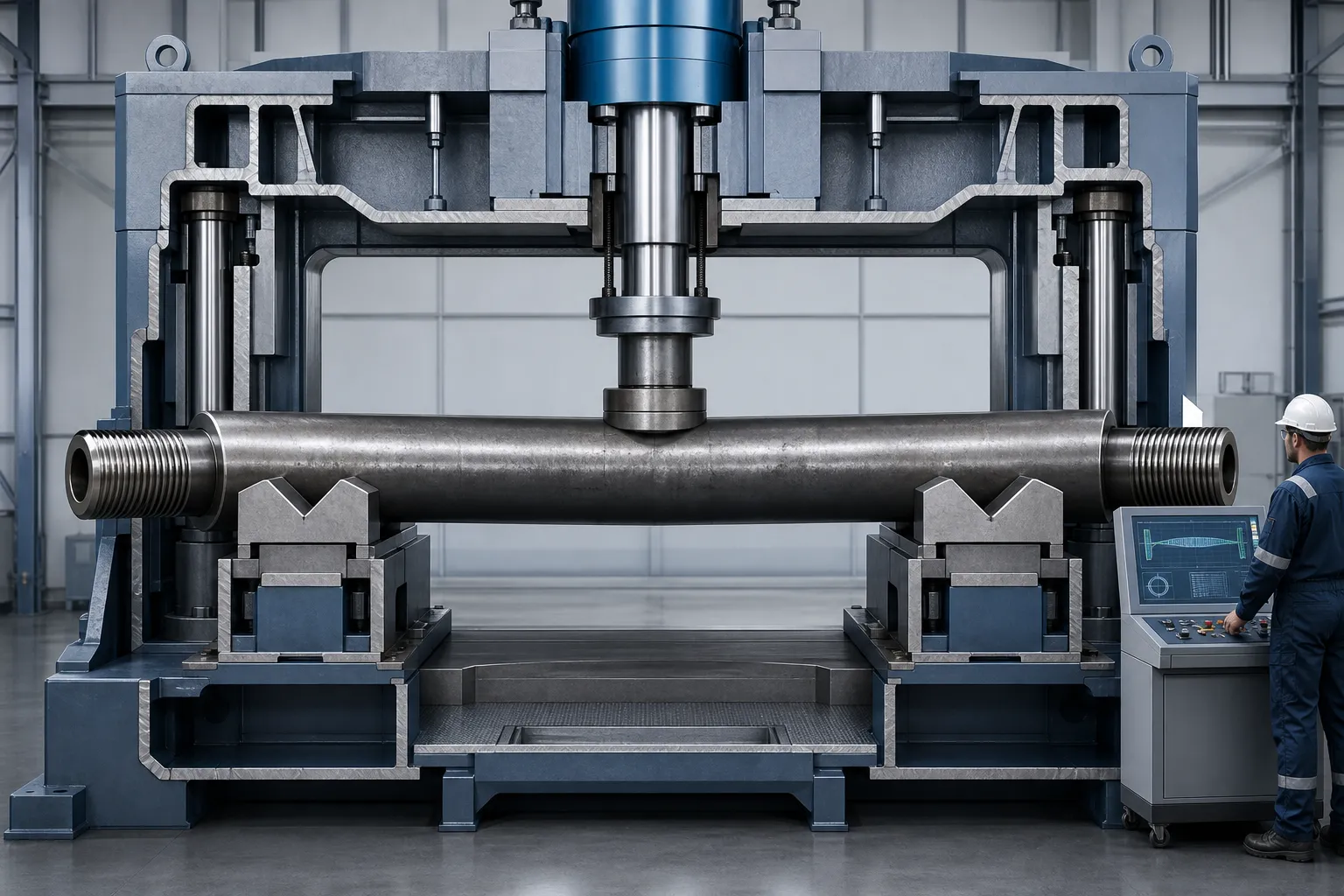
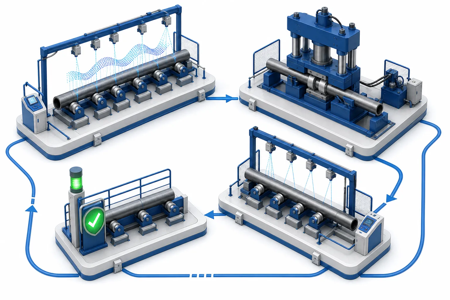
*Engineering concept illustration: a heavy-wall drill collar supported and corrected in a press-straightening study. It is not a customer-site photograph. Force values, support spacing and acceptance limits require sample-part verification against the applicable standard edition.*
Where Drill Collars Sit Among Oilfield Tubulars
Search results for drill collar straightening mix real oilfield content with noise (machinery directories, even garment-care pages), but the serious results cluster around two audiences: OEM manufacturers such as NOV producing integral heavy-wall collars from solid bar stock, and inspection/service companies such as Holly Pipe that straighten drill pipe, heavy weight drill pipe and drill collars during inspection. Both are legitimate equipment buyers — with very different duty cycles. Before either conversation starts, the workpiece family must be placed correctly:
| Component | Role in the String | Cross-Section | Straightening Character |
|---|---|---|---|
| Drill pipe | Main string body above the BHA; transmits rotation and mud | Thin-wall tube with friction-welded tool joints (API 5DP territory) | Moderate force; body flexibility gives useful springback margin |
| Heavy weight drill pipe (HWDP) | Transition zone between flexible pipe and stiff collars | Thick-wall tube with center upset / wear pad | High force with upset-zone avoidance; see our HWDP straightening page |
| Drill collar | Bottom of the BHA; supplies bit weight and stiffness | Heavy wall machined from solid bar (typically AISI 4145H mod., reported in manufacturer literature) | Highest force per size; crack-sensitive; press-cycle with strict protection zones |
| Non-magnetic collar | MWD/LWD compass isolation in directional assemblies | Stainless-family solid bar (reported: manganese-chromium and nickel-copper grades) | Different work-hardening and galling behavior; separate process study |
| Tubing & casing | Production conduit after drilling | Relatively thin wall | Lower force, ovality-sensitive; covered in our oil tubing and casing straightening article |
If you arrived here for the string-body component, start from our oil drill pipe straightening overview; for the sucker-rod side of artificial lift, see sucker rod straightening. This article stays with the collars themselves.
Why Collar Bends Happen and What They Cost
Published care-and-handling guidance for drill collars concentrates on exactly the events that create bends: lifting without adequate support span, setting slips unevenly, and shock loads while tripping. In service, the lowest collars see alternating bending stress each revolution; a collar that leaves the string with curvature keeps accumulating localized stress in the same zones, which is why inspection contractors routinely put straightening ahead of cleaning and inspection in their reconditioning sequence — the geometry must be known good before wall-thickness and crack surveys mean anything.
The commercial driver is straightforward: a bent collar is a scrapped asset only if nobody can restore it. Inspection-shop straightening converts written-off joints back into rental inventory, and OEM shops need an in-line correction step after heat treatment and machining. Both sides reject parts for the same reason — curvature beyond the acceptance limit of the applicable specification, or runout at the connections that will misalign the BHA downhole.
Measurement Datum Before Correction
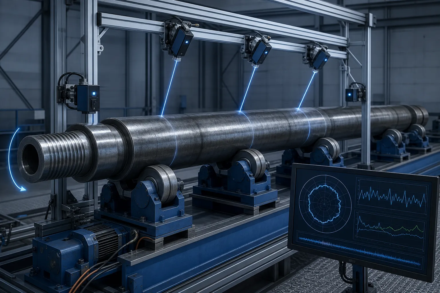
Classical drill-pipe practice verifies straightness with a straightedge or taut string/wire — a method drill-collar shops still use for quick screening. For collar-grade acceptance and for machine control, rotating measurement is more informative: support the joint near its ends on aligned rollers or V-blocks, rotate it, and map radial runout along the length. This separates true centerline bend from ovality and surface lobing, a distinction we treat in detail in shaft straightness vs runout vs TIR.
Two datum decisions matter specifically for collars. First, measure on the body, not across the threaded connections — connection runout is an assembly-coaxiality question that body pressing may not fix. Second, record the rotational clock position of the high point at several stations; a single-station dial check cannot tell a global bow from a local dogleg, and the press strategy differs completely between the two. Multipoint layouts for this class of mapping are discussed in LVDT multipoint shaft measurement.
Process Route: Press, Not Roll
Rotary straightening machines (angled-roll machines) economically calibrate long thin-wall tube and bar in continuous passes. A drill collar’s near-solid section resists that route: the rolling load would be enormous and the surface under the rolls is often a finished, gauged body or a spiral groove that must not be work-flattened. The oilfield standard route is therefore gag-press straightening — support the joint at two stations, back the high point toward a pressure ram, and press in controlled increments. Field-service contractors describe portable hydraulic gag presses doing exactly this on tubing, drill pipe, HWDP and drill collars in the 2-3/8″ to 6-5/8″ and larger ranges (reported equipment descriptions from BD Oilfield, LeadNDT and similar service providers).
Press-straightening physics and its springback behavior are covered in press straightening vs roller straightening and springback compensation. The collar-specific delta is scale: reported press capacities in oilfield pipe-straightening applications reach the 60-ton machine class, because the section modulus of a solid-body collar is an order of magnitude above the string pipe it hangs beneath. Any machine proposition for this family should be validated on representative sample joints with the real connection hardware in place.
Deviation Classes and Where Correction Is Allowed
| Deviation Class | Typical Origin | Correction Posture |
|---|---|---|
| Global body bow | Handling and lifting stress, storage on insufficient supports | Multi-station press program, small increments, re-measure between cycles |
| Local dogleg near connection | Slips, shoulder strikes, make-up torque events | Short-span pressing with thread protection; verify connection runout afterwards |
| Distributed service curvature | Rotating bending fatigue in deviated holes | Cautious limited correction; engineering review of remaining life before any press |
| Bend with visible cracking or gouges | Impact damage, stress corrosion | Not a straightening case — route to NDT and disposition first |
| Ovality or lobing without centerline bend | Slip crushing, wall collapse tendency | Not correctable by bending; form error must be measured, not pressed |
Protection zones are stricter than on any other tubular in this series: never press on the threaded connections or their shoulders, never place supports inside slip recesses, and on spiral-grooved collars keep ram and support contact on the full-diameter lands between grooves. Spiral grooves exist to reduce differential sticking wall contact — a flattened or burred land changes both the flow path and the stress distribution, and it cannot be restored by later machining without removing stock from the gauged body.
Non-Magnetic Collars: Material Discipline Beyond Geometry
Non-magnetic drill collars carry the MWD/LWD survey instruments of a directional assembly, which means their straightness matters twice: once for the same BHA dynamics as any collar, and once because a bowed collar changes the clearance and vibration environment around the instrument string itself. Rental and inspection companies make the linkage explicit — one collar rental specialist describes its collars as precision-balanced and straightened specifically to reduce vibration (reported service description) — which is the instrument-protection argument stated in commercial form.
The materials are a different world from 4145H carbon steel: non-magnetic collars are produced from stainless families, with manganese-chromium and nickel-copper grades the ones reported in manufacturer literature. For straightening, two behavior differences lead the risk list. These alloys work-harden noticeably under repeated local loading, and they are galling-sensitive — so support and ram materials, surface finishes and cleanliness standards must be chosen against marking and metal pickup, not just against force. A pressure foot that is harmless on carbon steel can leave work-hardened pickup marks on an austenitic body, and those marks sit exactly where handling and slip contact will find them later.
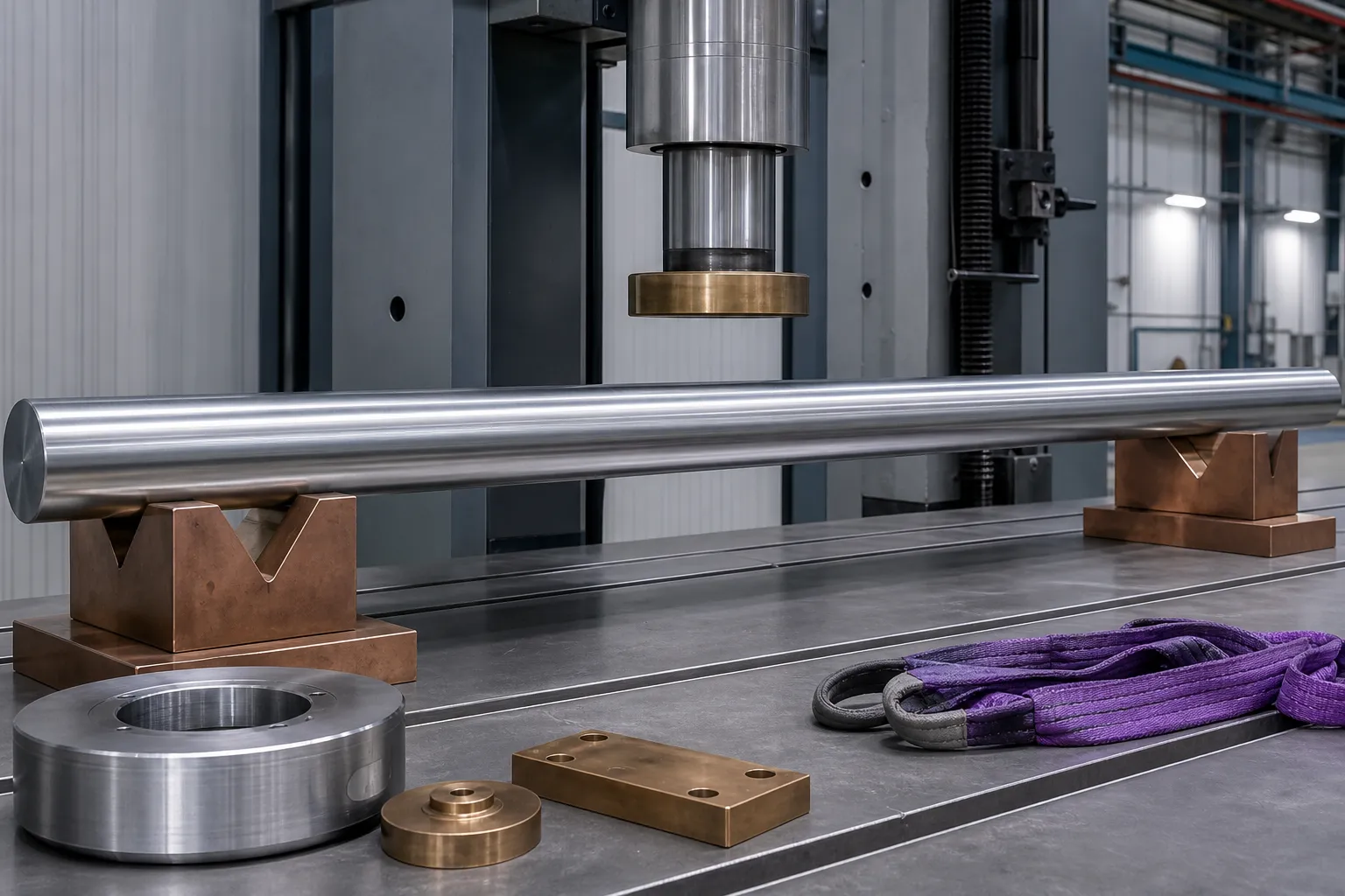
The discipline unique to this family is magnetic cleanliness. The entire point of the collar is to keep ferromagnetic influence away from magnetometer-based surveys; the straightening cell must not undo that. Steel chains, magnetic chucks, plain iron support blocks and wire-rope slings are all contamination and magnetization sources — wire swarf pressed into a support face, or a magnetized fixture contact, can leave the collar locally magnetized or carrying embedded ferrous debris that later corrupts survey data. Cells that handle non-magnetic collars work with non-magnetic tooling (stainless or copper-alloy supports and pads) and textile slings, and they keep an end-of-line magnetization check with demagnetization available — demagnetization already appears as a standard step in published oilfield tubular and rod reconditioning flows (reported service listings), and the same logic transfers to this family.
Measurement follows the same rule: magnetic instrument bases clamped to the collar body are a contradiction on this workpiece, so sensor mounts are non-magnetic and the multipoint layout is built from standalone stations — the general layout logic in LVDT multipoint shaft measurement applies unchanged. Damage disposition is stricter too: any press mark, gouge or crack indication on a non-magnetic collar goes to materials engineering review before rework is attempted, because repair options for these grades are narrower than for quenched-and-tempered carbon steel. If your mix includes both collar families, treat them as separate process studies that share a press frame — and for the downhole-motor side of the same instrument environment, see our mud motor rotor straightening page.
Spiral-Grooved Collars: Press on the Lands, Never in the Grooves
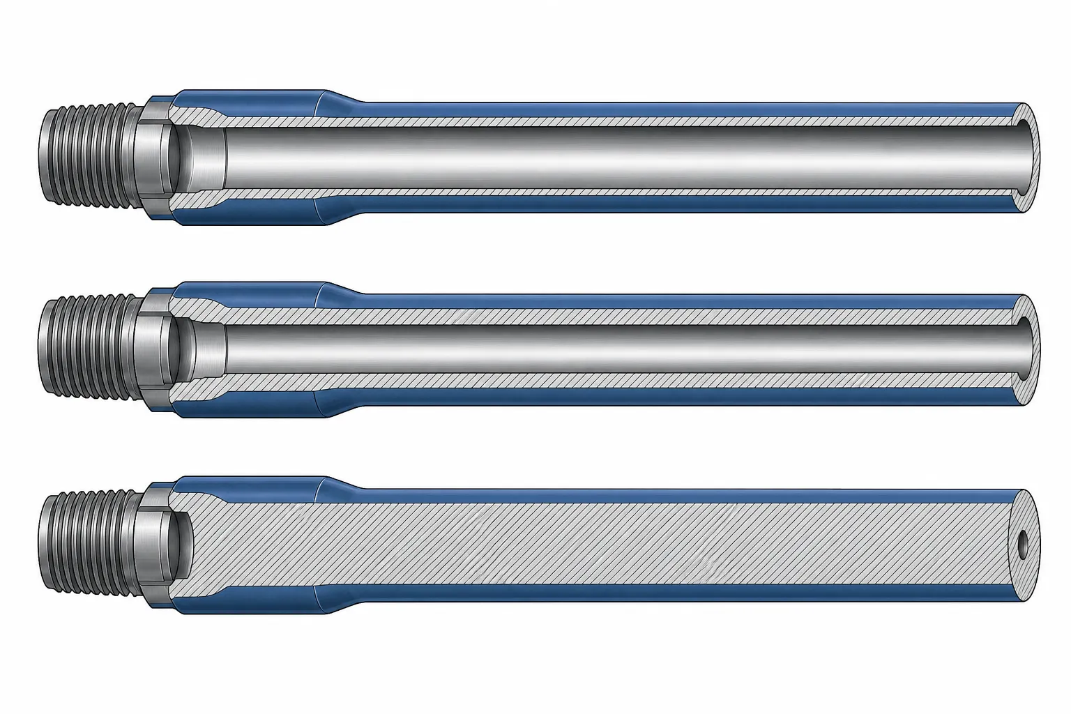
Spiral (grooved) drill collars exist for one downhole reason: the helical grooves reduce the contact area between the collar body and the wellbore wall, lowering differential sticking tendency and giving mud a flow path. That same groove pattern changes the straightening problem more than most shops expect. The collar is no longer a uniform round section — its wall, and therefore its local stiffness, varies cyclically along the length, alternating between full-diameter lands and reduced-wall groove roots at every pitch interval.
The correction rule that follows is geometric, and it is absolute: every ram foot and every support must land on a full-diameter land, centered on it, with the groove spans treated as no-contact zones. Pressing into a groove root concentrates the same ram force into a thinner local section — the plastic zone deepens disproportionately there, and the groove profile itself deforms. A flattened or bell-mouthed groove cannot be restored later without machining stock off the gauged body, which is why the land rule belongs in the fixture design, not in operator training alone.
Land discipline is really an indexing problem. Because the grooves spiral, the lands rotate along the length: the press point, the support stations and the measured high point each sit at different clock positions, and a fixture that cannot index the collar rotationally cannot guarantee land-centered contact at every station. Practical spiral-collar cells therefore work with rotatable, land-aware supports — or at minimum with marked clock positions — so that each press cycle re-establishes contact on sound metal before force is applied. This is the same land-indexed fixturing logic summarized in the FAQ below, applied as machine design rather than as an operator memory exercise.
Two process consequences deserve attention. First, available press points are discrete: where a slick collar offers a continuous contact line, a spiral collar offers a series of short land windows, so support spans are chosen from a shorter menu, and a stubborn bow may need more cycles at smaller increments rather than one large press. Second, springback is phase-dependent: section stiffness at a land differs from stiffness near a groove root, so compensation factors validated on slick collars do not transfer — they are re-established per joint family, following the general discipline in shaft straightening springback compensation. The route logic itself does not change: spiral collars remain press work, for the reasons set out in press straightening vs roller straightening — rolling would bridge the grooves and work-flatten the lands continuously.
Closed-Loop Cycle and Crack Discipline
A defensible collar straightening cell runs measure-press-remeasure as a closed loop: initial multipoint bend map, press increment sized from measured deviation and section stiffness, re-measure on the same datums, iterate until inside the acceptance band, then re-check after a settling interval. The reason for the settling re-check is stress relaxation — freshly pressed curvature can drift as residual stresses redistribute, the same mechanism analyzed for general shafts in our straightening after heat treatment discussion.
Crack discipline is the collar-specific safety layer. Collar steels are through-hardened, high-strength sections; over-pressing a local zone can initiate subsurface cracks that later NDT may catch — or miss. Practical discipline: cap press increment per cycle, keep correction count finite and logged per joint, and surface-inspect pressed zones after the final cycle. Automated cells enforce this with per-part correction counters and defect-route logic, the same sorting discipline described in our NOK sorting and rework-limit article for straightening lines.
Common Failure Modes We See in RFQs
- Requesting a machine rated for string pipe and discovering mid-project that collar force requirements exceed it — always qualify by section modulus, not by “pipe size”.
- Planning to press across spiral grooves or slip recesses because the fixture arrives without land-mapping provisions.
- Measuring acceptance with a single straightedge check while the customer’s BHA runout requirement is actually a connection-to-body coaxiality figure.
- No settling re-measure, so joints pass at the press and drift out of band in the yard.
- Blanket re-pressing of fatigue-curved joints without an engineering disposition step — a safety issue disguised as a yield issue.
Checklist: What to Bring to a Machine Conversation
To size equipment and fixtures for drill collar work, a supplier needs: collar OD range and lengths; body style (slick / spiral, groove geometry if available); steel family and typical hardness; whether joints arrive with connections made up; initial and target straightness bands with the governing standard reference; measurement method required for acceptance; expected annual volume and mix between OEM and reconditioning flow; and handling constraints in your hall (crane capacity, bay length). With that set, a sample-part test on your actual joints — not on stand-in pipe — is the only honest way to fix press capacity, support span and cycle time.
FAQ
Can a bent drill collar be straightened at all?
Handling-type bends and local doglegs are routinely pressed back into tolerance at inspection shops. Whether a specific joint should be depends on its service history, crack inspection results and remaining fatigue margin — those dispositions belong to the inspection engineer, not the press operator.
What straightness is required?
Acceptance limits for drill string components are set by the applicable API specifications and by company inspection standards applied at the category level. A frequently cited order of magnitude for string tubulars is total deviation on the order of a fraction of one percent of length, but the binding value is always the current edition of the governing standard plus the owner’s in-service class limits — never a number from an article, including this one.
Spiral vs slick collars — different machines?
Same press route, different fixturing and protection logic: spiral collars demand land-indexed supports and ram feet that avoid groove spans, which is a fixture and control detail rather than a fundamentally different machine architecture.
Portable press or fixed machine?
Portable gag presses dominate field and small-shop reconditioning; fixed servo press cells with rotating measurement suit OEM lines and volume inspection yards that need logged, repeatable results and lower operator dependency. The trade-offs mirror our manual vs automatic straightening analysis.
Summary and Next Step
Drill collar straightening is a heavy-section, crack-sensitive press process that pays for itself both on OEM lines and in inspection reconditioning loops. Get the family boundaries right (pipe vs HWDP vs collar vs production tubing), map the bend before pressing, respect protection zones, and close the loop with settling re-measurement. If you are evaluating equipment for collar-grade work, send the checklist data above plus one representative bent joint — a measured sample test is the fastest way to a defensible machine specification.