
A rotating indicator trace can contain several effects at once. It may reflect the workpiece axis, local roundness, cylindrical form, a datum relationship, support seating, fixture error, probe setup or an interrupted feature. Calling every high reading a “bend” can lead to the wrong correction action and can damage a part that actually needs a measurement or machining review.
This guide explains how to diagnose the signal before a straightening decision. It does not establish a StraighteningTech measurement system, tolerance, sensor resolution, datum procedure or correction capability. The controlled drawing and customer inspection method are required for final decisions.
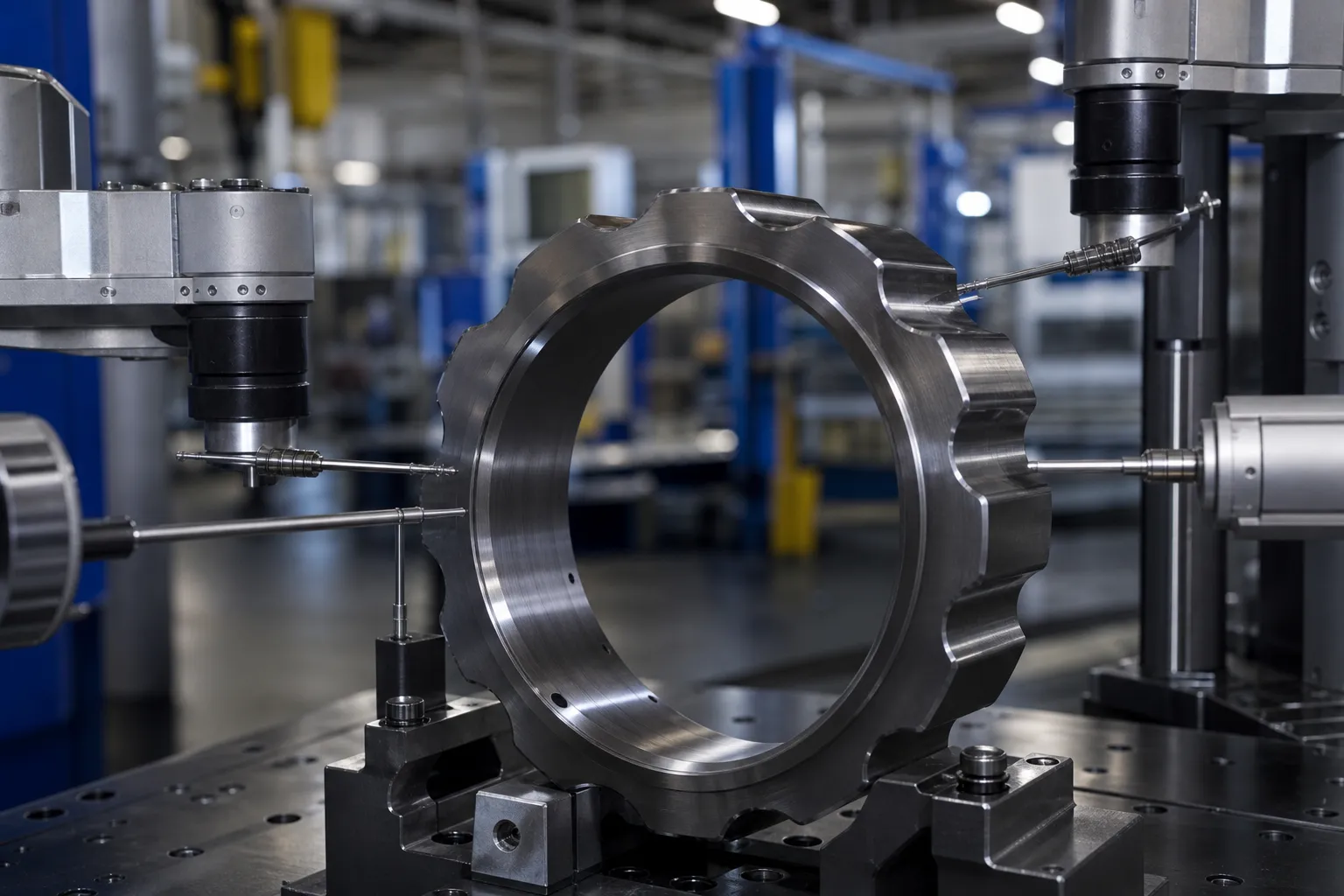
*Engineering concept illustration. It shows that a rotating signal can include form variation; it is not a measurement result for a customer part or a prescribed inspection setup.*
Name the Characteristic Before Reading the Gauge
Roundness describes a cross-sectional form condition. Axis bend describes the spatial path of a reference axis. Runout is a rotating measurement relative to a datum setup and can include multiple contributors. Coaxiality, concentricity and cylindricity also have distinct definitions and inspection requirements. The drawing must identify which characteristic controls acceptance.
| Signal or characteristic | Diagnostic question |
|---|---|
| Roundness / lobing | Does the local radius change as the section rotates? |
| Axis bend | Does the reference axis change position along the length? |
| Runout | Which datum, supports and probe station create the reading? |
| Coaxial relationship | Are multiple features being compared to a defined common axis? |
| Fixture signal | Does reseating or changing support orientation change the result? |
See shaft straightness, runout and TIR and coaxiality versus runout for related terminology.
Inspect the Datum and Setup First
Before interpreting the part, verify the center features, journals or other reference surfaces, support condition, cleanliness, probe contact, rotation method and axial station. A damaged center, burr, dirty seat, incorrect support or probe contact on an interrupted surface can create an apparent runout that does not represent axis bend.
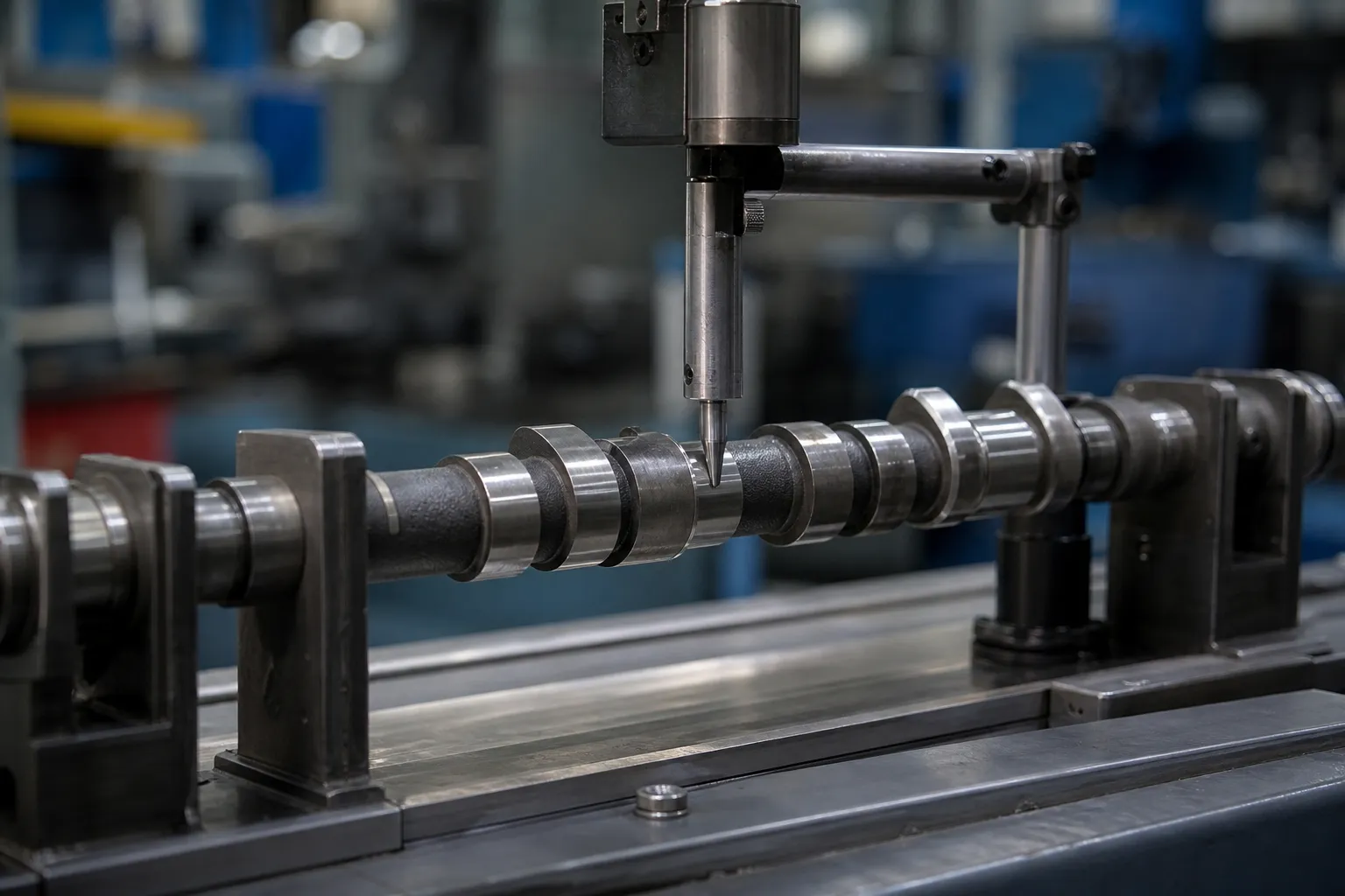
*Engineering concept illustration. It illustrates feature-aware journal measurement; actual datums, probe tracks and angular masks depend on the controlled workpiece.*
Use a reseat/repeat check and compare multiple stations. If the trace changes substantially after setup is repeated, investigate fixture or datum realization before applying correction force.
Compare Multiple Stations and Orientations
Axis bend usually requires an axial map. Local roundness or lobing may appear at one station but not another. A single total indicator reading at one point cannot prove which contributor dominates. Record station locations, orientation, reference condition and the trace or calculated result required by the acceptance procedure.
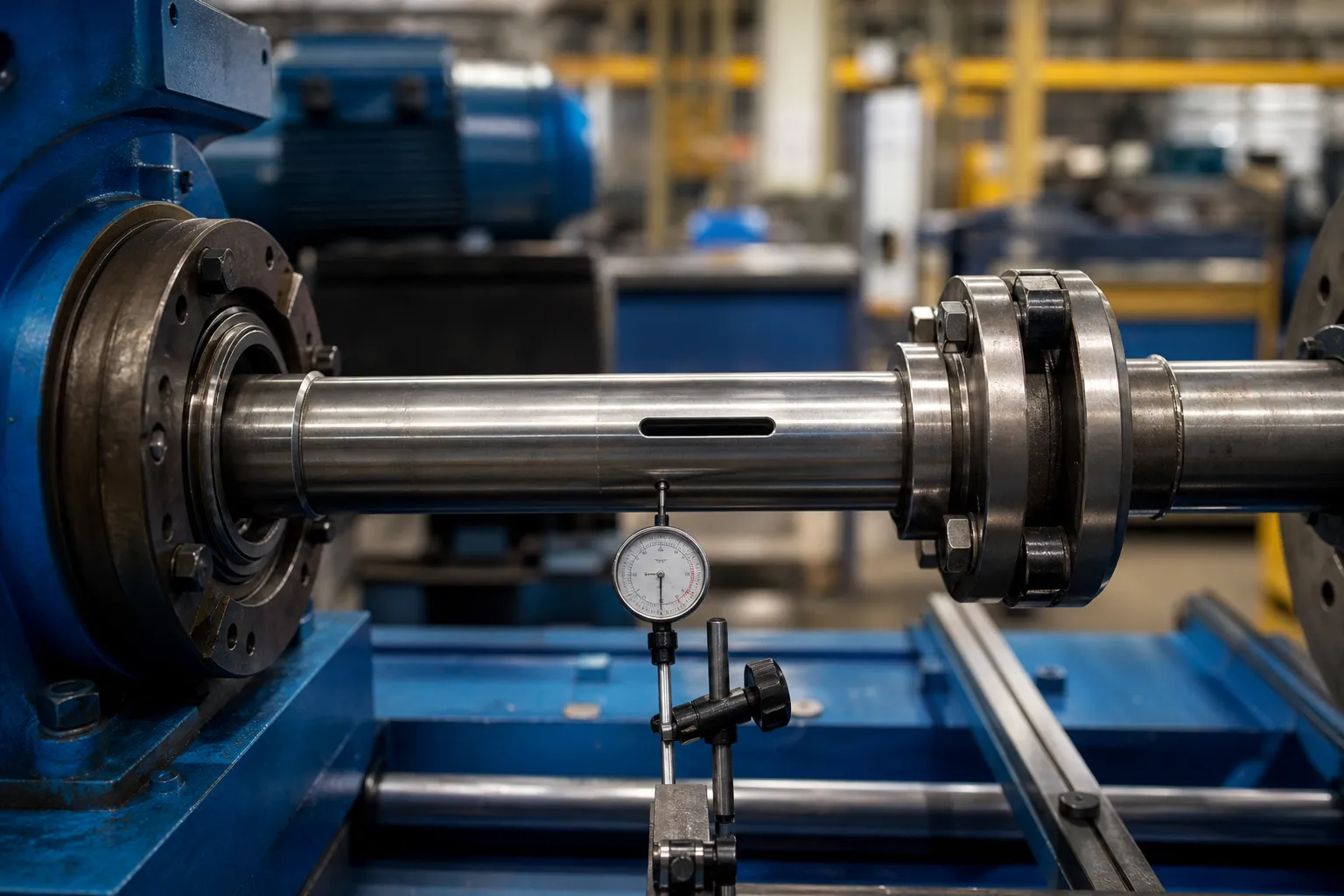
*Engineering concept illustration. It represents a multi-feature rotational measurement question, not an approved fixture or a conclusion that the observed signal is bend.*
Select the Response From the Diagnosis
If the evidence supports an axis-bend condition and there are approved contact/support zones, a candidate straightening route may be evaluated through a sample test. If the signal is mainly roundness, interrupted geometry, a datum issue, fixture error or a separate feature relationship, a different process or inspection review may be required. Do not use straightening to compensate for a measurement problem.
For controlled local correction, see point-press straightening. For correlation to the final inspection method, see machine gauge versus customer gauge correlation.
Validate With the Customer Gauge
The sample plan should include known/reference conditions where available, repeat setup, multiple stations, released-state measurement, part and fixture identification, raw data retention and customer-gauge correlation. The result should state which characteristic was evaluated and which uncertainty or setup limitations remain.
FAQ
Does high TIR always mean the shaft is bent?
No. TIR can include datum, roundness, fixture and other contributors. Diagnose the setup and multiple stations first.
Can straightening correct roundness?
Not as a general conclusion. Roundness is a different geometric condition and may require a different process or inspection route.
Why repeat the setup?
Rereading after reseating helps distinguish a workpiece signal from support, datum or fixture variation.