
Gun drill and deep-hole drill straightening is a specialised manufacturing-stage problem. A drill is not a plain round shaft: the shank, flute, cutting head, coolant features, heat-treatment condition and later grinding or regrinding operations can each change where the tool may be supported, measured and corrected. A process that only makes the tool appear straight can still damage a protected feature or use a datum that does not represent functional inspection.
This article provides a sample-test framework, not a promise that StraighteningTech supports every drill geometry or size. The final process depends on the drawing, representative tools, material state, permitted contact zones and the customer's released-state inspection method.

*Engineering concept illustration. It shows a candidate long-tool correction context; it is not a customer machine record or evidence of a guaranteed drill result.*
Define the Tool Family and Exclude Look-Alike Intents
The exact query produces a specialist deep-hole-drill straightening result, but also drilling-machine, regrinding, gun-barrel and general hydraulic-straightener results. Those are separate intents. The scope here is a manufacturing-stage gun drill or deep-hole drill whose geometry must be evaluated before its next approved operation.
| Include | Exclude |
|---|---|
| Straightness or runout evaluation of a controlled drill family | Deep-hole drilling machine selection |
| Shank, flute and head protection during a candidate correction trial | Regrinding, sharpening or bore-making service |
| Sample-based datum and released inspection planning | Gun barrel, concrete drill and medical-drill claims |
The article should link to the existing drilling tools straightening scope but not silently treat that broad hub as proof that every gun drill is already covered.
Trace Distortion to the Manufacturing Stage
Tool geometry can be affected by raw-material condition, machining, flute formation, heat treatment, surface finishing, handling or an earlier correction attempt. The timing changes the permitted contact strategy. A blank that will receive later grinding may be reviewed differently from a finished drill with protected cutting features.
Before a trial, identify the controlled tool drawing, material and heat-treatment state, length and changing diameter, shank/end geometry, flute/head features, current manufacturing stage, incoming deviation map and next process. Do not copy competitor dimensions, number of axes, force, cycle time or automation claims into a local specification.
Why Deep-Hole Tools Distort the Way They Do
A gun drill earns its distortion. The raw drill rod is already extremely slender — length-to-diameter ratios that would embarrass a transmission shaft — and then the manufacturing route removes material asymmetrically: fluting or milling a chip channel along one side, cutting the driver flat, adding the head with its cutting geometry and coolant passage. Every one of those operations removes constraint from where it was and leaves residual stress where machining worked the material. Heat treatment then adds its signature on the now-asymmetric section, and deep-hole drilling the coolant bore through the core disturbs the stress balance a second time. The finished tool is a precision instrument carrying several overlaid distortion fields. Understanding this stack is practical, not academic: it predicts that bends concentrate near section transitions — head to flute, flute to shank — that the same tool design can distort differently across lots, and that a correction process which treats the tool as a plain bar will both measure and press in the wrong places. The staging logic and its interaction with correction are the same covered for straightening after heat treatment, applied to a section that never had symmetry to begin with.
The Asymmetry Problem: Fluted Sections Are Not Shafts
On the fluted length, the cross-section is an open profile with a neutral axis displaced away from the geometric center — the material web and the chip channel do not balance. Two engineering consequences follow. Stiffness becomes directional: the section bends more easily in the plane of the flute than perpendicular to it, so the same correction stroke delivered at the same force produces different movement depending on the tool’s clocking — the correction plan must therefore be orientation-aware, not just position-aware. And measurement on the flute reads a surface that is spiraling: a probe tracking the OD of a fluted tool sees the flute pass as an interruption, and the residual OD between flutes follows a helix, so naive readings mix the helix geometry into the axis map. The disciplined answers are angular masking — read only in defined rotational windows between flutes — and separating the shank, where the section is solid and behaves classically, from the fluted length, where every number needs its context. The same interrupted-surface caution applies to the rock-drill and heavy-tool families covered under heat-treated drill rod straightening.
Choose a Functional Datum and Measurement Map
Straightness, radial runout and cutting-head relationship are not interchangeable. The customer drawing must state which characteristic controls acceptance and how the tool is supported or rotated. A shank can be a candidate reference only if it matches the required functional axis and its condition is controlled.
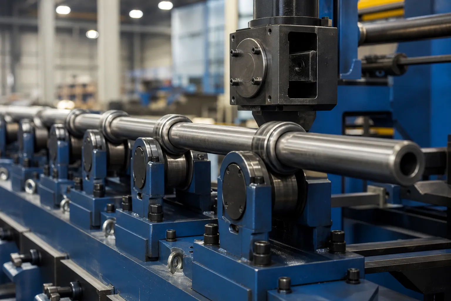
*Engineering concept illustration. It emphasizes that long slender tools need support planning; exact station count and sensing method must be validated from the drill family.*
The measurement review should record approved reference features, axial stations, rotation method if used, probe contact conditions, angular masks for flutes or holes, support locations and the released condition used for final acceptance. A local feature or unsupported span can otherwise be mistaken for a whole-tool bend.
Protect the Shank, Flute and Cutting Head
Support and correction locations must be approved from the geometry map and protected-zone review. Flutes, cutting edges, coolant holes, coated zones and local changes in section can create both contact risk and misleading measurement. An accessible surface is not automatically an acceptable load point.
| Zone | Engineering question |
|---|---|
| Shank | Does it establish the functional datum and tolerate the proposed support? |
| Flute | Can probe or support contact avoid interrupted-surface signal and marking? |
| Cutting head | Is contact prohibited because it can affect edge geometry or subsequent finishing? |
| Slender span | Does support spacing prevent sag from becoming an apparent correction target? |
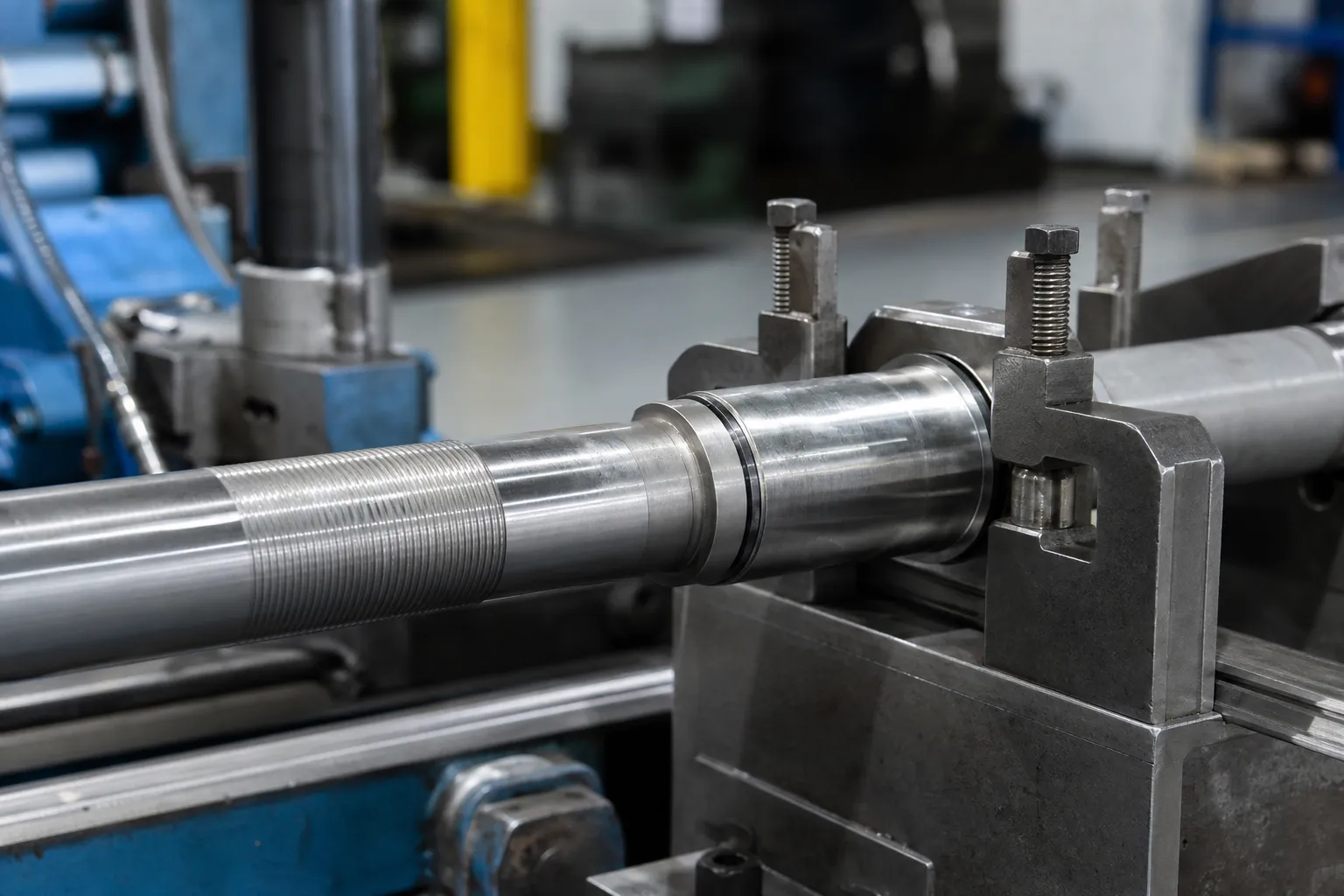
*Engineering concept illustration. It shows an incremental correction concept, not an approved pressure, stroke, fixture or production recipe.*
Where Straightening Sits in the Tool’s Process Route
The same tool asks a different straightening question depending on where it stands in its route. A blank or semi-finished rod, heading into grinding, offers contact freedom — surfaces that will be removed anyway tolerate correction marks that a finished tool cannot — and its acceptance question is whether the grinding allowance can clean up the corrected geometry. A finished drill, flutes cut and edges prepared, inverts every priority: protected zones dominate, corrections must land on the plain spans, and the acceptance question is functional runout on the customer’s own inspection. A reground tool arrives with its straightness history already spent once and its dimensions changed from nominal, so the correction recipe it ran under as a new tool no longer describes it — the rework rules and deformation budget from the rework-limit framework apply with full force. Freezing the manufacturing stage in the trial record, as the framework above requires, is what keeps these three conversations from blurring into one expensive misunderstanding.
Handling Interrupted Surfaces in the Measurement
Practical measurement plans for fluted tools converge on a small set of techniques, each with a cost. Angular masking — sampling only in the windows between flute passes — keeps the probe on continuous material at the price of fewer readings per revolution and a defined rotational reference to keep the windows aligned between stations. Shank-based mapping — measuring the solid sections precisely and interpolating across the fluted span — gives clean numbers at the ends but assumes the fluted length behaves smoothly between them, an assumption the distortion physics occasionally betrays near the head. Feature-aware fixturing — supporting on the land between flutes with conformal tooling — preserves the tool’s attitude but makes support condition part of the measurement definition, to be held identical between the machine and any verification station, per the datum discipline in stepped shaft measuring datum selection. Whichever combination a process adopts, the rule that decides its credibility is unchanged: reseat and repeat, and treat any peak that fails the reseat check as a hypothesis rather than a correction target.
Use an Incremental, Released-State Correction Loop
- verify the approved drill family, manufacturing stage and incoming condition;
- inspect for damage, out-of-scope deformation or prohibited surface condition;
- establish and verify the datum and support setup;
- map the agreed geometry before correction;
- select only approved supports and correction points;
- apply an incremental correction within the sample-test limit;
- fully release the tool and restraint;
- remeasure and record OK, NOK or engineering-review disposition.
The final decision must follow release. A reading while a tool is clamped or under force cannot be presented as final straightness or runout.
Build Acceptance Around Representative Tools
The sample package should include normal and worst-case incoming drills, the controlled drawing, reference gauge, measurement correlation, protected-surface inspection and an explicit no-progress limit. Where crack or material-integrity concerns apply, formal NDT remains a separate process unless the responsible method is specified and qualified; correction monitoring does not automatically replace it.
For the broader acceptance workflow, see straightening sample test and acceptance and shaft straightness, runout and TIR.
Information Needed for a Gun Drill Straightening Review
Provide the controlled drawing, tool type, material and heat-treatment state, manufacturing stage, shank/flute/head detail, representative normal and bent samples, incoming geometry data, protected-contact requirements, reference inspection method and production target. StraighteningTech can then review candidate datum, support, measurement and correction architecture before proposing a sample-test plan.
FAQ
Is gun-drill straightening the same as a gun-drilling machine?
No. A gun-drilling machine makes a bore. This article addresses a controlled geometry review of the tool itself during manufacturing.
Can a flute be used as a general measurement surface?
Not without a feature-aware method. Interrupted geometry can create false probe signals and may be a protected zone.
Can an accuracy or cycle time be guaranteed from the article?
No. Both require validated samples, the agreed datum and inspection method, and a verified machine-and-tooling configuration.
Why do gun drills bend near the head and the flute runout?
Because stiffness changes abruptly at those transitions and the manufacturing route removed material asymmetrically around them. Stresses from fluting, heat treatment and the coolant bore concentrate where the section changes, so the correction map usually shows its peaks near the head-to-flute and flute-to-shank boundaries rather than at mid-length.
Does flute direction affect the correction plan?
Yes. A fluted section bends more easily in the flute plane than across it, so the same press stroke moves the tool differently depending on clocking. Correction plans for fluted tools are orientation-aware: the press point, direction and tool rotation are specified together, not independently.
Should a blank be straightened before or after flute milling?
The route decision belongs to the tool process engineer, but the trade is explicit: straightening the solid blank is contact-friendly and geometrically simple, yet fluting and heat treatment afterward can distort it again; straightening the fluted, heat-treated tool faces protected zones and interrupted measurement but corrects the geometry the finished tool actually carries. Whichever stage is chosen, the acceptance definition and correction validation must be run on tools in that state.
Comparing suppliers for gun drill and deep-hole drill straightening? Take the selection guide for shaft, tube and profile work with you, and sanity-check pricing against the straightening machine cost breakdown.