
Büyük döküm yapısal parçalar karmaşık olabilir, ince duvar geometrisi ve çoklu işlevsel arayüzler. Güvenilir bir 3D doğrultma sistemi veriyi ve fikstür stratejisini kontrol etmelidir, ölçüm durumu, çok noktalı düzeltme konsepti, temas/yüzey riski, çatlak riski incelemesi ve yayımlanan geometri. Genel bir baskı veya yayınlanmış bir rakip mimarisi, bir tedarikçinin bu işi yapabileceğinin kanıtı değildir..
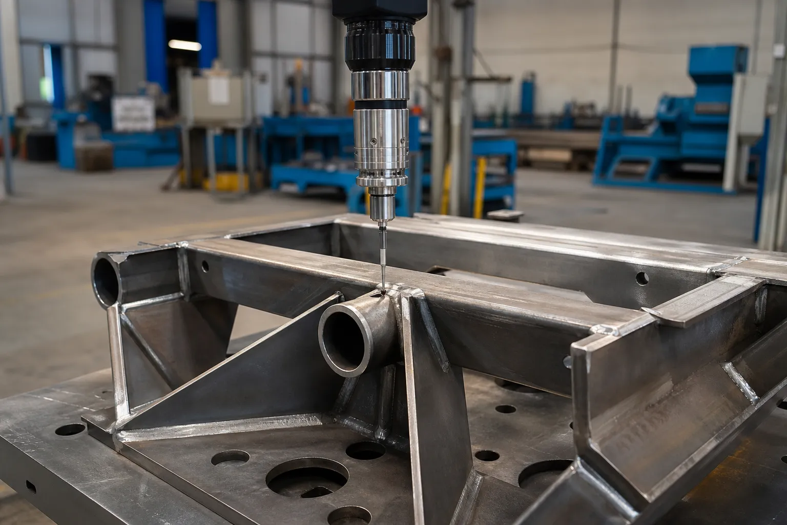
*Mühendislik konsept illüstrasyonu. Doğrulanmış bir düzeltme dizisi göstermez, aktüatör seti veya yapısal parça sonucu.*
Zorlamayın, aktüatör sayısı, döngü süresi, tolerans, proje kanıtı olmadan çatlak tespit oranı veya uyumlu döküm tipi. Bu değerler kağıt üzerinde veya rakip bir sistemden aktarılamaz.
Büyük Dökümler Dökümden Sonra Neden Hareket Ediyor?
Dökme yapısal parçalar, katılaşma ve soğuma değişen kalınlıktaki bir bölüm boyunca hiçbir zaman tekdüze olmadığından deforme olur. Kalın özellikler yavaş soğur ve ince duvarlara göre daha geç büzülür, böylece döküm kalıptan veya kalıptan kilitli bir artık gerilim alanıyla ayrılır. Bu stres alanı parça üzerinde görünmez; ancak kendisini daha sonra duyurur, bir şey değiştiğinde. Fırlatma, kırpma, ısıl işlem, kumlama, ve her şeyden önce makineyle işleme kısıtlamalarını kaldırın veya yeniden dağıtın, ve parça yeni bir dengeye doğru hareket eder. Döküm durumunda kabul edilebilir olarak ölçülen bir arka yapı dökümü, kritik arayüzler işlendikten sonra konum toleransının dışına çıkabilir, because removing material from one face releases the balancing stress on the opposite side.
This is why distortion control on structural castings is a sequence problem, not a single-press problem. The timing of the straightening operation inside the process route — before stress relief, kaba işlemeden sonra, before finish machining — changes both how much correction is needed and how stable that correction remains. Each of those routes has different risk: correcting an as-cast part may be undone by later machining, while correcting a finish-machined part risks damaging functional surfaces. The route decision belongs to the responsible process engineer, with the distortion history of the part in view.
What Makes Correction “3D” Instead of Planar
Conventional bar and shaft straightening corrects a centerline that is, to first order, a plane curve: bow in one plane, sometimes bow measured in two perpendicular planes and combined. The machine finds the high point of the bend, supports the part on two anvils, and presses at the peak. The geometry being controlled is a single neutral axis. This is the model behind otomatik mil düzeltme nasıl çalışır, and it assumes a stiff, uniform section.
A thin-wall structural casting breaks those assumptions. The section is not uniform — rails, kaburga, bosses and window openings give it direction-dependent stiffness, so the same applied force produces different deflection depending on where and in which direction it acts. The deviation is not one bend: it is a combination of bow in one axis, sweep in another, twist about the longitudinal axis, ve bireysel fonksiyonel arayüzlerin yerel yer değiştirmesi — bir ucunda yüksekte oturan bir montaj pedi, veri sistemine göre eğimli bir delik ekseni. Ölçülen büyüklük, parça koordinat sistemindeki her işlevsel arayüzün konumu ve yönelimidir, tek bir tükenme okuması bile yok. Yalnızca genel bir yayı takip eden herhangi bir düzeltme planı, hareket ettirmeyi düşünmediği arayüzleri hareket ettirecektir..
Pratik olarak, bu, yapısal döküm için hata haritasının arayüz sapmalarının bir tablosu olduğu anlamına gelir, bir merkez çizgisinin kutup diyagramı değil. Bu aynı zamanda düzeltme hedeflerine öncelik verilmesi gerektiği anlamına da gelir: sıkı konum toleranslarına ve montaj ilişkisi sonuçlarına sahip arayüzler ilk sırada gelir, ve ikincil geometrinin kendi tolerans bantları içinde yüzmesine izin verilir. That prioritization is a drawing-driven engineering decision made before any press stroke is planned.
Datum and Fixture Strategy Comes Before Correction
Measurement and correction of a casting are only as good as the datum system they reference. As-cast surfaces are draft angles and skin — they are neither repeatable nor representative. The part must be located on its drawing-defined machined datums, the same features the customer gauge will use at acceptance. If measurement uses one set of features and the customer gauge uses another, the two systems will disagree by setup error alone, before any real part variation enters. The principles are the same as those covered for kademeli mil ölçüm verisi seçimi, applied to a far less symmetric workpiece.
Fixtures for thin-wall castings carry an additional burden: the clamping and support scheme must not load the part into a false shape. A casting supported at the wrong points deflects under its own weight and under clamp force, and the measurement system will faithfully record that deflection as part error. Supports belong under stiff sections — ribs, rails, boss clusters — not in the middle of window openings. Every fixture concept should be proven by reseating: ölçüm, unload, reload, measure again, and treat the spread between those readings as the floor of what the system can resolve. If reseating repeatability is poor, no amount of correction accuracy downstream will close the loop, a lesson that also drives R ölçer&R practice for straightening lines.
Correction Concepts and Their Limits
The mechanical idea behind correcting a casting is selective local plastic deformation: apply force at chosen points to shorten one side of the structure or shift its stiffness balance, so the released part settles closer to nominal. Two families of concepts exist. Point pressing — the same family described for noktaya basarak düzleştirme — concentrates deformation at a support-and-press location and is best suited to localized deviations on stiff sections. Distributed or multi-point methods spread smaller corrections over several locations to reshape a longer span. Which concept fits a given casting depends on where the deviations sit and how the stiffness varies between them, which is exactly why a generic press specification answers nothing.
Three limits bound any correction route. Birinci, cast aluminum has limited ductility compared with drawn bar stock, and a thin-wall section concentrates strain: the crack-risk review — where cracks are likely, how they will be looked for, and who accepts the result — must be settled before the first trial stroke, not after a suspect part appears. Saniye, correction interacts with the residual stress field that caused the distortion. A correction imposed without regard to that field can relax during subsequent handling, machining or thermal exposure; stress behavior after correction is a topic treated separately for ısıl işlem sonrası düzleştirme. Üçüncü, over-correction on a casting is usually not recoverable by pressing back, because reverse loading accumulates low-cycle fatigue damage in the section.
The discipline that manages all three limits is the same incremental loop used on precision shafts: small correction, serbest bırakmak, yeniden ölçmek, decide. The measure–correct–release–remeasure cycle described for long structural sections such as elevator guide rails scales down to castings in principle, but with one added rule: because interface positions rather than a single centerline are the target, each loop must re-read the interface table, not just the worst single reading.
Ölçüm, Integrity and Release Must Agree
The development record should preserve incoming geometry, datum/fixture setup, measurement method/data version, düzeltme sırası, serbest bırakılan geometri, surface/inspection findings and disposition. If integrity inspection is required, its method, scope and acceptance authority must be specified by the responsible engineering and quality teams.
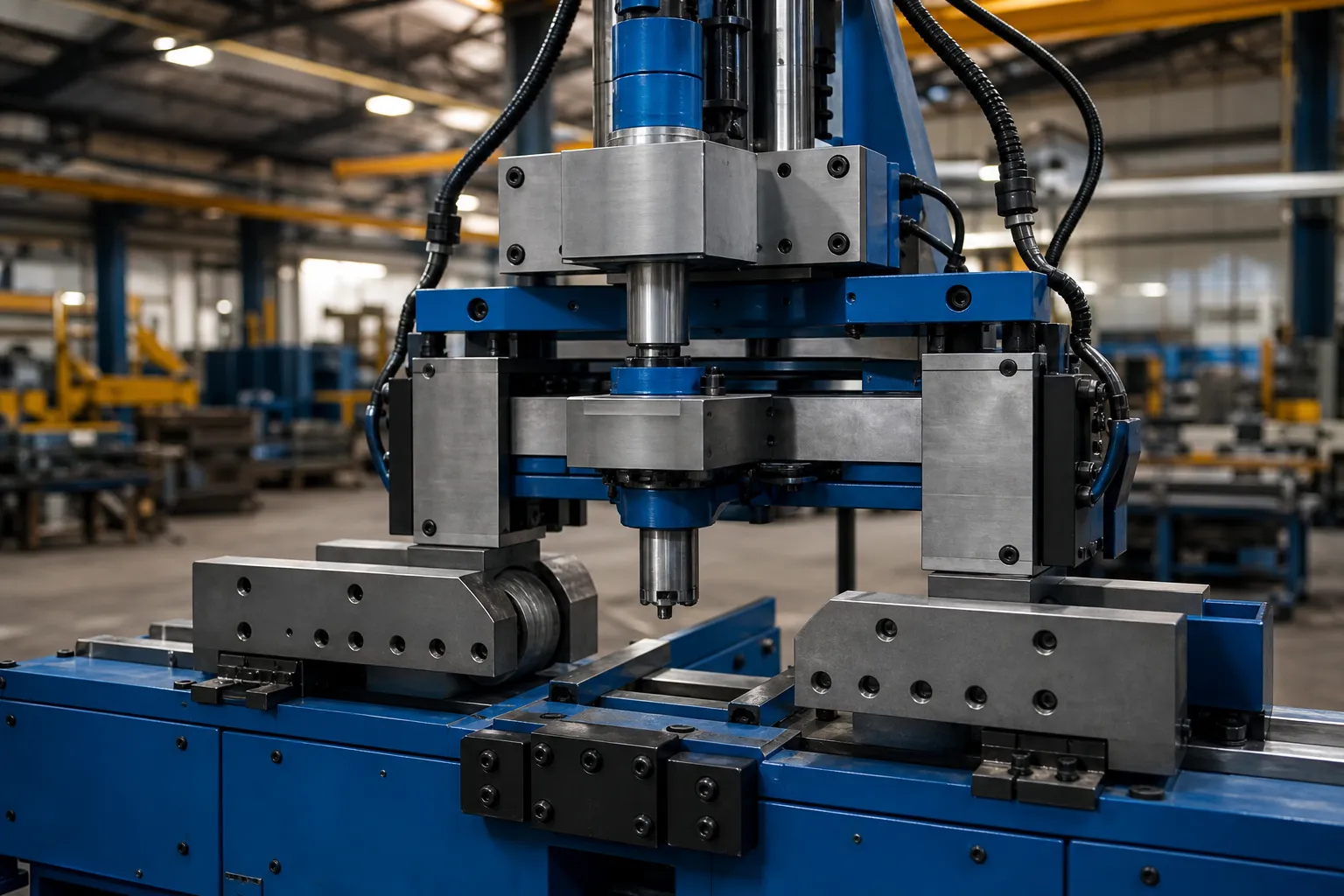
*Mühendislik konsept illüstrasyonu. It is not proof of available equipment, safety design or a giga-casting application.*
Görmek Fikstür tekrarlanabilirliği ve veri oturması Ve Doğruluk muayenesinde ölçüm belirsizliği for relevant controls; neither provides 3D casting capability evidence.
Evidence Required Before Any Supplier Claim
An OPEN publication decision requires a real authorized casting project, drawing-defined 3D datum and fixture, measurement-before/after/release data, correction records, yüzey/bütünlük incelemesi, kabul edilen örnekler ve müşteri yetkilendirmesi. O zamana kadar bu sayfa bir araştırma çerçevesi olarak kalacak. Kapsamlı bir mühendislik tartışması için, StraighteningTech ile iletişime geçin yetkili proje bilgileri ile.
Sistem Talebinden Önce Gerekli Doğrulama
Any system claim for giga-cast correction needs a defined workpiece scope, calibrated datums and fixtures, izlenebilir ölçüm verileri, and correlation with the customer’s own gauge. Genel makine yeteneği bu konu için doğrulanmış bir sonuç değildir.
SSS
Can a giga-cast structural part be straightened on a bar straightening machine?
Not as a drop-in. Bar straightening machines assume a uniform stiff section and a single centerline error. A thin-wall structural casting has direction-dependent stiffness, twist and interface-position deviations, and needs a datum, fixture and measurement concept built around its drawing — plus a crack-risk review appropriate to cast ductility. Some underlying correction physics is shared; the workholding, measurement and validation are not.
Should stress relief come before or after straightening a casting?
That depends on the distortion history and the process route, and it is a decision for the responsible process engineer. Correcting before stress relief risks later relaxation of the correction; correcting after removes one instability source but may face harder material. What should be non-negotiable is that the choice is deliberate, documented, and consistent between the trial and production.
What evidence should a buyer request before accepting a 3D straightening proposal?
A drawing-defined 3D datum and fixture concept, measurement data in the as-received and released states, the correction record for every trial part, an integrity or crack-inspection scope agreed with the quality team, and acceptance judged on the customer gauge. A proposal that offers only machine specifications, without those items, is not a proposal for this work.
İlgili DüzleştirmeTeknik Kaynakları
Görmek otomatik mil düzeltme nasıl çalışır, numune testinin doğrultulması ve kabulü Ve şaft düzgünlüğü vs salgı vs TIR herhangi bir yetenek talebinden önce geçerli olan genel kontrol sınırları için 3D Giga-Cast Yapısal Parçaların Düzleştirilmesi.

*Mühendislik konsept illüstrasyonu.*
Giga-casting correction is an automation-first conversation – the manuel ve otomatik karşılaştırma addresses the process jump, ve Otomatik düzeltme için yatırım getirisi durumu addresses the capital question.