
Large seamless steel pipes can develop global bow, local bends or handling deformation after rolling, heat treatment, transport and storage. When a pipe is not straight enough, it may create problems during machining, welding, inspection, coating, assembly or field installation. For long and heavy pipes, the correction process must also distinguish actual deformation from the deflection created by the pipe's own weight.
This proposed solution is based on a customer range from OD 127 mm × 9.525 mm wall to OD 349.25 mm × 38.1 mm wall, with lengths from 1,828.8 to 12,192 mm. It combines controlled support, full-length measurement, hydraulic point press-straightening and remeasurement. The recorded requirement “1 in 1000 mm” must be clarified before quotation; it is provisionally treated as a possible 1 mm deviation per 1000 mm gauge length, not as a confirmed one-inch tolerance.

Seamless Steel Pipe and Project Requirement
The project covers a very wide pipe envelope. Outside diameter changes by almost three times, wall thickness changes by four times and total length changes from approximately 1.8 to 12.2 m. These differences affect stiffness, self-weight, support spacing, measuring method, required correction force and material handling.
Using 7,850 kg/m³ only as a preliminary steel-density estimate, the smallest stated size at the shortest stated length is approximately 50 kg, while the largest stated size at the longest stated length would be approximately 3,564 kg if those maximum dimensions occur together. The actual part schedule, steel grade and certified weights are required before the loading and support system can be sized.
| Project Item | Customer Input / Status |
|---|---|
| Workpiece | Seamless steel pipe |
| Outside Diameter | 127–349.25 mm |
| Wall Thickness | 9.525–38.1 mm |
| Length | 1,828.8–12,192 mm |
| Material Grade / Yield Strength | Not yet provided |
| Incoming Deformation | Range and bend distribution not yet provided |
| Recorded Straightness | “1 in 1000 mm”; unit, gauge length and acceptance method to be confirmed |
| Current Method | Skilled manual straightening reported by the customer |
| Main Goal | Reduce production time and dependence on highly experienced manual correction |
| Proposed Method | Heavy-duty hydraulic point press-straightening with measured support and remeasurement |
| Machine Model / Rated Force | To be confirmed by engineering calculation and representative sample testing |
Define Local and Overall Straightness Before Selecting the Machine
A statement such as “1 mm per 1000 mm” normally describes a local straightness check over a defined gauge length. It does not automatically define the maximum deviation over the complete 12.2 m pipe. Overall straightness may be measured relative to a chord, laser reference, specified supports or another standard method. These two controls can produce different acceptance results and should not be merged into one number.
The inspection condition must also define pipe orientation and support positions. A long pipe bends under gravity. If the machine supports it at different points from the customer's inspection station, the two systems can report different values even when neither measurement is defective. Gauge correlation therefore requires the same datum logic, agreed support layout and a repeatable method for separating self-weight deflection from permanent bend.
| Control Item | Required Definition |
|---|---|
| Local Straightness | Allowed deviation and exact gauge length, potentially 1000 mm |
| Overall Straightness | Full-length chord/axis requirement and measurement method |
| Measuring Datum | Pipe OD, centerline, reference generators or specified end features |
| Support Condition | Number, position, height and contact type of supports |
| Orientation | Fixed clocking position or rotation through defined angles |
| Ovality / Diameter | Required only if the drawing or standard controls it |
| Surface Acceptance | No unacceptable dents, local flattening or support/press marks |
Why Large Seamless Pipes Are Difficult to Straighten
The workpiece is hollow, so the press does not act on a solid section. A narrow punch or incorrectly positioned support can create local indentation, flattening or ovality even if the longitudinal bow improves. Contoured saddles must distribute contact over a suitable area, and the permitted contact stress must be validated for the actual OD, wall thickness, grade and temperature. The section-preservation rules for smaller hollow parts are covered in thin-wall tube straightening.
The length and weight range create a second challenge. A 12 m pipe cannot be treated as a short part placed between two fixed supports. Multiple powered or adjustable supports may be required to control sag, move the pipe through the measuring and pressing positions and prevent uncontrolled rolling. The support system is part of the metrology and straightening process, not only material handling.
| Workpiece-Specific Challenge | Risk | Required Control |
|---|---|---|
| Hollow circular section | Denting, flattening or ovality during point pressing | Wide contoured press shoe and saddles; force/stroke limits |
| 1.8–12.2 m length range | Self-weight creates false straightness readings | Defined support model and repeatable full-length measurement |
| Up to OD 349.25 × 38.1 mm | High and variable correction force | Grade/yield data, bend profile, calculation and sample validation |
| Potential multi-ton part | Unsafe or slow manual positioning | Powered rollers, anti-roll devices, crane/gantry interface and guarded movement |
| Several local bends | One correction changes neighboring sections | Full-length bend map and controlled correction sequence |
| Wide size family | Excessive changeover or wrong tooling | Size-specific recipes, adjustable supports and verified tooling set |
| Skilled manual process | Operator-dependent press point and stroke | Measured bend location, controlled correction and repeat verification |
Recommended Straightening Method
For large pipes with localized or multi-point bow, a hydraulic three-point press-straightening concept is the preferred starting point. The pipe is supported on two or more controlled saddles, the bend profile is measured, and a hydraulic ram applies an over-bending stroke at an approved location. Depending on the final layout, the pipe may index through a stationary press frame or a press/measuring frame may travel along the pipe.
A multi-roll straightener may be more appropriate for continuous production of uniform pipe sizes and distributed curvature. It is not automatically the best choice for a wide mix of large diameters, thick walls and localized bends. Final method selection must consider throughput, size mix, material grade, incoming deformation, ovality risk and whether the pipe can be rotated safely. Oil tubing and casing follow a related OCTG-specific route.
Proposed Automatic Straightening Process
The related 243-second video shows a large pipe inside a heavy vertical hydraulic press station with an elevated service platform and multiple support elements. It is useful evidence of the scale, press architecture and pipe-handling challenge. It does not visibly prove the measuring technology, rated force, final tolerance, automatic correction algorithm or production cycle, so those details remain subject to project confirmation.
| Step | Process | Engineering Purpose |
|---|---|---|
| 1 | Pipe identification and recipe selection | Match OD, wall, length, grade, tolerance and tooling |
| 2 | Loading and anti-roll positioning | Transfer a heavy pipe safely to controlled supports |
| 3 | Support-height setup and datum establishment | Create a repeatable condition for long-pipe measurement |
| 4 | Initial full-length measurement | Map local and overall bend before correction |
| 5 | Bend calculation and correction sequence | Select press point, support span, orientation and initial stroke |
| 6 | Pipe or frame indexing | Align the selected bend with the hydraulic correction station |
| 7 | Controlled hydraulic over-bending | Correct the pipe within force, stroke and ovality limits |
| 8 | Remeasurement and adaptive correction | Close the loop or stop at the validated process limit |
| 9 | Final straightness/ovality inspection | Verify every required characteristic using the agreed method |
| 10 | Data recording and unloading | Store results and move OK/NOK pipes safely out of the cell |
Loading, Support and Positioning
The pipe is transferred by crane, gantry, walking beam or powered roller system according to actual weight and plant flow. Anti-roll devices and positive stops are essential because a large round workpiece can move unexpectedly. Supports should be adjustable in position and height and should use replaceable, contoured contact surfaces suitable for the pipe finish.
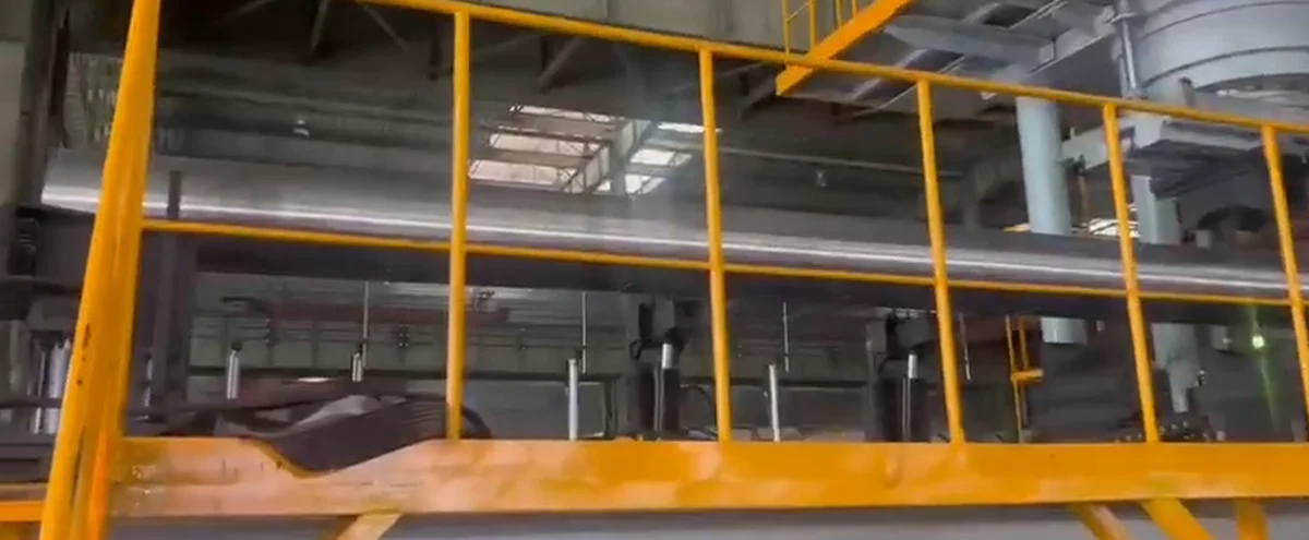
For long parts, support deflection and foundation level can influence the measurement. Commissioning should include support alignment, repeatability checks and a defined zero/reference procedure before production recipes are accepted.
Full-Length Bend Measurement
The measuring system may use laser scanning, contact displacement sensors or another validated method to record the pipe profile along its length. The measurement plan must specify resolution, gauge length, support condition, surface handling and whether the pipe is measured at one clock position or rotated to separate multi-plane bend and ovality.
If the customer uses a string line, straightedge or offline laser station, the automatic machine result should be compared with that method on the same sample set. The objective is not only repeatability inside the machine, but agreement with the final acceptance method.
Hydraulic Correction with Section Protection
The controller selects a correction point and support span based on the measured bend. A contoured press shoe distributes load over the pipe surface, while two or more saddles create the reaction points. The stroke must exceed elastic deflection enough to produce controlled permanent correction, but remain below limits that could dent, flatten or crack the pipe.
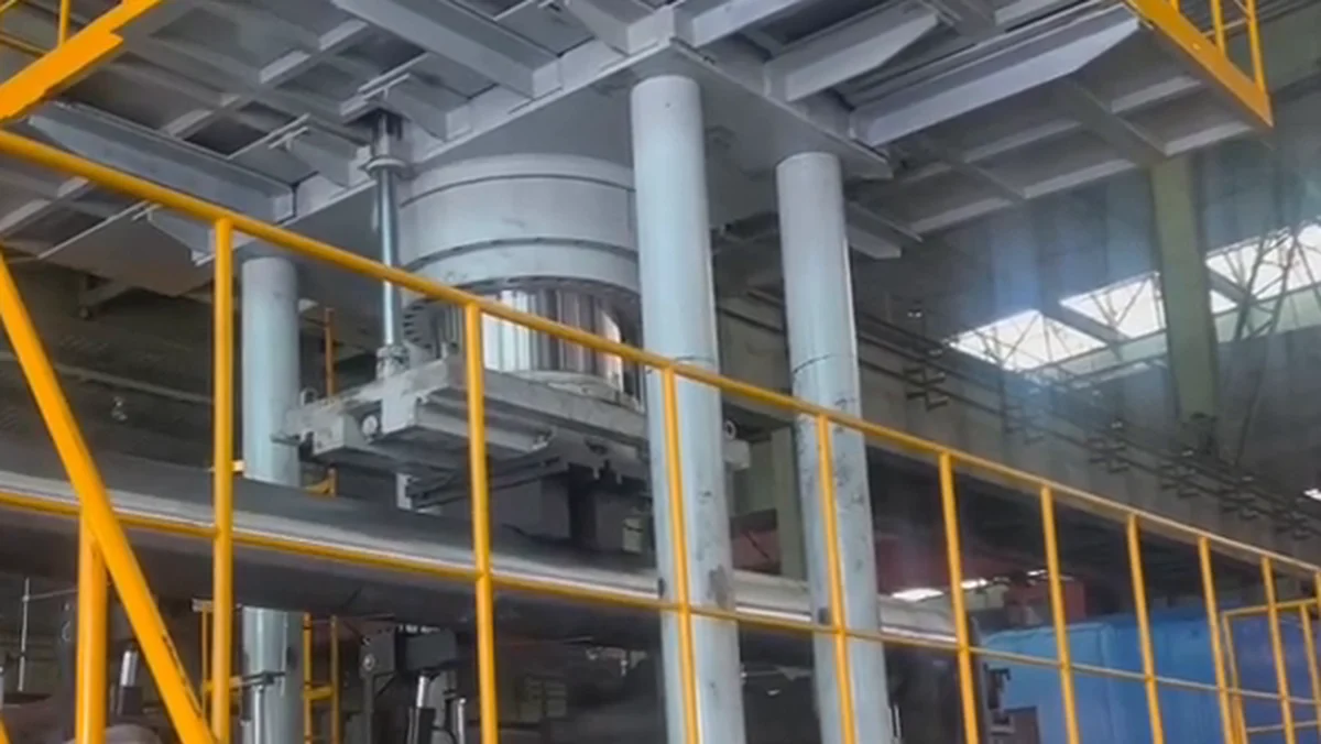
Rated force cannot be selected from outside diameter alone. It depends on wall thickness, steel grade and yield strength, support span, section modulus, incoming bend, desired residual result and allowable local stress. Initial force/stroke limits should be established by calculation and representative sample tests.
Remeasurement, Iteration Limits and NOK Handling
After correction, the pipe is measured again under the same support condition. If the result remains outside tolerance but the measured response is normal and the recipe is within its validated limits, the system may calculate another correction. Maximum stroke, force, correction count and abnormal-response rules prevent uncontrolled repeated pressing.
A pipe that cannot reach the target safely should be classified as NOK or sent for engineering review. The machine should retain the before/after profile, correction positions, strokes/forces where available, recipe version and final decision when project traceability requires it.
Recommended Cell Configuration
| Module | Proposed Requirement | Why It Is Needed |
|---|---|---|
| Machine Concept | Heavy-duty hydraulic three-point pipe straightening press | Local, controlled correction for large hollow sections |
| Workpiece Envelope | OD 127–349.25 mm; wall 9.525–38.1 mm; length 1,828.8–12,192 mm | Covers the stated project range, subject to size schedule confirmation |
| Rated Force / Stroke | To be sized by calculation and sample test | Prevent undersizing, excessive stress or misleading model selection |
| Measuring System | Full-length laser/contact profile measurement as validated | Distinguish local and overall bend and support closed-loop correction |
| Supports | Powered/adjustable contoured saddles with defined height and spacing | Control self-weight and protect the pipe surface |
| Positioning | Powered rollers, indexing drive or movable press frame | Bring each measured bend to the correction point safely |
| Tooling | OD-specific press shoes and saddles | Reduce indentation and ovality risk |
| Controls | Size recipes, bend map, correction limits and remeasurement logic | Reduce dependence on manual judgment |
| Handling | Crane/gantry/walking beam/roller interface with anti-roll control | Manage an estimated part range that may extend into multiple tonnes |
| Quality Data | Initial/final profile, correction history and OK/NOK result as required | Process verification and traceability |
| Safety | Guarding, interlocked movement, overload protection and safe access | Protect operators around a heavy moving round workpiece |
Project Validation Before Final Quotation
The sample matrix should cover the smallest and largest OD/wall combinations, shortest and longest pipes, normal and worst-case bends, all relevant steel grades and any heat-treatment conditions. Each trial should document support positions, orientation, incoming profile, correction position, force/stroke where available, final profile, ovality/surface condition and total cycle time.
Before the straightness target becomes a machine guarantee, the customer must confirm whether the recorded requirement means 1 mm per 1000 mm, another unit or an overall straightness ratio. The machine and customer inspection methods should then be correlated on the same samples.
Information Needed for a Seamless Pipe Straightening Proposal
Please provide the complete pipe schedule, material grade and yield strength, certified or calculated weight, OD and wall tolerances, incoming bend distribution, local and overall straightness requirements, inspection standard and gauge method, ovality limit, surface/marking restrictions, support condition, target cycle time, annual volume, plant layout, crane/roller interface and representative sample pipes.
These inputs allow the solution team to calculate force and support span, select the measuring principle, design contoured tooling, define handling and safety requirements, and validate the process before the final machine model and rated force are committed.
FAQ
Does “1 in 1000 mm” mean one inch of bend per 1000 mm?
It is ambiguous and should not be interpreted that way without confirmation. It may have been intended as 1 mm per 1000 mm gauge length. The customer drawing or specification must define the unit, gauge length, support condition and inspection method.
Can one machine cover OD 127 to 349.25 mm and lengths up to 12.2 m?
Potentially, but the force range, press travel, support positions, measuring field, tooling changes and handling system must cover the full size schedule. A list of actual OD/wall/length combinations is required; range endpoints alone are not enough.
How is pipe flattening prevented during press straightening?
The solution uses contoured press shoes and saddles, controlled support span and validated force/stroke limits. Ovality and surface condition should be included in the sample-test acceptance plan when they are functional requirements.
How does the machine compensate for the pipe's own weight?
The pipe is measured under a defined, repeatable support condition. Support positions and heights are included in each recipe, and the machine result is correlated with the customer's final inspection method.
Is the required machine tonnage already confirmed?
No. Rated force must be calculated from the material grade, yield strength, section, support span and incoming bend, then validated with representative samples. This page intentionally does not assign an unverified model or tonnage.
Can the system replace an experienced manual straightening operator?
It can standardize measurement, bend-location selection, correction limits, remeasurement and records. Operators are still required for material supply, tooling checks, inspection audits, maintenance and abnormal pipes unless the complete cell is engineered for a different staffing model.
What is required before quotation?
The minimum useful package is the pipe schedule, grade, weight, incoming bend, local/overall target, inspection method, ovality/surface limits, production target, plant layout and sample pipes.
Conclusion
Large seamless pipe straightening is a combined metrology, structural correction and material-handling problem. The final result depends on controlling self-weight, mapping the full-length bend, distributing press contact across the hollow section and repeating measurement under the same support condition.
The engineering on this page is half the picture – the manual vs automatic straightening comparison and the automatic straightening ROI worksheet cover the commercial half of a seamless steel pipe project.
Send your pipe schedule, steel grade, incoming bend profile, straightness definition, production target and sample information for a feasibility review. The final press force, tooling, supports, measurement system and machine model should be confirmed through engineering calculation and representative sample trials.