
A straightening machine corrects a bend by pressing a part against supports, măsurare, and pressing again. The machine brings force, stroke control and measurement; the fixture decides where that force goes, what the measurement actually references, and what happens to the surfaces in between. Two identical machines with different fixtures produce different results on the same part – which is why fixture design deserves the same engineering attention as the press itself.
This article covers the fixture side of straightening workholding: datum and locating strategy, support span and force path, contact element selection, changeover design, and how a fixture setup is validated. It is the system-level companion to our page on scule de protecție a suprafețelor în îndreptare, which goes deep on contact materials and roll geometry; here the focus is on the fixture as a whole engineering object.
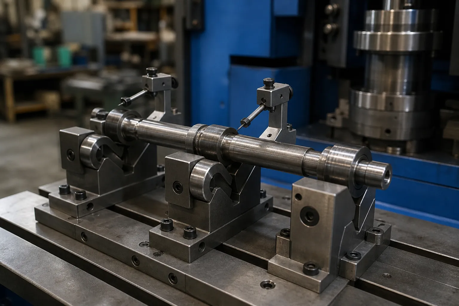
Four Jobs, One Fixture
A straightening fixture does four jobs at once, and every design decision trades between them:
- Localiza. Put the part in a repeatable position and orientation, so the machine measures the same part the same way every cycle and presses where the bend actually is.
- Sprijin. React the press force through structures stiff enough that the correction goes into the part, not into the fixture.
- Protect. Ensure nothing that touches the part – suporturi, nicovale, cleme, grippers – marks or brinells a functional surface.
- Let the measurement see the truth. Seating and support must not impose false geometry: a part clamped or rested in a way that bends it under its own weight measures a distortion that is not really in the part.
The fourth job is the one most often discovered late. A slender shaft resting on widely spaced hard supports sags between them; the same shaft on supports placed for convenience rather than mechanics can show runout that changes when it is lifted off the fixture. The fixture defines the gravity and constraint environment in which measurement happens – it is part of the measurement system, not just part of the tooling.
Datum Strategy: What the Fixture Locates Against
The fixture’s locating elements should carry the same datums the drawing and the downstream process use. For a stepped shaft, that usually means the bearing journals or centers; for parts with functional bores, the bore; for long components, the surfaces that define runout to the customer. Choosing convenience surfaces instead – a diameter that is easy to reach but not functionally relevant – builds a mismatch into every measurement that follows.
On stepped and feature-rich parts the choices get subtle, because a datum that is perfect for turning may not be the right one for straightening, where the part must rotate and be pressed. The reasoning process for selecting measuring datums on stepped shafts is laid out in our article on selectarea datelor de măsurare pentru arbori trepți, and the same logic applies to fixture locating elements: datum consistency between drawing, fixture and measurement is what makes the numbers mean something.
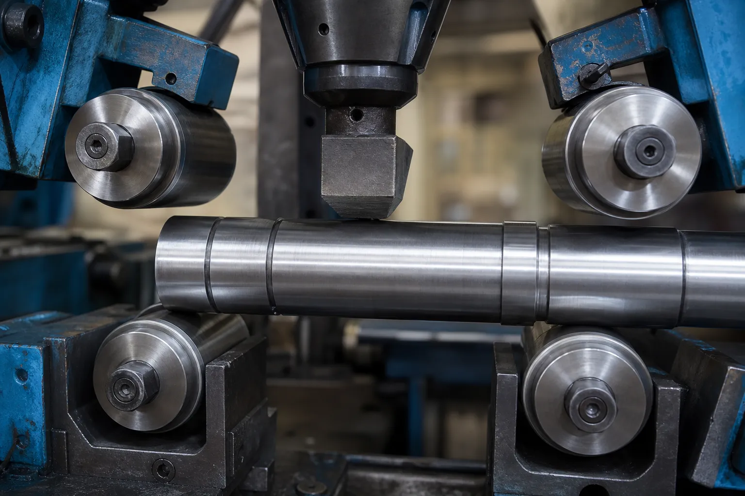
Support Span and the Force Path
Support placement is a mechanics decision before it is a tooling decision:
- Span versus stiffness. Pressing between widely spaced supports lowers the force needed for a given correction but risks unwanted bending elsewhere on a slender part; closely spaced supports concentrate correction but demand more force and higher fixture stiffness. The right span comes from the part’s geometry and the bend distribution, not from the stock fixture drawing.
- Support what you press. The force path from anvil through part to support should be direct and symmetric. A press point with no aligned support behind it sends load into whatever is nearby – including features that were never meant to take it.
- Fixture stiffness above part stiffness. Under correction load the softer structure absorbs the stroke. If the fixture or its base deflects measurably, the machine’s stroke control is partly correcting the fixture, cycle after cycle.
- Rotation without constraint. Straightening measurement rotates the part. Supports and centers must allow true rotation – role, knife edges or centers as the geometry dictates – or runout readings blend real bend with fixture-induced wobble.
These mechanics apply whether the correction is done on a press or with rollers; the comparison of îndreptarea prin presa versus îndreptarea cu role shows how the two routes distribute deformation differently, and the fixture follows the route chosen.
Contact Elements and Surface Protection
Everything that touches the part is a potential defect source. On hardened, ground or plated surfaces, contact elements need geometry and materials chosen against brinelling and marking: support rollers with correct profile rather than point contacts on a thin wall, anvils with relief where features must clear, and materials that are hard enough to last but not so localized that they indent the part. Clamping and holding forces belong on safe zones – the same zoning discipline used for grippers on automated lines. The full treatment of contact materials, roll profiles and protection practice is in our article on scule de protecție a suprafețelor în îndreptare.
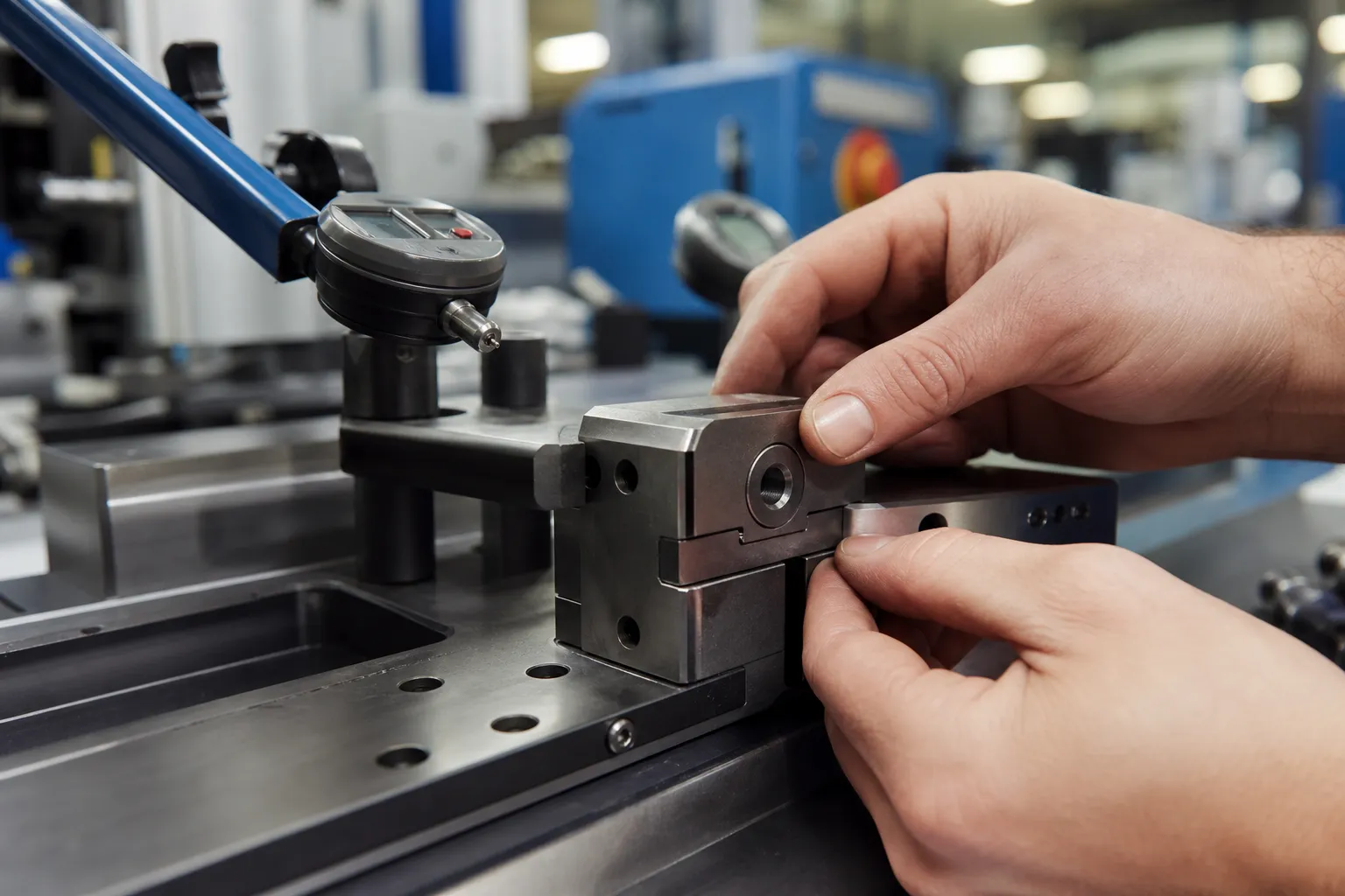
Fixture and Measurement as One System
The measure-press-remeasure loop of automatic straightening, așa cum este descris în cum funcționează îndreptarea automată a arborelui, only works if the fixture presents the part identically at every iteration. Sensor positions relate to supports: a probe reading near a support sees a constrained region, a probe mid-span sees free deflection, and point-press correction – the measure, sprijin, correct sequence covered in îndreptare prin presare punctuală – depends on probes and supports being where the process model assumes they are. Multipoint measurement concepts of the kind explained in Măsurarea arborelui multipunct LVDT formalize this relationship between measurement stations and the part’s support state.
The practical implication for fixture design: probe brackets, support carriages and press tooling are one kinematic system, and they should be designed, adjusted and documented together. A fixture that measures beautifully with one support configuration and is then run with supports moved for a different part family, without re-validating, is running on borrowed credibility.
Fixtures also age. Support rollers and centers wear, anvils take sets, locating pins loosen, and swarf works into adjustment mechanisms – and because the degradation is gradual, the first symptom is usually a slow drift in measured results rather than an obvious failure. Rolling fixture condition into the maintenance schedule with defined check intervals, and treating an unexplained change in measurement scatter as a fixture symptom until proven otherwise, keeps a validated setup validated for longer than hope alone will.
Changeover and Part Families
Most straightening fixtures serve more than one part. The changeover design determines whether a part switch takes minutes or an afternoon:
- Modular locating and support elements that swap as identified sets, with keyed or pinned positions so reassembly does not depend on operator skill.
- Stored recipes that carry press parameters, measurement configuration and the fixture setup associated with each part number, so the setup that was validated is the setup that runs.
- Setup verification steps – a master part, a reference measurement, or an explicit first-article check – that prove the changeover restored the validated state before production resumes.
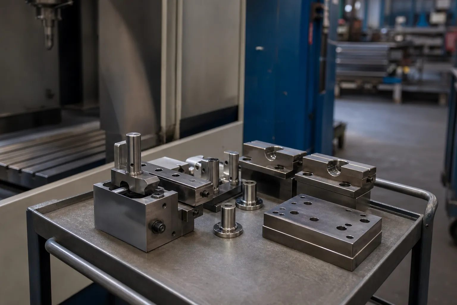
Proving a Fixture Before It Produces
A fixture is validated the same way the process is: with real parts and structured evidence. Sample-part testing of the kind described in testarea probei de îndreptare și acceptarea demonstrates that the fixture, machine and measurement combination corrects representative parts to tolerance repeatably. Machine acceptance checks – the gauges, workpieces and process-signature items in the straightening machine FAT checklist – should explicitly include fixture elements rather than treating tooling as an accessory. And when results drift or a new operator or automation change alters how parts are seated, the measurement-system analysis in Gage R&R pentru liniile de îndreptare is the tool that separates fixture-induced variation from part variation.
O notă despre imaginile din acest articol: sunt ilustrații de concept de inginerie create pentru acest articol, nu fotografii ale unei anumite linii de client, model de mașină, sau instalare, și sunt menite să sprijine doar discuția procesului.
Common Fixture Mistakes
- Locating on convenience surfaces instead of drawing datums, so parts pass on the machine and fail at the customer.
- Supports placed by habit – the same span for every part – regardless of bend location and part stiffness.
- Contact elements inherited from another part family and never re-profiled, producing marks that appear only on the new, softer or harder material.
- Fixture deflection assumed away. Under load, a compliant base or overhung support absorbs stroke and corrupts springback compensation.
- Changeover without re-verification. Recipes restored, supports moved, no master-part check – and the first hour of production is the experiment.
Întrebări frecvente
Should a straightening fixture clamp the part?
Generally no more than necessary. Straightening needs the part free to rotate for measurement and free to deflect under the press. Location is usually by centers, journals on rollers, or defined support stations; positive clamping, where used at all, belongs at safe zones with minimal force. Over-clamping a part that must be pressed is how fixtures fight the process.
How are fixture supports positioned for a new part?
From the part geometry and the measured bend distribution: supports aligned to the press points with spans chosen for the part’s stiffness, probes placed where runout matters per the drawing. The initial placement is then proven and refined during sample-part testing, and the validated positions are captured in the recipe so they are reproducible at every changeover.
Can one fixture serve very different parts?
With modular design, Da – within limits. The machine’s force and stroke envelope, the measurement range and the geometry of the parts set the boundaries. Widely different parts are usually better served by dedicated fixture sets that swap quickly than by one compromise fixture that serves none of them well.
How do we know when fixture wear is affecting results?
The signatures are gradual: measurement scatter that widens over weeks, correction iterations that creep upward for parts that used to pass quickly, or marks on surfaces that were previously clean. Any of these justifies pulling the fixture for inspection – checking roller profiles, anvil faces and locating element fit – before adjusting the process to compensate for a tooling problem.
Concluzie
Fixture design is where a straightening machine’s capability either reaches the part or gets lost on the way. Locate on the datums the drawing cares about, design the support span and force path for the actual part mechanics, protect every surface the fixture touches, keep measurement and support kinematically honest, and prove the whole setup with real parts before production counts on it. Teams that specify straightening equipment together with its tooling concept – rather than tooling as an afterthought – get processes that hold tolerance repeatably across part families and years. If you are developing a straightening process for a new part family, bring the drawings and tolerances into the tooling discussion from the start.