
Every straightening operation is a controlled contact event. A press anvil, a support roller, a chuck jaw or a transport V-block has to touch the workpiece in order to measure it, hold it and correct it. Whenever that contact is harder, sharper or dirtier than the part surface can tolerate, the result is a tooling mark — a permanent local deformation that stays on the part long after the bend has been corrected.
Tooling marks are one of the most common and most underestimated quality issues in shaft and tube straightening. The part leaves the machine geometrically correct but cosmetically and mechanically compromised. In this guide we break down where these marks come from, which ones actually matter, and how to prevent them without slowing the process down.
What Counts as a Tooling Mark
In straightening practice, “tooling marks” covers several distinct defects that are often lumped together:
- Press indentations (dimples) — shallow dents at the exact points where the press anvil contacted the workpiece during correction. They are the signature defect of point-press straightening done with excessive force or a mismatched anvil.
- Roller contact lines — longitudinal or spiral tracks left by support and drive rollers, most visible on polished or plated surfaces.
- Clamping marks — jaw impressions on the part ends or gripping sections, caused by excessive clamping force or hard jaw inserts.
- Handling scratches — random linear scratches from V-blocks, コンベア, bins and manual handling between operations.
- Fretting or burnishing patches — smears of transferred material or micro-adhesion damage where the part rotated against a support under load.
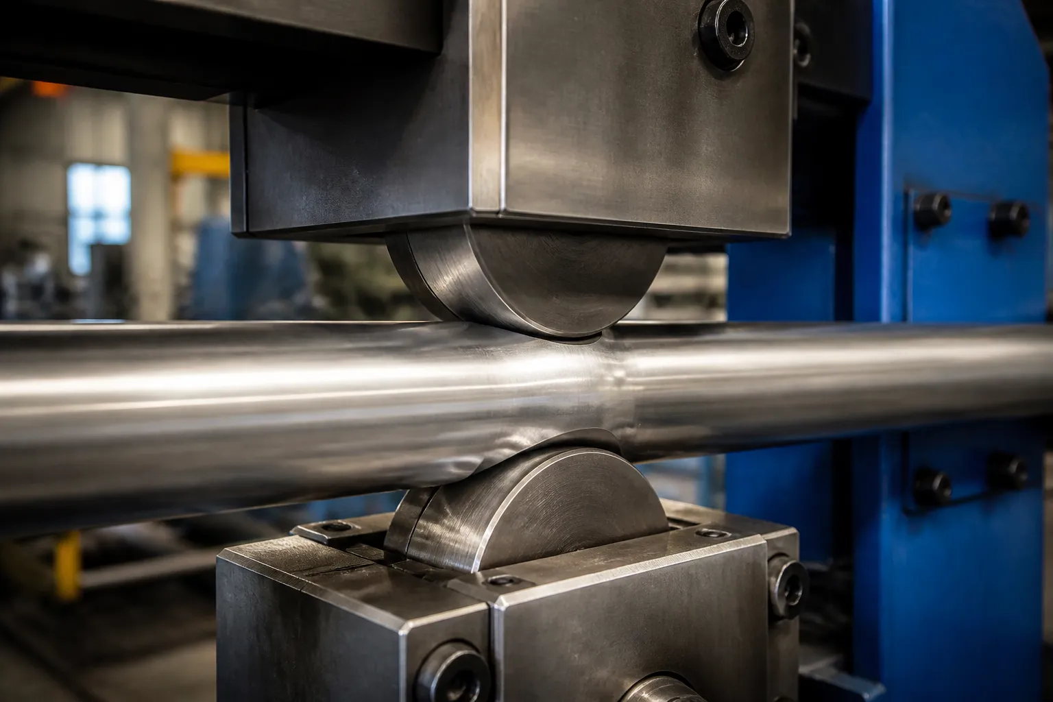
The first step of any prevention program is to stop treating these as one defect. Each type has a different root cause and a different fix.
Why Tooling Marks Matter More Than They Look
A shallow dent on a ground shaft looks cosmetic. Mechanically, it is anything but.
- Fatigue concentration. Any sharp transition in a shaft surface is a stress raiser. Rotating shafts live and die by their surface integrity; a mark with a hard edge can act as a fatigue initiation site in service, which is why rotating machinery specifications often cap allowable indentation depth or require blended repair.
- Destroyed surface finish. Parts that are ground, 磨かれた, plated or coated before straightening can lose the specified surface roughness at every contact point. If the drawing calls out Ra or Rz limits, a visible mark is usually already out of spec.
- Lost grinding stock. On parts that are straightened before final grinding, deep marks consume the machining allowance locally — the grinder has to remove the mark completely, or it survives into the finished part.
- Plating and coating defects. Indentations on parts destined for plating, nitriding or thermal spray act as traps and thickness disruptors, and are a classic rejection cause at final inspection.
- Customer perception. On visible or safety-relevant components — medical instruments, precision spindles, automotive shafts — tooling marks read as poor process control, even when the part is functionally acceptable.
There is also a downstream cost that rarely appears in the scrap report: marks discovered at final inspection force rework, regrinding or concession requests, all of which cost far more than preventing the mark in the first place.
根本的な原因 1: Contact Stress Above Local Yield
The fundamental mechanism behind every indentation mark is the same: the local contact pressure between the tooling and the workpiece exceeded the yield strength of the workpiece surface at that point. Whether that happens depends on four variables:
- Force per correction. A single aggressive press stroke delivers far more energy than the minimum needed to move the bend. Overdriving the press — a common habit when chasing a tight tolerance in one hit — is the single biggest cause of deep dimples.
- 接触形状. A sharp or narrow anvil radius concentrates force into a small area. A radius that is too large for the part, on the other hand, spreads the force so much that correction becomes ineffective and operators respond by pushing harder — creating marks anyway.
- Workpiece hardness and section. Thin-walled tubes, small-diameter pins and slender hardened shafts have less material supporting the contact zone. What a 60 mm solid bar tolerates easily can permanently mark a 6 mm hardened pin.
- Material pairing. Hard tool steel pressing on a soft or freshly heat-treated surface marks it; identical force against a harder or supported surface may leave nothing.
The practical conclusion: mark prevention is not only a tooling problem. It is a force control problem combined with a geometry matching problem. Machines that measure the bend and calculate the correction stroke keep the force near the minimum required, which is why they consistently mark parts less than manual pressing does. Our overview of the point-press straightening process covers how measured, incremental strokes limit both springback surprises and surface damage.
根本的な原因 2: Wrong or Worn Tooling Geometry
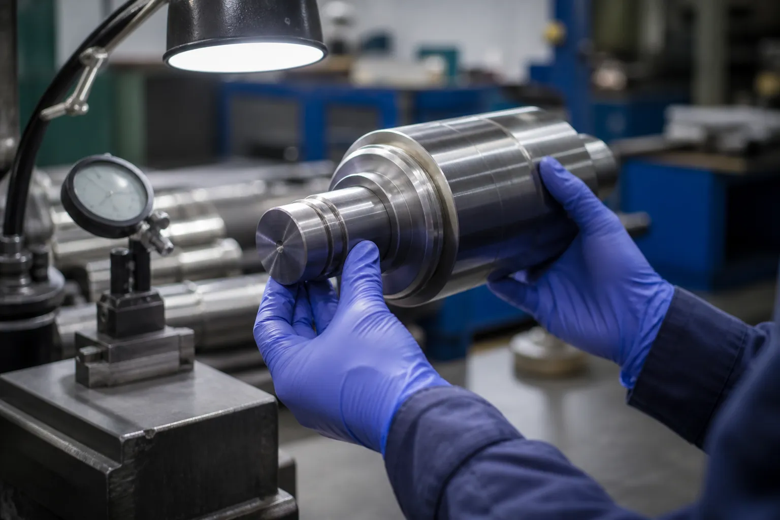
Tooling wears. An anvil that was matched to a part family five years ago may now be chipped, flattened or contaminated:
- Flattened anvil radii from years of pressing concentrate load on two edges instead of a smooth profile.
- Roller flats and dents print their own shape onto every part that passes over them. A roller with a flat spot produces a repeating mark — which is exactly the diagnostic clue: a periodic mark along the part almost always indicts a specific roller.
- Damaged or dirty V-blocks and supports. Swarf embedded in a support surface is crushed into the workpiece under load. Embedded particles also cause the deep, sharp scratches that are most dangerous for fatigue.
- Hardened jaw inserts on small parts. Serrated or ground-hard jaws grip effectively but imprint thin sections.
Tooling should be treated as a wear item with an inspection interval, exactly like a gauge. A quick profile check and cleaning of anvils and rollers at every changeover catches most geometry problems before they print onto a batch.
根本的な原因 3: Process and Setup Choices
Even with good tooling, several setup decisions drive marking:
- サポート間隔. Widely spaced supports allow the part to deflect under press force, so the contact zone absorbs deformation it was never meant to. Correct support spacing keeps the part rigid and limits local plastic flow at the anvil.
- Correcting on non-critical sections. Where the drawing allows it, correction points should be placed on sections that are machined later or hidden in assembly. Where correction must occur on a finished surface, tooling pressure must be managed accordingly.
- Rotation against supports under load. Parts measured while rotating between centers or on rollers generate sliding contact. Without clean, smooth supports, this produces burnishing and helical marks around the full circumference.
- Re-pressing the same spot. Repeated strokes at the same location accumulate local damage. Multi-point correction strategies distribute the work and reduce the depth of any single contact.
How measurement is set up matters too: if the part is measured under load and the setup applies measuring force through sharp tips or dirty supports, marks can be introduced before any correction has even started. The difference between loaded and released straightness measurement also determines how much contact the inspection itself imposes on the part.
Prevention Strategies That Work in Production
1. Match anvil geometry to the part
Anvil and support radii should be selected per part family, not per machine. The radius should be large enough to spread the force and small enough to keep correction effective, and it should be verified at changeover. For finished surfaces, ground and polished anvils — or padded inserts in bronze, polymer or soft steel — dramatically reduce visible marking.
2. Control the correction force
Use the smallest stroke that moves the bend, and prefer several small corrections over one large one. Automatic machines that calculate stroke from measured deflection and material behavior enforce this discipline; manual presses rely on operator skill, which varies across shifts.
3. Keep contact surfaces clean
Wipe anvils, rollers and supports at changeover and at defined intervals. Remove swarf before it can be pressed into parts. In high-volume cells, simple air wipe or brush stations at infeed pay for themselves quickly.
4. Protect finished surfaces deliberately
For plated, polished or ground parts, surface protection is a designed feature of the cell, 思いつきではない: padded supports, protective sleeves on rollers, controlled clamping force and clean handling trays. We cover this in detail in 矯正における表面保護工具, including roll geometry and contact stress management.
5. Handle parts like measurement artifacts
Most random scratches happen between operations, not inside the machine. Coated V-chutes, separated part trays and rules against stacking shafts directly on each other eliminate the majority of handling damage.
Which Marks Matter Most Depends on the Part
Prioritization is part of prevention. The same mark that is irrelevant on one part is a rejection on another, so the effort spent on protection should follow the part’s function:
- Rotating machinery components (spindles, モーターシャフト, axles): any sharp-edged mark on a finished journal or highly stressed section is a fatigue concern and deserves the strictest control.
- Medical and precision instruments (drills, mandrels, guidewires): cosmetic and cleanliness requirements make virtually every visible mark a rejection; padded tooling and clean handling are mandatory, not optional.
- Plated or coated parts: marks anywhere on the finished surface interfere with coating quality; protection effort concentrates on all contact points, including measurement supports.
- Parts with grinding stock remaining: shallow marks within the machining allowance are tolerable; the calculation is simply whether the mark depth plus straightness allowance still fits inside the stock. Deep dimples do not.
- Structural sections (バー, beams, tubes for static service): cosmetic marks are usually acceptable, and effort should focus on embedded debris and deep scratches only.
Writing this priority list into the part’s process plan — which surfaces are protected, which are allowed tooling contact, how deep a mark may be — converts an ambiguous “be careful with the surface” into instructions a machine operator and a tooling engineer can both act on.
Detecting Marks Before Your Customer Does
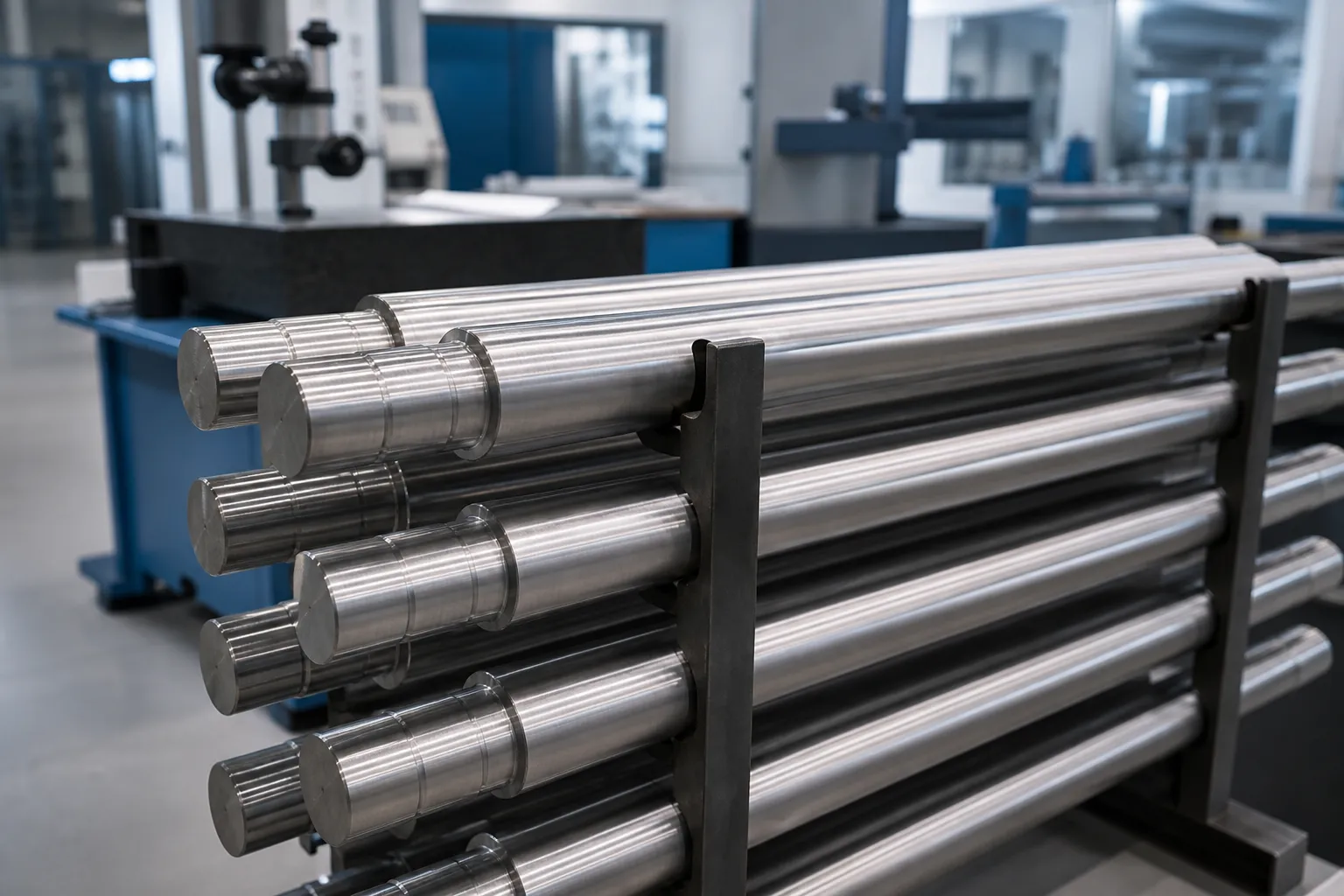
A workable inspection routine has three layers:
- Visual inspection under raking light at the machine, at defined intervals. This catches fresh marks while the setup that caused them is still identifiable.
- Surface roughness spot checks on marked locations where a drawing specifies Ra/Rz, using a portable roughness tester.
- Crack checking when marks are sharp or deep. A deep scratch or heavy indent on a hardened part deserves at least a close examination for micro-cracking; Magnetic particle or penetrant testing is appropriate for safety-relevant components. Our article on 自動矯正中の亀裂検出 explains the available signal- and inspection-based approaches.
Acceptance criteria should be written down — maximum mark depth, allowed locations, blending rules — and agreed with the customer where the application is critical. “No visible marks” is not a specification; it is an argument waiting to happen.
Key Takeaways
- Tooling marks are caused by local contact stress exceeding the workpiece surface’s yield strength — control force and geometry, not just tooling condition.
- Different mark types (dimples, roller lines, clamping marks, handling scratches) have different root causes and different fixes; classify before acting.
- Marks are not cosmetic: they are fatigue risks, surface-finish violations and plating defects.
- Prevention combines matched anvil geometry, minimal correction force, clean contact surfaces, deliberate surface protection and disciplined handling.
- Inspect under raking light at the machine, define acceptance criteria in writing, and escalate sharp marks to crack inspection.
If your parts carry tight surface requirements, mark prevention should be part of the machine specification from the start — tooling materials, force control and handling concept all need to match the part. We treat surface protection as a first-class selection criterion, and we are happy to review your part drawings and tolerance requirements before a machine is configured.