
Plusieurs lectures de déplacement peuvent transformer une inspection d'arbre long d'un seul pic en une carte d'erreurs. Cette valeur ne dépend pas seulement du capteur: géométrie de support, siège de référence, contact de sonde, rotation/indexation, synchronisation, les conditions environnementales et la règle de calcul affectent toutes ce qui est déclaré.

*Illustration du concept d'ingénierie. Ce n'est pas une spécification de capteur, système installé ou résultat de mesure vérifié.*
Définir la caractéristique avant de sélectionner les capteurs
Indiquez d'abord si la caractéristique d'acceptation est la rectitude de la ligne centrale., arc local, faux-rond par rapport à une donnée, écart de profil ou autre résultat contrôlé. Une trace de tension ou de déplacement d'un capteur ne constitue pas en soi une exigence du client.. Le plan d'inspection doit identifier les caractéristiques de référence, prend en charge, gares, orientations, portée, calcul, unités, limites et l'état dans lequel la pièce est acceptée.
| Élément | Question pour clôturer |
|---|---|
| Données | Quelles caractéristiques établissent l'axe ou la surface de référence? |
| Soutien | Est-ce qu'il reproduit l'état du client ou de la pièce libérée? |
| Chemin de la sonde | Les points de contact sont-ils des surfaces fonctionnelles et protégés contre les dommages? |
| Gares | Capturent-ils les zones de courbure et les transitions de fonctionnalités connues? |
| Rotation/indexation | Comment l'orientation est-elle préservée entre les lectures? |
| Calcul | Comment les lectures sont-elles converties en caractéristique contrôlée? |
Pour les contrôles de données, voir nettoyage du trou central de l'arbre et préparation des données et répétabilité du montage et positionnement des données.
Comment fonctionne un LVDT, et pourquoi sa physique est importante
Le transformateur différentiel variable linéaire gagne sa place sur les machines de production grâce à une courte liste de vertus physiques. A l'intérieur du logement, une bobine primaire est excitée par un courant alternatif, et deux bobines secondaires se trouvent de chaque côté; un noyau ferromagnétique, fixé à la pointe de la sonde par une fine tige de poussée, glisse le long de l'axe. Avec le noyau centré, les tensions induites dans les deux secondaires s'équilibrent; déplacer le noyau et les pointes du balancier proportionnellement au mouvement. L'électronique lit l'amplitude et la phase de ce déséquilibre et signale le déplacement.. Parce que le noyau ne touche jamais les bobines, il n'y a pas de friction ni d'usure à l'intérieur du capteur; car le couplage est inductif, la lecture est largement indifférente à la poussière, le brouillard d'huile et l'humidité qui aveuglent les capteurs optiques; et parce que la masse en mouvement est petite, la pointe peut suivre fidèlement les mouvements modérés de la surface. Les compromis sont également physiques: il nécessite un conditionnement du signal et un étalonnage par rapport à une référence, la sortie brute est relative plutôt qu’absolue, et la pointe de la sonde elle-même est un composant mécanique avec son propre état, histoire de force et d'usure.
Où les erreurs entrent entre la sonde et le numéro
Traiter la chaîne comme un seul système, comme l'exige la section ci-dessus, signifie connaître les portes spécifiques par lesquelles l'erreur entre. Dérive thermique: le corps du capteur, le luminaire et la pièce se dilatent et se contractent tous avec la température, et sur une machine qui chauffe pendant un quart de travail, un zéro du matin et une lecture de l'après-midi ne sont pas le même événement — d'où la vérification des références sur un maître à des intervalles définis par la procédure. Montage: une sonde sur une longue, le support non pris en charge est un porte-à-faux avec sa propre conformité, et la vibration ou la traction du câble déplace l'ensemble de l'ensemble par rapport à la pièce, impossible à distinguer du mouvement de la pièce dans les données. Dynamique: lorsque la pièce ou la sonde bouge pendant le balayage, la masse du stylet et la force de la pointe définissent une limite de vitesse au-delà de laquelle la pointe saute ou est en retard, écrire de fausses caractéristiques dans la trace. État des contacts: l'usure de la pointe aplatit le rayon prévu et change là où la lecture se trouve sur une surface incurvée. Aucun de ceux-ci n'est exotique; chacun est contrôlé par une procédure écrite – méthode zéro, intervalle de contrôle principal, vitesse de numérisation, inspection de la pointe - c'est précisément ce que le cadre de validation ci-dessus demande à la description du système de contenir.
Traitez la chaîne de mesure comme un seul système
Un LVDT peut convenir au déplacement relatif, mais le résultat mesuré inclut également le montage du capteur, déviation du luminaire, conditionnement du signal, timing, positionnement des pièces et comportement de l'opérateur ou de l'automatisation. Enregistrez chaque élément de la chaîne afin de pouvoir étudier un changement ultérieur dans le résultat..
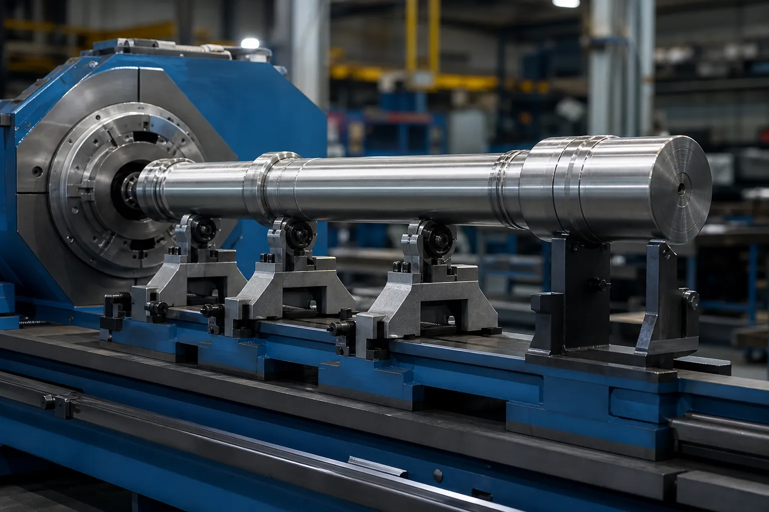
*Illustration du concept d'ingénierie. Rigidité du luminaire, la position du capteur et la protection nécessitent une ingénierie spécifique au projet.*
La procédure contrôlée doit couvrir l'identification des capteurs, contrôle de référence/maître, état de montage, protection des câbles, méthode zéro, orientation de l'échantillon, soutenir la propreté, paramètres d'acquisition de données et conservation des données. Une lecture répétée d'un appareil instable ne constitue pas une preuve de répétabilité.
Synchroniser l'emplacement, Orientation et lectures
Les données multipoints ne sont utiles que lorsque chaque valeur peut être attribuée à une position et une condition connues. Si la pièce tourne ou bouge, définir l'encodeur/index, coordonnées de la station, sens de déplacement, conditions de séjour ou d'échantillonnage, et que se passe-t-il si un signal manque. Le résultat doit préserver les données sources brutes ou traçables nécessaires à la reconstruction de la carte..
Évitez d'interpréter un pic localisé sans vérifier l'assise et le contact. Réinstaller les tests, une orientation inversée, le cas échéant, et des lectures de base répétées peuvent distinguer une caractéristique d'une pièce d'une fausse indication.
Choix du nombre et de l'emplacement des stations
Combien de stations, et où, c'est une question de géométrie avant d'être une question de budget. Les modes d'erreur des pièces minces sont lisses dans l'espace: un virage est une courbe basse fréquence, donc un nombre modeste de stations – placées là où la physique dit que l'information vit – la reconstruit bien, tout en doublant le nombre de positions non informatives, on achète un volume de données, pas de précision. Les positions informatives sont prévisibles: mi-portée entre les supports où un arc atteint son excursion; chaque transition de rigidité sur les pièces étagées, où les sommets aiment se cacher; immédiatement à côté des caractéristiques fonctionnelles dont la relation avec la donnée est importante; et les extrémités libres, qui ancre la carte. Le mode d'échec du placement clairsemé est l'aliasing dans sa forme pratique : un court pli entre deux stations ne contribue à aucune lecture propre., et une correction visant à ce que la carte reconstruite appuie au mauvais endroit. La manière honnête de réduire ce risque n'est pas une densité infinie mais une validation: cartographier un ensemble de pièces à haute densité une fois, confirmer que le poste de production reconstruit les mêmes pics et amplitudes, et documenter cette comparaison comme justification du plan de station.
Transformer la carte en décision de correction
La carte existe pour conduire l’action, et son vocabulaire d'action comporte trois entrées: où appuyer, dans quelle direction, et à quel point il est difficile d'attendre que la pièce réponde. La position et la direction du pic proviennent de la comparaison des stations autour du maximum; sur une pièce tournant entre stations, préserver l'indexation angulaire - la discipline de synchronisation ci-dessus - est ce qui convertit les lectures séparées en un vecteur, pas un tas de grandeurs. La réponse attendue vient de l'histoire de rigidité que la carte raconte déjà: un pic sur une section épaisse nécessite un plan de correction différent de celui de même amplitude sur une section fine, et les pics aux transitions de rigidité méritent le respect décrit pour séparer le virage de la rondeur et les effets de configuration avant que toute presse ne suive. Ce que la carte ne doit pas faire, c'est déclencher une correction sur des signaux non vérifiés: une lecture localisée qui n'a pas survécu à un contrôle de réinstallation est une hypothèse, pas un pic. Ce garde-corps – carte, vérifier, alors corrige, avec une mesure à l'état relâché fermant la boucle - est la même séquence qui fait redressage automatique de l'arbre converger en quelques coups au lieu de plusieurs.
Corréler avec l'acceptation des pièces lancées
La mesure pendant le serrage ou la correction peut être utile pour le contrôle du processus, mais cela ne prouve pas automatiquement que l'arbre libéré répond aux exigences. Comparez la méthode en ligne avec une méthode approuvée des pièces libérées sur des échantillons représentatifs dans une variation normale. Voir mesure de rectitude en charge ou en libération pour la limite.
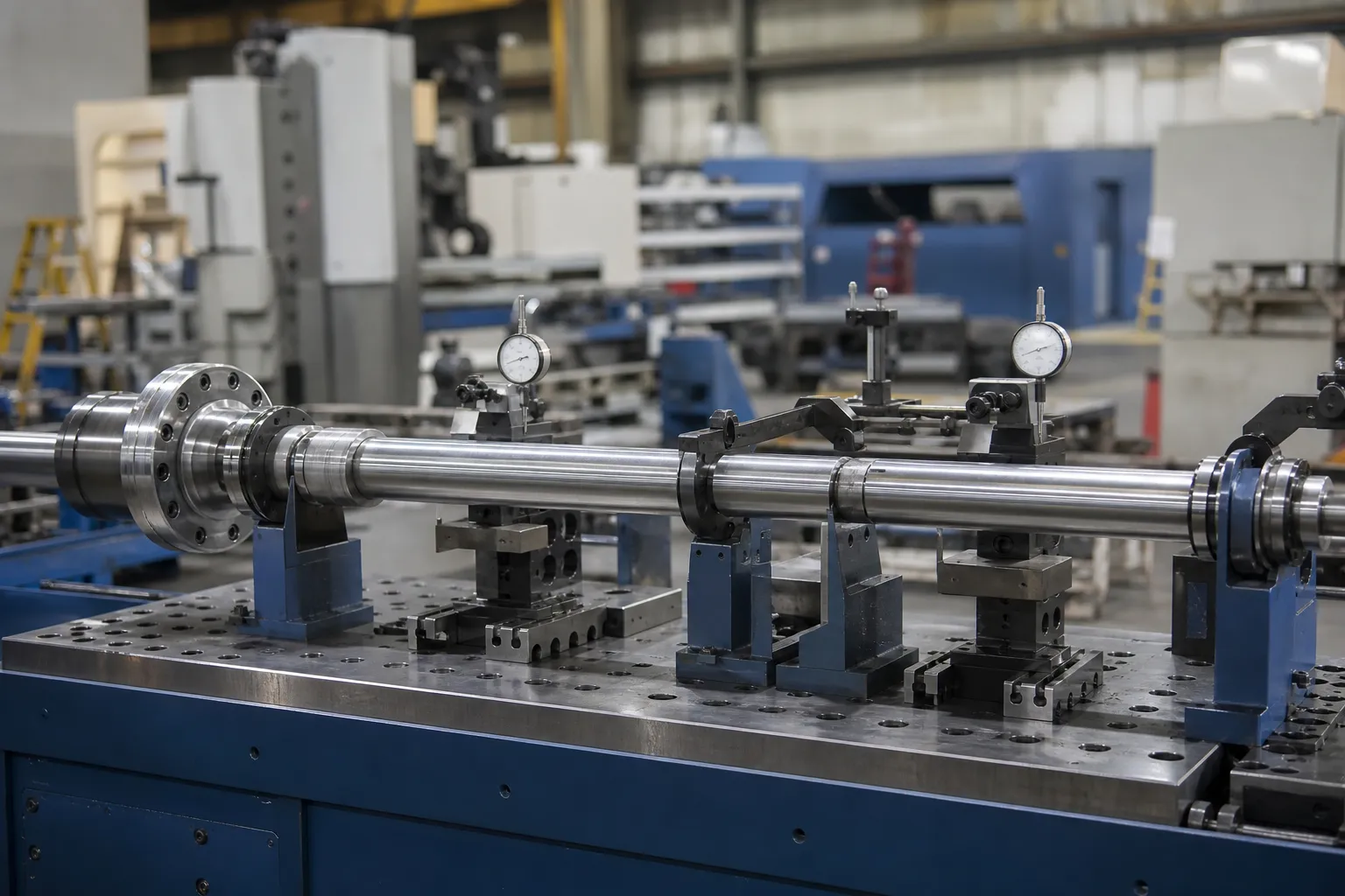
*Illustration du concept d'ingénierie. La méthode de référence, les supports et le calcul d’acceptation doivent être contrôlés par le plan qualité approuvé.*
Un plan de corrélation doit définir des échantillons appariés, comparaison aveugle lorsque cela est possible, équivalence donnée/support, état d'étalonnage, examen des biais, examen de répétabilité/reproductibilité, différence autorisée, règles d'escalade et de contrôle des modifications. Se référer à corrélation entre la jauge de la machine et la jauge du client et jauge R&R pour redresser les lignes.
Entrées nécessaires pour une étude de mesure
Fournir le dessin et la définition des caractéristiques, méthode d'inspection existante, géométrie de la pièce et fonctions de référence, étape matière/fabrication, emplacements de courbure prévus, échantillon de population, contraintes environnementales, enregistrement de données souhaité et méthode d'acceptation par le client. Utilisez le test d'échantillon de redressage et guide d'acceptation établir le dossier du procès, alors contacter StraighteningTech pour une discussion sur l'application.
Validation requise avant une réclamation système
Toute demande de mesure multipoint nécessite une configuration définie de la sonde et des données., références calibrées, lectures répétées ou réinstallées sur des pièces représentatives, et corrélation des indicateurs client. Une capacité générique de machine n'est pas un résultat vérifié.
FAQ
L'ajout de stations de mesure supplémentaires améliore-t-il automatiquement la précision?
Non. Stations placées là où la géométrie contient des informations – pics à mi-portée, transitions de rigidité, caractéristiques fonctionnelles, se termine — améliorer la carte. Les stations ajoutées ailleurs augmentent le volume de données et les coûts tout en laissant la reconstruction essentiellement inchangée. Valider une fois l'ensemble choisi par rapport à une carte dense et documenter la comparaison.
Pourquoi les lectures LVDT dérivent-elles au cours d'un changement de production?
Le plus souvent thermique: capteur, le luminaire et la pièce se dilatent à des rythmes différents à mesure que la cellule se réchauffe, décaler le zéro. Les causes mécaniques viennent ensuite : conformité des tranches, traction par câble, usure de la pointe. Le contrôle est procédural: une méthode de zéro définie et des contrôles de référence à intervalles définis, tout changement au-delà des limites de la procédure déclenchant une enquête plutôt qu’une remise à zéro silencieuse.
Les données LVDT multipoints peuvent-elles remplacer l'inspection finale?
Uniquement par corrélation. Les données multipoints en cours de processus pilotent la boucle de correction; la décision d'acceptation appartient à la méthode d'état validé que le client reconnaît. Lorsque les deux ont une corrélation documentée sur des pièces représentatives, la méthode en ligne gagne du terrain - en attendant, il s'agit de contrôle de processus, ne pas libérer.
Ressources StraighteningTech connexes
Voir comment fonctionne le redressage automatique de l'arbre, Test d'échantillon de redressage et acceptation et rectitude de l'arbre vs faux-rond vs TIR pour les limites de contrôle génériques qui s'appliquent avant toute revendication de capacité sur Mesure d'arbre multipoint LVDT.
La mesure multipoint est payante au moment de l'acceptation – associez le Liste de contrôle FAT avec le DG&Guide d'acceptation de rectitude T pour convenir de la méthode de mesure et de l'interprétation des tolérances en un seul passage.