
Un arbre de broche de machine-outil n’est pas simplement un arbre rond de précision. Ses sièges de roulement avant et arrière établissent l'axe de support rotatif, tandis que l'interface de l'outil, face de jauge, les caractéristiques d'entraînement et les passages internes de la barre d'attelage ou du liquide de refroidissement doivent rester fonctionnellement liés à cet axe. Le même arbre peut également contenir de fines sections creuses, trous transversaux, clés, cannelures, fils de discussion, corrections d'équilibre et surfaces localement durcies.
Pour cette raison, une solution de redressage de broche de machine-outil doit commencer par une décision de faisabilité: la pièce à usiner est-elle un arbre de broche nu à une étape de fabrication contrôlable, ou est-ce déjà une cartouche de broche finie avec roulements, moteur et système de serrage installés? Un redressage sous pression contrôlée peut être envisagé pour un arbre nu approprié avec des zones de traitement approuvées.. Un ensemble de broche complet nécessite normalement une évaluation de la broche, démontage et diagnostic au niveau des composants avant toute décision de correction.

*Illustration du concept d'ingénierie: une ébauche d'arbre de broche brute et brute supportée pour une correction contrôlée sur un terrain de processus approuvé. Ce n'est pas une photographie du site client. Outillage réel, emplacements d'assistance, les limites de charge et la taille de la machine nécessitent des dessins et des tests sur échantillons représentatifs.*
Définissez d’abord ce qui est à redresser
Le mot « broche » est utilisé pour plusieurs produits différents. Ils ne partagent pas un seul itinéraire de redressement.
| Pièce à usiner | Contenu typique | Décision de redressement de la pression |
|---|---|---|
| Arbre de broche nu ou plume | Sièges de roulement, interface outil, alésage, côté entraînement | Potentiellement réalisable après la date, examen du matériel et des zones de contact |
| Ebauche de broche grossièrement usinée | Surépaisseur d'usinage et zones de traitement désignées | Généralement la meilleure étape pour une étude sur échantillon contrôlé |
| Arbre de broche rectifié | Sièges fonctionnels, cône, faces et finition de surface | Très restreint; contact protégé et réinspection complète requise |
| Cartouche de broche complète | Arbre, roulements, système de précharge, logement, joints et timon | Ne pas traiter comme un arbre nu; évaluer et démonter d'abord |
| Ensemble rotor de broche moteur | Ensemble arbre de broche et rotor, aimants ou enroulements | Nécessite un rotor, électrique, ingénierie thermique et d'équilibre |
| Porte-outil ou tonnelle | Interface d'outillage amovible séparée | Une norme de pièce et d'acceptation différente |
| Mandrin de tour ou nez de broche porte-pièce | Interface de serrage et fonctionnalités d'assemblage | Nécessite un diagnostic spécifique à l'interface, ce n'est pas une recette générique |
Cette page couvre le arbre de broche de machine-outil nu. Il ne prétend pas qu'une électrobroche assemblée, la cartouche ou le jeu de roulements peuvent être placés dans une presse et corrigés en toute sécurité.
Identifiez la famille de broches et l'interface
La proposition doit identifier la construction réelle de la broche plutôt que d'utiliser uniquement la longueur totale et le diamètre maximum.:
- fraisage, centre d'usinage, tournant, broche de meulage ou à usage spécial;
- entraîné par courroie, à engrenages, architecture à entraînement direct ou motorisée;
- arbre plein, arbre creux, construction en forme de plume ou de manchon;
- HSK, SK/cône raide, CFP, Morse, cône exclusif, cône externe, interface de montage sur mandrin ou d'ajustement-alésage;
- système de contact à contact unique ou face et cône;
- disposition des roulements avant et arrière, séquence roulement-siège et concept de précharge;
- alésage de la barre d'attelage, passage de liquide de refroidissement, voies aériennes, trous de lubrification et perçages transversaux;
- poulie intégrée, engrenage, cannelure, rainure de clavette, piste d'encodeur, labyrinthe ou terre de phoques;
- carburé, nitruré, trempé par induction, régions revêtues ou durcies sélectivement;
- pièce de nouvelle production, retour de réparation ou composant de remise à neuf de la broche.
GMN décrit des interfaces d'outils automatiques telles que HSK, SK et PSC en tant que systèmes impliquant l'interface de l'outil et la face de contact plate. La leçon de conception transférable est que l'alésage conique interne ou d'ajustement et la face de jauge sont des caractéristiques fonctionnelles., surfaces de presse peu pratiques.
Geler l’étape de fabrication ou de réparation
Après traitement thermique et usinage grossier
La géométrie de l'arbre et l'état du matériau sont établis tandis que le stock de meulage de finition peut rester. Si centres stables, des sièges de référence et des terrains de processus approuvés existent, c'est normalement l'étape la plus contrôlable pour une étude de faisabilité.
Avant le meulage de finition du siège de roulement et de l'interface de l'outil
Le redressage peut réduire le stock qui serait autrement consommé tout en générant l'axe roulement-siège final et l'interface outil. Le plan de processus doit toujours conserver suffisamment de surépaisseur de meulage pour chaque fonctionnalité.
Après avoir terminé le meulage
Sièges de roulement, cônes, faces de jauge, les zones de joint et les épaulements portent déjà une géométrie fonctionnelle et une finition de surface. Le support ou le contact presse peuvent avoir un impact, les brunir ou les déformer. Toute correction à ce stade nécessite un outillage protégé, une carte de charge restreinte et une mesure post-traitement complète.
Après équilibrage
Le redressage peut changer la géométrie, contrainte matérielle et relation entre les plans de correction. Il ne faut pas supposer que l’arbre conserve son état d’équilibre précédent.. L'équilibrage final doit suivre la dernière opération qui modifie matériellement la géométrie ou la masse..
Après l'assemblage du roulement ou du moteur
N'appliquez pas de recette de lissage à tige nue. Précharge du roulement, état du chemin de roulement, ajuster, position du rotor, force de serrage, la croissance thermique et l'alignement du boîtier contribuent tous au comportement de la broche. Acheminer l’assemblage vers l’évaluation de la broche et le démontage contrôlé.
Service ou retour en cas d'accident
Une broche écrasée peut contenir des roulements brinellés, dommages au cône, fretting interface-outil, un cône tiré ou en cloche, sections fissurées, composants du timon endommagés, élasticité locale ou détresse thermique. Le faux-rond statique à basse vitesse ne peut à lui seul classer ces conditions comme une courbure d'arbre corrigible..
| Scène | Preuves disponibles | Risque principal | Itinéraire par défaut |
|---|---|---|---|
| Blanc brut | Données de processus et cartographie des stocks | Le brut de surface peut apparaître comme un pli | Établir des données stables et corriger les échantillons-tests |
| Traité thermiquement, pré-broyage | L'état des matériaux et la géométrie fonctionnelle sont plus clairs | Risque élevé de retour élastique ou de fissure | Valider l'enveloppe de force/déplacement et le stock de meulage |
| Arbre rectifié | Les sièges fonctionnels et l'interface peuvent être mesurés | Marquage de surface et dommages de forme | Correction protégée restreinte ou rebroyage/rejet |
| Arbre équilibré | L'enregistrement du solde existe | Le solde précédent peut devenir invalide | Corriger la géométrie d'abord, puis rééquilibrer |
| Cartouche complète | Des données de tests fonctionnels peuvent exister | Roulement caché, précharger, rotor et effets thermiques | Évaluer, démonter et diagnostiquer les composants |
| Crash/retour de service | L'historique des échecs peut être connu | Les dommages peuvent être confondus avec une courbure | Itinéraire d’inspection et de réparation/rejet avant correction |
Définir la chaîne de données fonctionnelle
La solution doit indiquer quelles fonctionnalités définissent la pièce et lesquelles ne sont que des références de processus temporaires..
- Dates de dessin définir les relations géométriques spécifiées.
- Sièges de roulement avant et arrière définir l'axe de support d'arbre installé.
- Cône ou alésage d'interface outil localise l'outil ou le système de serrage.
- Face de jauge ou face de nez de broche contrôle l'assise axiale et le faux-rond de la face.
- Centres ou journaux de processus peut soutenir le virage, meulage ou redressage.
- Conduire, caractéristiques du codeur et du joint doit rester lié à l'axe du roulement.
- Journaux d'équilibrage et plans de correction définir une configuration de correction de masse.
- La broche et la structure de la machine assemblées définir la condition finale de fonctionnement.
Ces références peuvent être liées, mais ils ne sont pas interchangeables. Des centres précis ne prouvent pas que deux sièges de roulement sont coaxiaux. Un faible faux-rond au niveau d'un tourillon externe ne prouve pas que le cône interne de l'outil est correctement lié à l'axe du roulement.. Un bon résultat d’équilibre ne prouve pas la rectitude géométrique.
Rectitude séparée, S'épuiser, Performances de forme et de broche
Une seule lecture d'indicateur peut combiner plusieurs sources d'erreurs. Le plan de dessin et de réception peut contrôler séparément:
- rectitude de l'axe du corps de l'arbre;
- faux-rond de chaque siège de roulement;
- coaxialité entre les axes des portées de roulement avant et arrière;
- faux-rond interne du cône de l'outil par rapport à l'axe du roulement;
- battement axial du nez de broche ou de la face de jauge;
- rondeur et cylindricité du tourillon;
- angle de conicité, modèle de contact, cloche ou usure locale;
- épaule, fil, cannelure, voile de poulie ou de piste d'encodeur;
- déséquilibre statique et couple;
- faux-rond non répétable, état des roulements et vibrations de la broche assemblée;
- déplacement de la pointe de l'outil, force de serrage et croissance thermique.
Utilisez le Rectitude de l'arbre, faux-rond et guide TIR pour séparer la géométrie des axes de l'indication de rotation. Le redressage peut potentiellement modifier une relation globale de courbure ou d'axe.. Il ne corrige pas automatiquement la rondeur locale, dommages au cône, dommages au visage, défauts de roulement, déséquilibrer, perte de force de serrage ou instabilité thermique.
Mesurez plusieurs pistes fonctionnelles avant d’appliquer une force
Le guidage de précision par roulements Schaeffler et NTN traite la rondeur du siège d'arbre, cylindricité, coaxialité et faux-rond en fonction de la précision de fonctionnement de la broche. GMN identifie les interfaces des outils, adapter les alésages et les fonctions de surveillance de la broche en tant que fonctionnalités de broche distinctes. L'implication pratique est un plan de mesure multipiste.
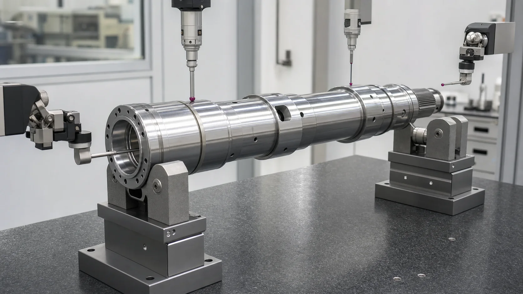
*Illustration du concept d'ingénierie: inspection multivoie des tourillons de siège de roulement, l'interface interne de l'outil et la face de la jauge avant une décision de correction. Type de sonde, espacement des stations, L'outillage principal et l'incertitude admissible suivent le plan de dessin et de corrélation de jauge.*
| Piste de mesure | Question principale | Risque typique de mauvaise classification |
|---|---|---|
| Siège de roulement avant | Où est l'axe de support avant? | Un lobage ou des dommages locaux peuvent ressembler à une excentricité |
| Siège de roulement arrière | Est-ce coaxial avec le siège avant? | L'erreur de support peut être interprétée comme une courbure de l'arbre |
| Terrains de puits intermédiaires | Quelle est la forme globale du pli? | La variation du diamètre peut biaiser une sonde de contact |
| Cône d'outil interne ou alésage d'ajustement | L'axe de l'outil est-il lié à l'axe du roulement? | Les dommages causés par la forme conique peuvent apparaître comme un pur voile |
| Face de jauge ou nez de broche | L'assise axiale est-elle carrée par rapport à l'axe? | Bavures, les frottements et les bosses locales peuvent dominer la lecture |
| Alésage traversant/timon | La distribution murale est-elle structurellement sûre? | Une paroi mince cachée ou des trous transversaux peuvent invalider un chemin de charge |
| Caractéristiques du variateur/encodeur/joint | Les composants connectés fonctionneront-ils correctement? | Une erreur de forme de fonctionnalité peut être confondue avec un virage global |
| Plans d'équilibre | L'axe de masse est-il acceptable? | L'équilibre ne peut pas identifier la forme géométrique à lui seul |
L'arbre doit tourner dans des positions angulaires définies, avec répétabilité vérifiée avant correction. La trace à l'état relâché (et non la lecture déviée sous la presse) détermine le résultat géométrique.
Erreur de prise en charge du contrôle, Affaissement et température
La courbe mesurée dépend de la façon dont l'arbre de broche est supporté. Centres, Blocs en V, rouleaux de journal, les supports équivalents aux appuis et les appuis finaux ne créent pas de conditions limites identiques.
La recette de mesure doit définir:
- fonctionnalités de support, coordonnées axiales et profils de contact;
- si les revues ou centres de référence sont qualifiés avant utilisation;
- orientation de l'arbre et index angulaire;
- traitement contre l'affaissement par gravité pour les arbres longs ou creux;
- force du capteur, espacement sans contact et espacement des stations;
- filtrage et masques de fonctionnalités autour des trous, touches et interruptions;
- température des pièces et temps de stabilisation;
- maître, jauge R&R et corrélation avec la meuleuse ou la jauge client;
- réévaluation entièrement déchargée après chaque étape de correction.
Le comportement thermique nécessite une décision distincte. Les concepts de broches Schaeffler et le matériel d'évaluation des broches SKF distinguent la croissance thermique, déplacement de l'arbre, état des roulements, faux-rond du nez de l'outil et comportement lié aux vibrations. Un arbre qui réussit un contrôle statique à froid mais bouge pendant l'échauffement peut avoir un roulement, précharger, logement, problème de rotor ou de symétrie thermique. La correction aveugle de la pression à froid ne remplace pas le diagnostic de l'état de fonctionnement.
Créez un contact protégé et une carte sans presse
Zones sans pression par défaut
- cône d'outil interne ou externe;
- face de jauge, nez de broche et alésages de précision;
- sièges de roulement et faces de butée de roulement finis;
- joint, pistes de labyrinthe et d'encodeur;
- épaules, congés et transitions de section nettes;
- fils de discussion, cannelures, clés, rainures de clavette et dents d'engrenage;
- trous transversaux, trous de lubrification et passages de liquide de refroidissement;
- fentes pour timon et fines sections creuses;
- exercice d'équilibre, emplacements de broyeur à équilibre ou de poids ajouté;
- trempé par induction, carburé, nitruré, zones enduites ou réparées;
- soupçonné d'être fissuré, brûlé, régions frettées ou endommagées par un impact.
Zones de contact potentiellement approuvées
- le processus cylindrique grossièrement usiné atterrit avec un stock suffisant;
- colliers de support sacrificiels ou extensions de processus amovibles;
- sections cylindriques larges vérifiées par dessin et examen de l'épaisseur des parois;
- interfaces d'outils spécialement conçues et approuvées par le concepteur de broches.
L’approbation des contacts est locale et spécifique à l’étape. Un diamètre sûr sur ébauche brute peut être interdit après meulage ou trempe.
Protéger l'alésage traversant et la section transversale
De nombreux arbres de broche sont creux pour une barre d'attelage, livraison de liquide de refroidissement, fonction de purge d'air ou de maintien de la pièce. Le diamètre extérieur seul ne suffit pas à dimensionner la charge de correction.
L'examen de faisabilité devrait inclure:
- diamètre d'alésage et épaisseur de paroi par station axiale;
- transitions coniques et lamées;
- trous transversaux, machines à sous, ports et passages qui se croisent;
- filetages internes et caractéristiques de la barre de traction;
- profondeur du traitement thermique et gradient de dureté;
- ajustements rétractables, manches, fiches ou composants collés;
- ovalité autorisée et alignement de l'alésage après correction.
Une charge en trois points qui corrige la ligne médiane externe peut toujours ovaliser l'alésage, déformer le cône ou concentrer la contrainte autour d'un trou transversal. Outillage à large rayon, les portées de sécurité et les limites de force/déplacement doivent être validées sur des échantillons représentatifs. Pour sections fines, voir Redressage de tubes à paroi mince sans effondrement pour le principe général selon lequel la correction de la ligne médiane et la préservation de la section transversale doivent être contrôlées ensemble.
Décidez si le lissage est le bon processus
| État observé | Itinéraire de processus probable |
|---|---|
| Courbure globale sur un puits nu avec des terrains de processus sécurisés | Test de faisabilité du redressage contrôlé |
| Les sièges de roulement sont localement ronds ou coniques | Affûtage, reprise, placage/réparation ou rejet |
| Le cône de l'outil présente des frottements, dommages en forme de cloche ou de motif de contact | Meulage/réparation d'interface et vérification de jauge |
| La face de la jauge est localement endommagée | Réparation ou réaffûtage du visage, pas de correction d'arbre aveugle |
| La broche complète présente des vibrations ou une augmentation de température | Évaluation de la broche: roulements, précharger, équilibre, résonance, force de serrage et condition thermique |
| L'arbre est droit mais l'équilibre échoue | Équilibrage dynamique dans des plans spécifiés |
| L'arc thermique n'apparaît que pendant le fonctionnement | Enquête thermique et d'assemblage |
| Aucun point de chargement sécurisé n'existe entre les fonctionnalités protégées | Étape du processus de refonte, machine/broyage, ou rejeter |
| Fissure, brûler, un pli local ou de graves dommages causés par un accident sont suspectés | Évaluation CND/métallurgique et voie de réparation/rejet |
Cette limite de décision empêche la machine à dresser d'être utilisée comme outil de réparation universel pour chaque symptôme de broche..
Lissage, Le meulage et l’équilibrage sont des portes différentes
Le lissage peut potentiellement résoudre
- une courbure élasto-plastique globale dans un arbre nu approuvé;
- relation axe roulement-siège avant le meulage final;
- déséquilibre excessif du stock causé par un flan brut plié;
- géométrie intermédiaire après traitement thermique.
Le meulage ou l’usinage peuvent résoudre
- diamètre final du siège du roulement, rondeur et cylindricité;
- forme de cône d'outil et géométrie de contact;
- géométrie de la face de jauge;
- excentricité limitée dans le stock disponible;
- état de surface et caractéristiques fonctionnelles locales.
L’équilibrage peut répondre
- déséquilibre statique et de couple dans des plans de correction définis;
- erreur d'axe de masse après les opérations de géométrie finale et de changement de masse.
Schenck identifie les arbres de broche comme des pièces d'équilibrage. Cela prend en charge une porte de solde final distincte; cela ne veut pas dire que l'équilibrage corrige un axe géométrique courbé. Si le redressage ou le meulage suit l'équilibrage, le solde doit être revérifié.
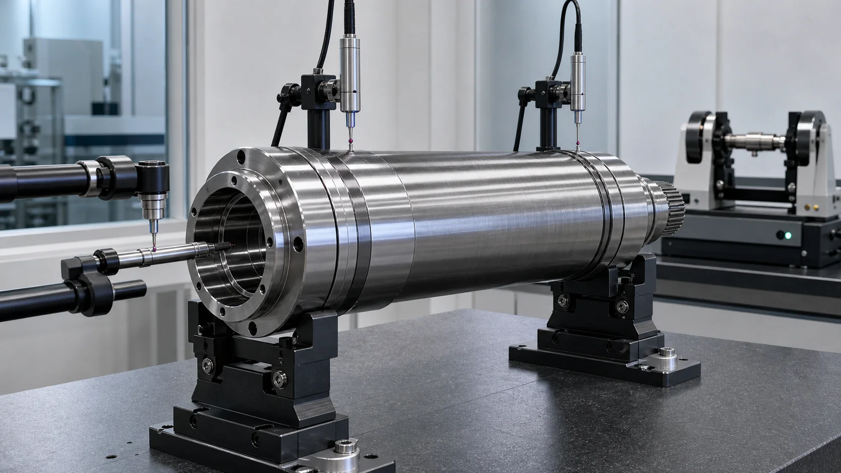
*Illustration du concept d'ingénierie: faux-rond de l'arbre final, la géométrie de l'interface outil et l'équilibre dynamique sont des portes d'acceptation distinctes. Passer une porte ne prouve pas les autres.*
Processus de redressage d’arbre de broche en boucle fermée
1. Identifiez la pièce exacte et l'étape du processus
Sélectionnez la recette validée à partir du numéro de pièce, révision du dessin, famille de broches, matériel, traitement thermique, dureté, géométrie de l'alésage et étape de fabrication ou de réparation.
2. Inspecter avant le chargement
Nettoyer la référence et les surfaces de contact autorisées. Inspecter les sièges de roulement, cône, face de jauge, alésage, trous, rainures de clavette, transitions et régions sensibles aux crashs. Acheminer les dommages suspectés vers l'inspection requise avant d'appliquer la force.
3. Établir la configuration de référence
Supporter l'arbre sur des centres agréés, tourillons de processus ou fixations équivalentes à des sièges de roulement. Vérifier les sièges, liberté axiale et répétabilité de référence.
4. Mesurez la carte fonctionnelle complète
Faites pivoter la pièce et enregistrez le comportement du siège de roulement avant/arrière, terrains d'arbre intermédiaire, faux-rond de l'interface outil, faux-rond de la face de jauge et caractéristiques d'entraînement pertinentes. Masquer les discontinuités et vérifier les mesures répétées.
5. Classer l'écart
Séparer le virage global du formulaire de journal local, dommages au cône, dommages au visage, erreur de support, déformation de l'alésage, comportement thermique et balourd. Corrigez uniquement la classe d'écart couverte par la recette validée.
6. Sélectionnez une plage de correction sûre
Choisissez des terrains de processus approuvés et un outillage étendu. Confirmez que le chemin de charge évite les sièges finis, cône, épaules, paroi mince, trous transversaux et transitions durcies.
7. Appliquer une force contrôlée
Utiliser une durée de support validée, coordonnée de correction, plafond de force, modèle à déplacement de plafond et à ressort. Surveillez la réponse complète force-déplacement et arrêtez-vous en cas de raideur anormale, comportement de glissement ou de capteur.
8. Décharger complètement et remesurer
Juger l'arbre uniquement à l'état libéré. Reconstruisez toutes les pistes de mesure pertinentes car une correction locale peut modifier les relations de plusieurs axes.
9. Inspecter et acheminer en aval
Effectuer le crack requis, surface, contrôles d'alésage ou de dureté. Acheminer la pièce à terminer le meulage, vérification de la conicité/face, nettoyage, équilibrage et assemblage de broches tels que définis par le plan de processus.
10. Enregistrez le résultat
Stocker l'identité de la pièce, révision de la recette, cartes entrantes et sortantes, coordonnées de correction, courbes force-déplacement, alarmes, traçabilité de l'opérateur/du lot et disposition finale si nécessaire.
Configuration de cellule de lissage proposée
Une cellule à arbre de broche spécifique au projet peut inclure:
- unité de correction électromécanique ou hydraulique dimensionnée à partir d'un échantillon de données de force;
- supports ou centres réglables adaptés aux références approuvées;
- rotation servo et indexation angulaire;
- plusieurs capteurs de faux-rond sans contact ou à faible force;
- Interface d'outil dédiée et station de mesure de face de jauge;
- larges patins de presse interchangeables et outillage de support protégé;
- surveillance des forces et des déplacements;
- Compensation automatique du retour élastique et réévaluation à l'état relâché;
- contrôle des recettes, verrouillage de révision de dessin et identification des pièces;
- interfaces avec le meulage, enregistrements d’équilibrage et de qualité;
- gardes, aide au chargement et dépannage adapté à la masse de la pièce et à l'état de sa surface.
Le Comment fonctionne le redressage automatique de l’arbre le guide explique la boucle fermée générale. Le projet de broche nécessite toujours sa propre chaîne de données, carte de contact et logique d'acceptation.
Exemple de plan de test et d'acceptation
Les échantillons représentatifs doivent couvrir:
- longueur d'arbre minimale et maximale, diamètre et masse;
- plus petite épaisseur de paroi et plus grand alésage traversant;
- chaque famille d'interfaces d'outils et de nez de broche;
- matériel, traitements thermiques et duretés extrêmes;
- rugueux, étapes de finition-meulage semi-finies et autorisées;
- trou transversal, rainure de clavette, variations de splines et de transitions;
- ampleur et orientation attendues du virage entrant;
- échantillons stables avec erreur de forme locale mais pas de courbure globale;
- lieux de presse agréés et interdits;
- surépaisseur minimale après correction;
- force/déplacement et enveloppe de retour élastique;
- Ovalité de l'alésage et préservation de la conicité/face;
- inspection des fissures/surfaces après correction;
- corrélation des mesures avec la meuleuse et la jauge client;
- vérification de l'équilibre après l'opération de géométrie finale;
- répétabilité sur les cycles d'état libéré.
Utilisez le Guide de test et d'acceptation des échantillons de lissage pour séparer la faisabilité de l'échantillon, GRAISSE, SAT et capacité de production. Pas de roulement concurrent, broche, la valeur de performance d’une meuleuse ou d’une machine d’équilibrage doit être convertie en une garantie StraighteningTech.
Données requises pour une proposition technique
Veuillez fournir:
- dessin et révision de l'arbre de broche;
- type de broche, application de la machine et condition de fonctionnement maximale;
- arbre nu, assemblage du rotor ou état complet de la cartouche;
- étape de fabrication ou de réparation au redressage;
- matériel, traitement thermique, dureté et traitement de surface;
- disposition des roulements avant/arrière et données de référence des sièges de roulement;
- type d'interface-outil, Exigences en matière de conicité/d'ajustement et de face de jauge;
- longueur, masse et diamètre par station axiale;
- traversant, alésage de la barre d'attelage, détails des trous transversaux et du liquide de refroidissement/lubrification;
- cartes de rectitude entrante et de faux-rond multi-pistes;
- rondeur, cylindricité, exigences de conicité et de face;
- terrains de soutien et de correction approuvés;
- surfaces interdites et critères de dommages;
- matériel de broyage et séquence de processus en aval;
- avions d'équilibrage, note/méthode et test fonctionnel final;
- inspection, exigences en matière de rapports et de traçabilité;
- échantillons représentatifs pour les essais.
Foire aux questions
Une broche de machine-outil complète peut-elle être redressée dans une presse?
Pas comme processus par défaut. Roulements, précharger, le logement s'adapte, composants du rotor, la barre d'attelage et le comportement thermique affectent tous le résultat. Évaluez et démontez la cartouche avant de décider si l'arbre nu est un candidat au redressage..
Les sièges de roulement peuvent-ils être utilisés comme supports ou points de pression?
Les sièges de roulement finis sont des surfaces fonctionnelles protégées. Ils peuvent servir de références de mesure ou de supports soigneusement conçus, mais il ne faut pas supposer qu'ils acceptent la pression de correction. Préférez les terrains de traitement grossier approuvés ou les caractéristiques sacrificielles.
Le faible faux-rond du nez de l'outil prouve-t-il que l'arbre est droit?
Non. Le faux-rond du nez de l'outil combine l'axe de support, géométrie de l'interface outil, état du visage et configuration des mesures. Le corps de l'arbre et les deux pistes de roulement doivent être évalués séparément..
L'équilibrage peut-il réparer le faux-rond de la broche?
Non. L'équilibrage corrige la distribution de masse. Il ne rétablit pas la coaxialité roulement-siège, forme conique, géométrie de la face de jauge ou rectitude de l'arbre.
Le meulage final peut-il remplacer le lissage?
Le meulage peut générer la forme finale et supprimer une excentricité limitée tout en conservant le stock. Si un flan plié consommait le stock disponible ou rompait la relation de référence requise, un redressage contrôlé avant broyage peut être utile. La carte boursière détermine l'itinéraire.
Et si l'arbre est creux?
Épaisseur de paroi, les transitions d'alésage et les trous transversaux font partie du calcul de la charge. Le plan de redressement doit vérifier l’axe médian externe et la section interne après correction.
Que se passe-t-il si le faux-rond augmente seulement après l'échauffement?
Étudier la précharge des roulements, alignement du logement, chauffage du rotor, refroidissement, lubrification et croissance thermique. Ne présumez pas d'une courbure permanente de l'arbre froid à cause d'un symptôme dépendant de la température..
Construisez la solution autour de la chaîne de référence de la broche
Nous développons des solutions de redressage d’arbres de broches de machines-outils autour de l’étape même de la pièce à usiner., axe de référence du siège de roulement, interface outil, structure d'alésage, carte des contacts protégés, allocation de broyage et itinéraire d'équilibrage final. La configuration de la machine suit les preuves techniques des dessins, corrélation de mesures et essais d'échantillons : il ne s'agit pas d'une recette d'arbre générique.
Envoyer le dessin de la broche, étape de fabrication, état matériel, exigences relatives aux roulements et aux interfaces-outils, carte d'alésage, traces de mesure entrantes et échantillons représentatifs. Nous pouvons alors définir la porte de faisabilité, disposition du capteur, outillage sécurisé, enveloppe de correction et plan de réception traçable pour votre application arbre-broche.