
A rocker arm is a small lever that converts cam lift into valve motion, and its job is geometric before it is structural: the relationship between the pivot bore, the cam-side pad or roller and the valve-side pad defines the valve lift curve, the contact pattern and the lash behavior. When an arm distorts, the engine does not feel “a bent part” — it feels changed geometry: noise, uneven lash, edge loading on the valve tip, accelerated pad wear. Rocker arm straightening is therefore a geometry restoration problem on a small, stiff, often hardened component, and it is solved with precision micro-pressing and fixture measurement rather than brute force.
A rocker arm straightening solution has to answer five questions first:
- Which arm family is involved — forged steel, cast, stamped steel or roller rocker — and what is the correction tolerance for its class?
- Which features define functional geometry: pivot bore axis, cam pad, valve pad, adjuster thread, and in what datum order?
- Is the deviation an in-plane bend, an out-of-plane bend, a twist between pad and bore, or bore distortion from pressing or heat?
- What is the hardness condition at each correction zone, and is cold pressing approved there?
- How will pad angles, bore integrity and dimensional stability be verified after correction — and after any subsequent heat?

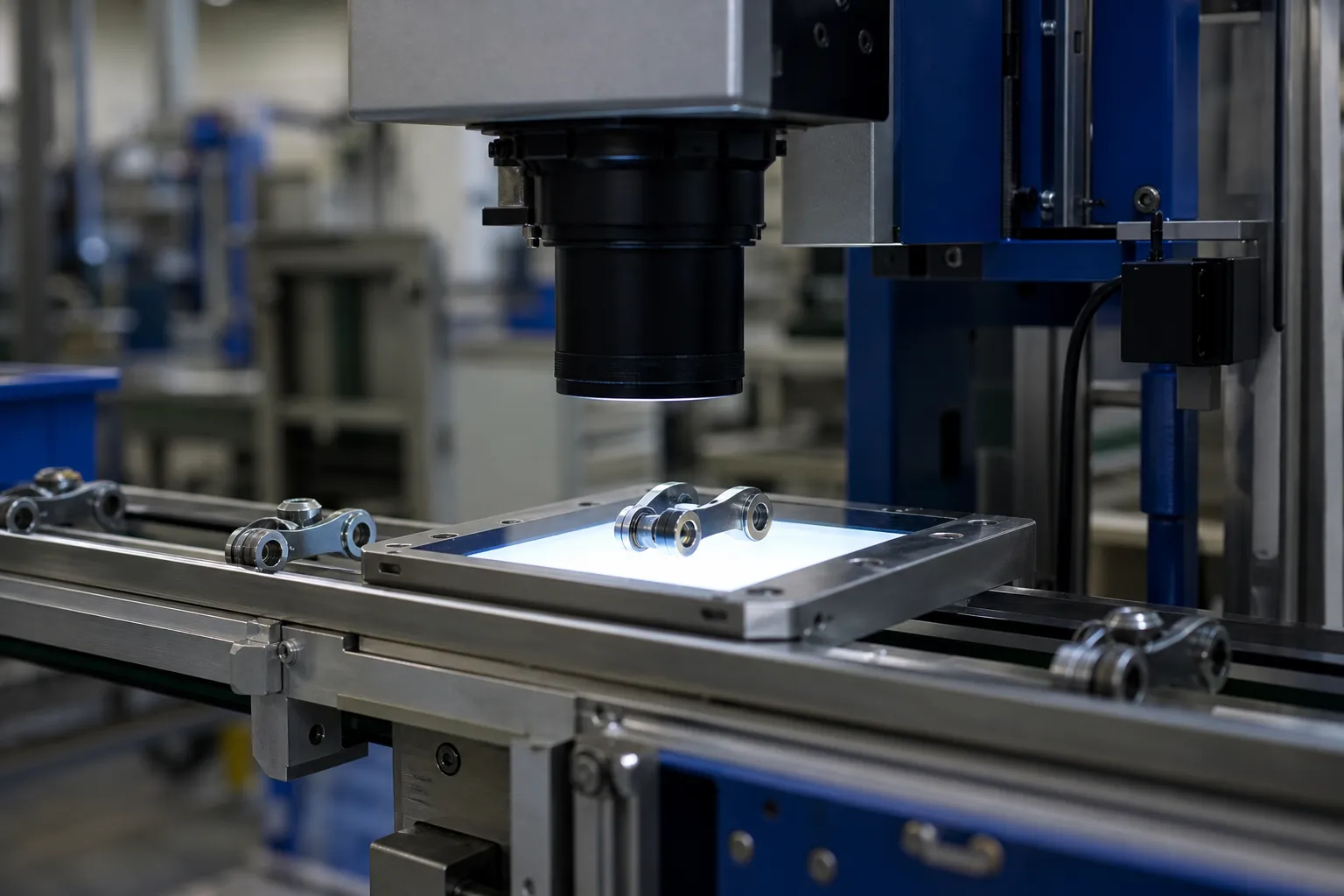
*Engineering concept illustration: rocker arms held in a nest fixture with a probe on the beam during a correction study. Not a customer-site photograph. Support points, force limits and acceptance values must be validated against the drawing and sample parts.*
A Genuine Content Gap on This Topic
It is worth stating plainly what the public search results contain — and what they do not. For rocker arm straightening, DataForSEO returns almost exclusively forum threads: classic car and Honda twin restorers asking whether arms “not straight” can be saved, diesel and LS owners noticing crooked arms at valve adjustment, GS riders discussing re-profiling and re-hardening. The single non-forum article is a parts catalog guide to rocker arm troubleshooting and replacement, which classifies arms as forged, cast and stamped and prices the replacement job. Nothing in the top results describes an engineering-grade correction process for rocker arm distortion in production.
That gap is understandable — most workshops replace a suspect arm rather than correct it, and for a finished arm from an unknown service history that is the right call. But in component manufacturing the situation is different: distortion is measured at a defined process point, the load history is known, and scrap rates on high-volume valvetrain parts justify a controlled correction station. The rest of this page is written from production engineering principles on that basis, with forum consensus retained where it carries real signal (forum mechanics are correct, for example, that visibly crooked arms at adjustment usually indicate geometry or trunnion wear problems rather than parts that “settled”).
Arm Families Behave Differently
| Rocker Arm Family | Typical Use | Correction Behavior |
|---|---|---|
| Forged steel arm | Diesel, heavy-duty, high-load engines | Most tolerant to controlled cold pressing; generous but not unlimited ductility |
| Cast iron arm | Passenger-car pushrod and SOHC engines | Limited correction window; brittle fracture risk rises with hardness and prior load |
| Stamped steel arm | High-volume small engines and economy engines | Usually corrected by die re-calibration or forming correction, not free point-pressing |
| Roller rocker (needle trunnion, roller tip) | Performance and modern efficient engines | Geometry-critical; correction must also protect trunnion bore and roller axis parallelism |
The family decides the process philosophy before any fixture is drawn. Forged arms earn a press-and-measure station; stamped arms belong in a calibration die that restores the whole stamping geometry at once; cast arms get the narrowest validated window and an honest scrap rate.
Functional Geometry and the Datum Chain
The measurement datum system for a rocker arm follows its function:
- pivot bore (or trunnion bore) on a mandrel — primary axis datum;
- valve-side pad face and pad radius position — controls lift curve and valve tip contact;
- cam-side pad face or roller axis — controls contact geometry and friction;
- beam centerline — the structural link whose deviation couples into both pads;
- adjuster screw bore and thread, where fitted — lash setting integrity;
- overall arm length between pad contact zones — effective rocker ratio.
The two pad geometries and the bore axis are what the valvetrain sees. Everything else matters only as it moves those three. This is the crucial simplification for measurement design: a fixture that masters the bore and probes both pad faces — position and angular attitude — captures the functional deviation of the part in three or four readings per side.

Deformation Modes: Name Them Before Pressing Them
| Mode | Measurement Signature | Consequence If Uncorrected |
|---|---|---|
| In-plane beam bend | Pad-to-pad length and angle error in the valve-motion plane | Changed effective ratio; lash drift; valve tip side loading |
| Out-of-plane bend | Pads displaced laterally relative to bore axis | Edge contact on valve tip and cam; uneven wear bands |
| Twist between bore and pads | Pad attitude error when rolled on the mandrel | Skewed contact; ticking noise; roller misalignment |
| Pivot bore distortion | Bore roundness, size or parallelism error | Trunnion or stud fit problems; belongs to sizing, not bending |
The forum instinct — “the arm looks crooked, bend it back” — collapses four engineering cases into one, and the correction that fixes an in-plane bend is exactly the load path that worsens a twist. The mode must be named from measurements before any load is applied. The same discipline is what separates professional valvetrain-part processes such as engine valve straightening from workshop improvisation; the shaft-family equivalent is documented for camshaft straightening, where intentional eccentric geometry makes mode identification equally critical.
Correction Process on a Micro Press

Rocker arms are small and stiff, which changes the character of the process: forces are low, deflections are fractions of a millimetre, and springback is a large fraction of every stroke. A servo-driven micro press with repeatable stroke resolution, supporting the part on miniature anvils directly adjacent to the loaded point, is the right architecture. The working cycle is:
- Load the arm on the mandrel-based fixture; capture pad position and attitude on both sides.
- Transfer to the correction nest; supports under the bosses, load at the beam location the map identifies for the named mode.
- Apply a small measured stroke, release, and re-measure — never assume the correction held.
- Iterate with adjusted overstroke as springback is learned for that part’s hardness batch.
- Finish with a full both-sides pad map and bore check before release.
Two material rules bound the window. First, correction loads go into the beam, never onto a hardened pad face or radius — pressing on the induction-hardened contact zone risks cracking the very surface the arm exists to provide. Second, arms hardened above the window validated for the material are rerouted or scrapped; hardness per batch is an input to the process parameters, which is why springback learned on one lot is not automatically valid on the next. For parts where heat treatment is the distortion source rather than the correction obstacle, the process rules in straightening after heat treatment apply directly.
Acceptance and Verification
Acceptance for a corrected rocker arm should be stated geometrically, not visually:
- pad face position and angular attitude relative to the bore axis, within drawing limits on both pads;
- pivot bore size, roundness and parallelism re-verified after any pressing;
- no cracks — magnetic particle or equivalent for ferrous arms after correction;
- correction count per part logged and capped; parts needing repeated strokes are scrapped, not nursed;
- periodic audit of released parts on a CMM or vision system against the golden master.
On high-volume stamped arms, optical vision measurement is often the practical verification: pads and bores measured in one image per part, at line rate, with NOK sorting automatic. Repeated-correction caps matter more on rocker arms than on long shafts because the part is cheap — the economics of the station come from catching distortion early and correcting once, not from heroic rework, a boundary condition covered in our discussion of rework limits in a straightening line.
Common Pitfalls
- Pressing the mode you can see. A visually crooked beam may carry a twist; without pad-attitude data the correction addresses the wrong mode.
- Loading on hardened zones. Contact pads and radii are the functional surfaces; correction loads belong on the beam between bosses.
- Ignoring bore distortion. Beam correction can close or bell the pivot bore; a bore that is no longer round makes the pad map meaningless.
- Springback assumed constant. Hardness varies between heats and batches; unverified overstroke produces under-correction or cracked parts.
- Correcting service-worn arms. Wear-damaged pads and stretched arms from unknown service loads are replacement cases; the process window covers manufacturing distortion only.
Where Distortion Is Detected in Production
Knowing the process points at which rocker arm distortion appears determines what the correction station must handle. In practice deviations surface at three stages, each with a different population:
- After forming or forging: beam geometry as-struck or as-forged, with batch-dependent spread; deviations are larger but the material is soft and correction is easy.
- After heat treatment: the dominant source of scrap. Quenching and tempering move beams and boss positions unpredictably between parts in the same basket; hardness is now at its peak and the correction window is at its narrowest.
- After pad grinding or finish machining: small residuals and bore-related distortion; correction is limited and mostly diagnostic — a rising deviation here points back to grinding parameters or stress relaxation rather than to the arms.
The detection method should match the stage. Post-forging arms can be sampled statistically with a hard gauge; post-heat-treatment arms need 100 percent measurement because the distribution is wide and non-Gaussian — a batch average tells you nothing about the tail that will tick in a customer engine. On high-volume lines this is where automated correction economics appear: one hundred percent probe measurement, one-or-two-stroke correction on the salvageable population, automatic NOK sorting of the rest, and a scrap ratio tracked per heat-treatment load as a process signal for the furnace, not just for the arms.
That last point deserves emphasis. A correction station produces a stream of data about upstream processes: if distortion jumps after a particular carburizing load, the straightening statistics say so before the warranty department does. Plants that log correction values per batch treat the station as a process monitor; plants that do not, treat it as a scrap reducer and leave the information on the floor.
What a Serious Inquiry Contains
A rocker arm correction station is quoted from facts, not from arm samples alone: the drawing with pad and bore tolerances; the arm family, material and hardness at the correction point; where in the process distortion is detected and with what measured distribution; sample parts in good, borderline and NOK conditions; required cycle time per part; and the plant’s scrap-versus-rework policy. With those, the fixture, probe plan and micro-press specification follow — and the station pays for itself in reduced scrap on parts where a fraction of a millimetre of geometry is the entire specification. For neighboring valvetrain and drivetrain components, see also our connecting rod straightening solution.