
Small motor worm shafts are used in compact gear motors, smart locks, appliance drives and automotive actuators. Their long, small-diameter body can bend after thread machining, heat treatment, grinding or handling. Even a small deviation may affect bearing assembly, worm-wheel contact, noise and rotational stability.
A suitable straightening solution must do more than press the shaft. It needs to establish a repeatable datum, rotate and measure the workpiece, identify the magnitude and angular position of the bend, apply a controlled correction on a safe shaft section, and remeasure the result. The target runout, measuring points and allowed pressing areas must be confirmed from the drawing and sample test before the machine is configured.
For broader threaded-shaft applications, see our precision screw straightening overview. This worm-shaft page focuses on the extra datum, feature-protection and correction challenges created by a functional worm section and stepped journals.
What Is a Small Motor Worm Shaft and Why Does It Need Straightening?
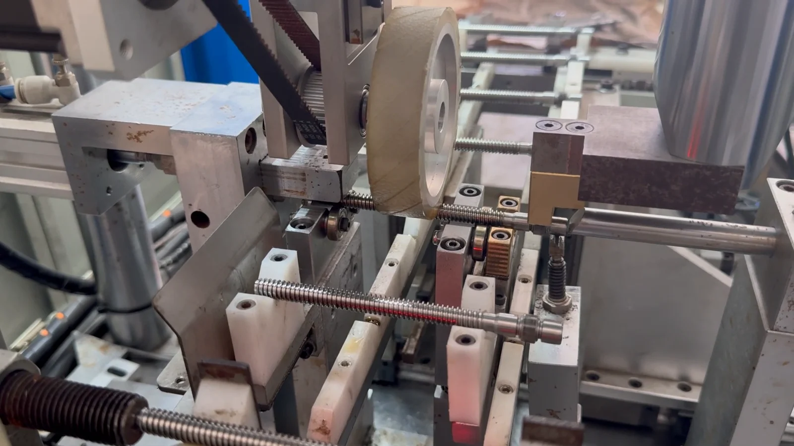
A small motor worm shaft combines a motor shaft with a worm thread that drives a mating worm wheel. Depending on the design, the same part may also include bearing journals, shoulders, grooves, rotor seats and assembly ends. These different diameters and functional features make the shaft more difficult to support and measure than a constant-diameter pin.
The public demonstration used on this page is titled “Precision worm shaft straightening.” Its video description reports an M8 × 180 mm screw/shaft and a requested straightness of 0.1 mm. Those values describe the demonstration input; they are not a universal machine range or independently verified final result. Material, hardness, thread location, datum and heat-treatment condition must still be confirmed for each project because they directly affect stiffness, springback, crack risk and the required correction stroke.
| Item | Project Input |
|---|---|
| Workpiece | Small motor worm shaft |
| Public Demo Input | M8 × 180 mm; video description states 0.1 mm straightness requested |
| Functional Features | Worm thread, slender shaft body, bearing journals, shoulders and assembly ends |
| Material / Hardness | To be confirmed |
| Possible Distortion Sources | Thread machining, heat treatment, grinding, transport or storage |
| Main Quality Characteristic | Radial runout or straightness, as specified on the drawing |
| Measuring Datum | Normally selected bearing journals, centers or designated reference diameters |
| Protected Areas | Worm thread, finished journals, grooves, shoulders and assembly surfaces |
| Production Requirement | Part mix, takt time, annual volume and loading method to be confirmed |
Straightening Target and Acceptance Criteria
Straightness and radial runout are related but not interchangeable. Straightness describes deviation from an ideal straight line. Radial runout is measured while the shaft rotates around defined references and includes the influence of the selected datum. The drawing and the customer's inspection method must therefore be reviewed before a target is entered into the machine recipe.
For a stepped worm shaft, measuring on the thread or across a shoulder can create a misleading signal. Stable cylindrical journals are normally better reference or measuring surfaces, provided that they represent the functional assembly datum. If the production inspection uses centers, bearing journals or another dedicated datum, the machine should reproduce that condition as closely as practical.
| Control Item | Requirement | Verification |
|---|---|---|
| Initial radial runout | Record actual incoming range | Rotate the shaft and measure at defined points |
| Final TIR / straightness | To be confirmed from drawing | Automatic remeasurement using the agreed datum |
| Worm thread protection | No unacceptable press or clamp damage | Visual and functional inspection as required |
| Journal surface protection | No unacceptable support marks | Visual or surface inspection |
| Correction limit | Maximum cycles and stroke set by sample test | Machine recipe and alarm logic |
Why Small Motor Worm Shafts Are Difficult to Straighten
The high length-to-diameter ratio makes the shaft sensitive to both real bending and measurement error. Dirt on the supports, unstable contact, self-weight and an unsuitable measuring point can all change the reading. The machine must distinguish the actual bend from variation caused by steps, grooves or surface features.
The correction window can also be narrow. Too little over-bending leaves residual runout, while too much can reverse the bend or overload a thread root, groove or section transition. For this reason, support spacing, press position, press direction and stroke cannot be copied from another shaft model without validation.
| Challenge | Cause | Control Strategy |
|---|---|---|
| Unstable measurement | Small diameter, surface contamination or poor support | Clean reference areas, precision supports and repeatable rotation |
| Signal variation | Steps, grooves and thread geometry | Measure on approved journals and filter feature-related variation |
| Springback | Material and hardness variation | Closed-loop correction with model-specific limits |
| Overcorrection | High sensitivity of the slender section | Fine displacement control and staged correction |
| Thread damage | Pressing or clamping on the worm profile | Define the worm section as a protected/no-press zone |
| Secondary bend | Incorrect support span or correction sequence | Validate support and press positions through sample testing |
Recommended Straightening Method
For this type of stepped, short and slender shaft, automatic point press-straightening with rotational runout measurement is generally more suitable than a continuous multi-roll process. Point correction allows the system to use designated journals as references, avoid the worm thread and apply a model-specific correction at selected axial and angular positions.
A multi-roll or through-feed process may be suitable for constant-section bars, wire or some uniform shafts, but it should not be assumed suitable for a worm shaft with steps and protected functional features. The final machine concept should be selected only after reviewing the part family, initial runout distribution, tolerance, volume and required changeover time.
Closed-Loop Automatic Straightening Process
The proposed process uses a measure–calculate–press–remeasure loop. The measuring system first creates a runout profile at defined axial positions. The control then identifies the correction point and direction, positions the safe shaft section relative to the press tool, and applies a limited over-bending stroke to compensate for elastic springback.
After each correction, the shaft is measured again using the same datum. The part is accepted only when all required points are within the confirmed tolerance. If the result remains outside tolerance after the permitted number of cycles or reaches a force/stroke limit, the machine should classify the part as NOK instead of continuing uncontrolled correction.
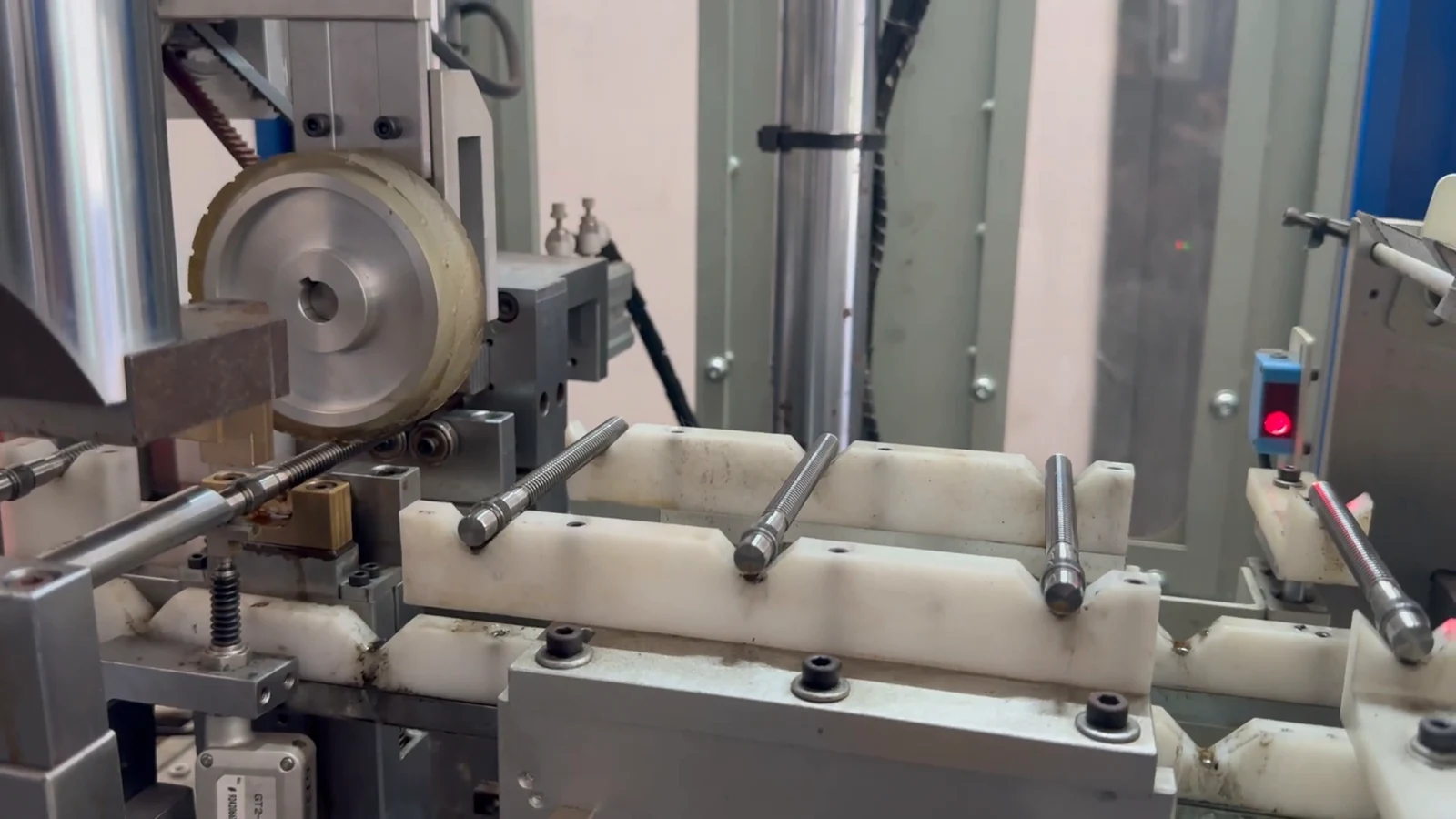
The 48-second video shows threaded worm shafts, the internal support/correction station and parts moving through the machine. It does not show the drawing datum, a readable before/after gauge record, the complete takt calculation or independently prove that every part achieved 0.1 mm. The stated value remains a requested demo input until a documented sample report is available.
| Step | Process | Key Control |
|---|---|---|
| 1 | Identify the shaft model | Load the correct tolerance, measuring points and tooling recipe |
| 2 | Load and position | Support approved reference sections without contacting the worm thread |
| 3 | Rotate and measure | Record runout magnitude and angular position at defined points |
| 4 | Calculate correction | Select the bend peak, safe press point, support span and initial stroke |
| 5 | Index the shaft | Align the bend direction with the press axis |
| 6 | Apply controlled over-bending | Limit displacement and, where configured, monitor force |
| 7 | Remeasure and adapt | Compare the new result with the target and calculate the next action |
| 8 | Accept or reject | Use tolerance, cycle and safety limits to determine OK/NOK |
| 9 | Log and unload | Save available process data and transfer the part |
Initial Measurement
The shaft is placed on miniature supports or between suitable centers, depending on the agreed production datum. The fixture must prevent axial movement while allowing stable rotation. Sensors measure only at approved cylindrical sections; the worm thread is not treated as a normal measuring surface unless a dedicated method has been validated.
Correction Calculation and Press Positioning
The controller uses the measured waveform to determine the angular direction and axial location of the dominant bend. It then selects an allowed press point and support position from the model recipe. Grooves, shoulders, thread roots and abrupt section transitions should be excluded or specially evaluated because they can concentrate stress.
Controlled Over-Bending and Springback
Straightening requires the shaft to be bent beyond its final target so that it settles closer to straight after elastic springback. The required over-bending depends on the material condition and local section stiffness. It should be established from controlled sample trials and refined by the measured response, not by an unsupported universal coefficient.
Remeasurement and Sorting
The same measuring sequence is repeated after correction. A qualified part moves to the OK output. A part that reaches the permitted correction count, force, displacement or measurement-consistency limit is moved to NOK or manual review. This protects the part and prevents a machine from hiding an unstable upstream process through excessive correction cycles.

Engineering Difficulties and Control Strategy
Difficulty 1: Establishing a Functional Datum
The visually straightest surface is not always the correct datum. Bearing journals or centers may determine how the shaft runs in the motor, while other diameters may be non-functional machining surfaces.
The solution is to align machine measurement with the drawing and the customer's final inspection method. Datum selection, support contact and sensor locations should be documented in the recipe and in the acceptance test.
Difficulty 2: Protecting the Worm Thread
The worm thread transmits load and controls meshing with the worm wheel. Direct pressing, hard clamping or incorrect support near the thread can damage the profile or concentrate stress at the root.
The worm area should be defined as a protected zone. Pressing should occur on an approved smooth section, and support materials and contact geometry should be selected to avoid unacceptable marks on finished journals.
Difficulty 3: Controlling a Small Correction Window
On a slender shaft, a small change in stroke may produce a meaningful change in runout. Batch variation in hardness and heat treatment can also change the response.
The control strategy is staged correction with conservative initial limits, followed by remeasurement and adaptation. Recipe limits should include maximum stroke, maximum cycles and plausibility checks for inconsistent sensor data.
Difficulty 4: Managing Several Shaft Models
Different worm shaft models may change in overall length, journal position, thread length and safe pressing zones. A single fixture or program may not cover them reliably.
Changeover should be based on a validated model matrix. Each recipe needs its own datum, measuring points, protected zones, support locations and correction limits. Mechanical poka-yoke, barcode or DMC selection can be added when the production line requires model traceability.
Recommended Cell Configuration
| Module | Proposed Configuration |
|---|---|
| Machine | Precision automatic point straightening machine for small shafts |
| Measuring | Fine-contact displacement probes or another validated runout system |
| Rotation | Controlled shaft rotation on precision supports or centers |
| Press Unit | Fine-displacement servo-electric or precision hydraulic unit, sized by test |
| Tooling | Model-specific miniature supports and protected press contact |
| Controls | HMI recipes, closed-loop correction, cycle/stroke limits and OK/NOK logic |
| Loading | Manual for low volume; feeder, conveyor or robot for validated high-volume parts |
| Data | Before/after readings, correction count and part result where required |
| Safety | Interlocked guarding, overload protection and abnormal-measurement alarms |
For a high-volume family with suitable geometry, the UBJ-L400 automatic feeding screw straightening machine is one equipment concept to evaluate. Its suitability for a particular worm shaft still depends on the drawing, datum, tooling, force/resolution window and sample trial; the product page is not a substitute for feasibility validation.
Proposed Validation Plan
This page describes a proposed solution, not a verified customer case. Before final quotation, representative samples from the expected material and heat-treatment range should be tested. The test should confirm the datum, incoming runout distribution, achievable result, support and press positions, surface condition, correction count and any crack or thread-damage risk.
The acceptance report should clearly separate the customer's target from measured sample results. If mass-production data is later available, the page can be upgraded to a manufacturing case with documented sample size, inspection method, cycle time and customer-approved results.
Information Needed for a Straightening Proposal
Please provide the shaft drawing, material and hardness, heat-treatment and machining stage, overall length and all relevant diameters, worm thread position, bearing-journal locations, initial runout range, final tolerance, inspection datum, allowed pressing areas, protected surfaces, required takt time, annual volume, loading method and representative samples.
These inputs allow the engineering team to select the measurement method, support spacing, press position, force/stroke range, correction logic and automation level. They also prevent a quotation from being based only on the shaft name or an external photograph.
FAQ
What runout can the machine achieve?
The achievable result depends on the shaft geometry, datum, material, hardness, initial bend, surface condition and measuring method. A guaranteed value should be based on the drawing and representative sample tests.
Can the machine protect the worm thread and bearing journals?
Yes, when the drawing provides safe support and pressing sections. The recipe can exclude the worm thread and other functional areas, while contoured supports help distribute contact on approved surfaces.
How is springback compensated?
The machine applies a controlled over-bending stroke, remeasures the result and adjusts the next correction within validated limits. The response should be learned from actual samples rather than assumed from material name alone.
Can one machine straighten several worm shaft models?
Potentially, if their dimensions, required force, datum and tooling needs fall within the validated machine range. Each model still needs a dedicated recipe and may require change parts.
What happens if a shaft cannot be corrected?
The system should stop when the part reaches its allowed correction count, stroke, force or measurement-consistency limit. It then classifies the part as NOK or sends it for manual review.
What is needed before quotation?
The minimum useful package is a drawing, material and hardness, process stage, initial and target runout, inspection datum, protected areas, takt time, annual volume and sample parts.
Conclusion
Small motor worm shafts combine a slender body with a functional thread and precision journals. Their straightening process depends on accurate datum-based measurement, safe support and press positions, controlled springback compensation and repeatable final inspection.
Contact our straightening solution team with your shaft drawing, initial runout range, target tolerance, production volume and sample information for a feasibility review. We can then match the workpiece to an appropriate measuring, straightening and automation concept instead of recommending a machine from dimensions alone.