Concrete Drill Bit Straightening Solution

Concrete and rotary-hammer drill bits combine a long steel body with helical flutes, a carbide cutting structure and a slotted or profiled drive shank. These features make the workpiece very different from a plain round rod. A measurement probe can follow the flute instead of the true body axis, while an incorrectly placed support or press can damage the carbide joint, cutting head, flute edge or SDS connection.

A concrete drill bit straightening solution must therefore be designed around the exact bit family and manufacturing stage. It should measure a drawing-defined characteristic, correct only approved steel zones and verify both geometry and condition after correction.

Concrete Drill Bits Are Not One Uniform Workpiece

Official product ranges demonstrate substantial construction differences. Bosch lists two-cutter tungsten-carbide plates, four-cutter full-carbide heads, two- and four-flute bodies, special welded tip connections and SDS Plus shanks. Hilti lists solid-carbide multi-cutter heads and quadruple helices. DEWALT lists carbide tips, open-head designs and elongated four-flute bodies.

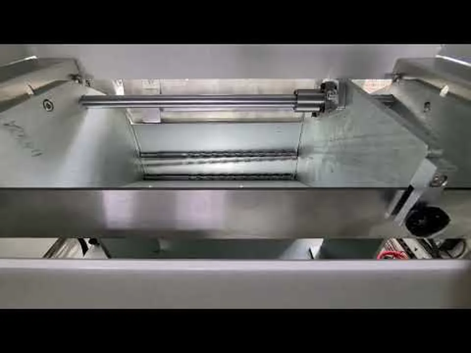
Concrete drill bit held at an automatic measurement and correction station

The image is a real thumbnail frame from the project’s electrical-hammer drill-bit video. It confirms a fluted drill bit, holding station and correction mechanism. It does not establish bit material, dimensions, accuracy or cycle time.

Workpiece featureStraightening consequence
Brazed/welded carbide plateJoint and carbide must normally remain outside the press/support zone
Full-carbide multi-cutter headHigher-value brittle head requires controlled handling and impact protection
Two- or four-flute helixContact measurement changes with axial and angular position
Reduced core or varying flute depthBending stiffness changes along the working length
SDS Plus/Max or other drive shankSlots and drive features are not a plain cylindrical datum
Round, flat or proprietary chuck endRequires variant-specific locator and runout definition
Hardened or surface-treated steel bodyChanges springback, marking and crack risk

Identify the Manufacturing Stage

StagePotential purposeMain restriction
Steel blank before flutingEstablish a straight reference before machining/formingFinal flute/head relationship is not yet present
After flute formingCorrect body distortion before attaching the carbideMeasure through a periodic helical profile
熱處理後Correct thermal distortionHardness, springback and crack limits require validation
After carbide attachmentCorrect assembly or joining distortionProtect carbide and brazed/welded connection
After grinding/coatingMeet final geometryVery strict surface and cutting-edge protection

The safest and most capable stage is not automatically the last one. If a process repeatedly bends bits after an earlier correction, the project should address that upstream cause or move the straightening operation to the appropriate later stage.

Required Project Inputs

輸入Required detail
DrawingRevision, controlled feature, datums and tolerances
Bit family直徑, overall/working length, flute count and core profile
Cutting headCarbide plate/full head, cutter count, joint type and prohibited zones
ShankSDS Plus/Max, 圓形的, hex or proprietary connection geometry
Material routeSteel grade, hardening, carbide attachment and coating sequence
Incoming bendMagnitude, plane and axial distribution from representative batches
Final inspectionStraightness/runout/profile method, gauge, orientation and resolution
Production scopeVariants, output target, loading, changeover and traceability

The previous pages contained no verified size, hardness, accuracy or cycle data. None should be inferred from the video.

直率, Runout and Tip Alignment Are Different

CharacteristicWhat it evaluatesDefinition needed
Body straightnessForm of a selected surface element or derived body axisControlled length and flute-aware evaluation method
徑向跳動Surface variation while rotating about a datumDatum features, probe/optical position and angular sampling
Tip-to-shank alignmentRelationship between cutting head and drive-shank axisHead feature, shank datum and acceptance zone
Flute profile/leadHelical feature geometryAxial range, angular reference and profile method
Functional rotationBehaviour in an approved chuck or test spindleChuck, insertion depth, speed and measured location

ISO 1101 defines the language for geometric specification, but the customer drawing must identify the actual toleranced feature. A machine cannot “ensure straightness or runout” until that choice and datum are explicit.

Flute-Aware Measurement Is Essential

A contact probe touching a rotating helix rises and falls with the flute. That periodic signal can be much larger than the centreline bend being evaluated. SDS slots and flats create the same problem at the drive end.

The measurement concept should use one or more of the following:

  • a defined smooth cylindrical land when the drawing provides one;
  • controlled angular indexing to measure the same flute/land relationship;
  • multiple optical silhouettes and a calibrated centreline/profile model;
  • a non-contact sensor at approved axial positions;
  • a master chuck or centres representing the functional datum;
  • filtering that has been validated against known reference parts, not selected only to make the graph look smooth.

Probe force, support position and clamping force must also be low enough that the slender drill body is not bent by the measurement itself.

Recommended Closed-Loop Straightening Process

1. Identify the bit family

The operator or automation verifies the bit diameter, 長度, flute/head design and shank type. The recipe selects the locator, supports, approved measurement positions, correction limits and prohibited zones.

2. Load without contacting the cutting edges

Tray, magazine or feeder tooling presents one bit without striking carbide against carbide. The head and flute edges remain clear of hard stops. Automatic feeding must be trialled with real length, surface, oil and entanglement conditions.

Magazine and feeding area for concrete drill bits

This frame comes from the correct public concrete-bit machine video and shows the feed area. It does not prove unattended feeding performance, capacity or changeover time.

3. Establish the datum

The bit is held by an approved smooth shank zone, centres or a functional interface. SDS slots are indexed when they influence the locator. The fixture must not clamp the bit into an artificially straight condition.

4. Measure the incoming geometry

Contact or non-contact sensors collect data only at validated positions and orientations. The controller separates the repeatable flute/profile signature from the bend characteristic and stores the incoming result.

5. Select supports and correction point

Supports and the press act on approved steel body zones. The cutting head, carbide joint, flute edge, reduced core, heat-treatment transition and SDS features are excluded unless the drawing and sample test explicitly approve contact.

6. Apply limited point correction

The press applies a controlled displacement or force. Hardened, slender and fluted bits require staged correction with maximum force/stroke and iteration limits. One heavy correction is not a generic strategy.

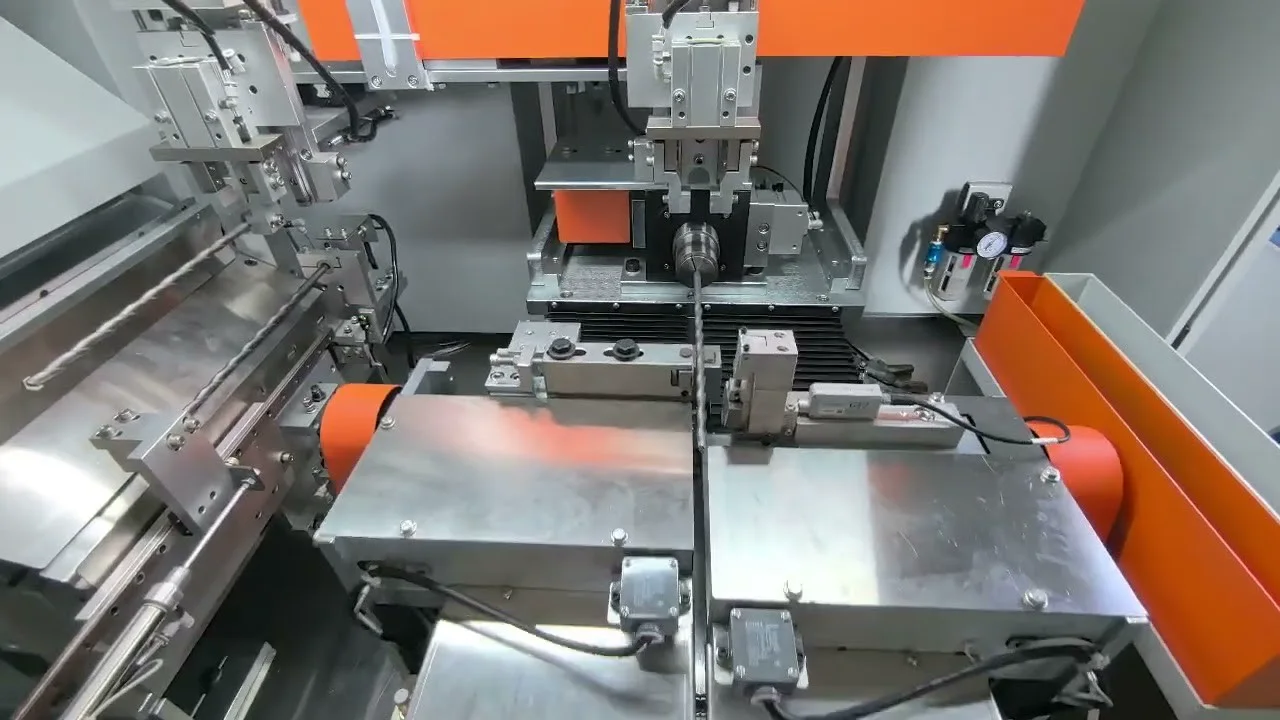
Automatic concrete drill bit measurement and point-correction cell

7. Remeasure using the same datum

The part is remeasured without changing the datum logic. A further correction is allowed only within the validated window. Parts with excessive incoming bend, unstable readings or unexpected springback are separated for review.

8. Verify condition and function

Final checks can include geometry, carbide/joint inspection, flute and coating condition, crack inspection and functional chuck rotation. The required set follows the manufacturing stage and quality plan.

Real Concrete Drill Bit Straightening Video

The following video is titled Automatic Straightening Machine for concrete bit on the Straightening Machine channel. It shows a concrete/rotary-hammer drill bit cell with feeding, holding and correction equipment. It does not prove any particular accuracy, output, yield or customer result.

Surface, Carbide and Joint Protection

風險Control
Carbide tip chipped by handlingSeparate parts and use head-clearance tooling
Brazed/welded joint overloadedDefine an exclusion distance and maximum correction moment
Flute edge dentedUse profile-compatible supports and approved contact zones
Hardened body cracksLimit incoming bend and correction; add required crack inspection
SDS slot used as false datumLocate on drawing-approved surfaces or functional chuck interface
Probe follows helixUse indexed/profile-aware or non-contact measurement
Coating or finish markedValidate contact material, pressure and inspection standard
Bit springs out of fixtureControl clamping and guard the correction area

Point Correction or Roller Straightening?

Decision factorPoint correction may be preferred whenRoller straightening may be evaluated when
Bend distributionHigh points can be measured individuallyCurvature is distributed along a sufficiently uniform body
GeometryHead, flutes and shank require selective contactA continuous roller-contact path is available
測量Closed-loop remeasurement is neededBefore/after in-line measurement can verify the result
SurfaceLocal protected contact is acceptableContinuous roller contact is permitted
Product mixMultiple variants need dedicated recipes/toolingStable higher-volume families share a validated roll setup

The carbide head does not automatically prohibit all straightening, but it narrows the safe contact and correction window. The process is selected from samples and the drawing, not from a universal slogan.

Sample Test and Acceptance Plan

Representative samples

  • smallest body/core and longest flexible variant;
  • each flute count, carbide-head design and shank family;
  • each heat-treatment and coating condition;
  • samples across the real incoming-bend distribution;
  • multiple production batches where joining distortion or springback can vary;
  • boundary parts near the intended correction limit.

Required evidence

RecordAcceptance evidence
Part identityDrawing revision, variant, material route and batch
Incoming geometryDatum, orientation, positions and measured values
ToolingLocator, supports, press and prohibited contact zones
Correction historyLocation, force/displacement and iteration count
Final geometrySame machine setup plus customer-gauge correlation
Head/joint/flute conditionAgreed visual, magnified or NDT result
Functional resultChuck rotation or downstream test when required
Production trialMeasured cycle, feeding stability, changeover and availability

Automation and Changeover

LevelTypical scope
Manual loadingOperator loads; machine measures, corrects and verifies
Magazine/trayControlled presentation for a stable bit family
Automatic cell進食, identification, 測量, correction and sorting
Traceable cellPart/lot, recipe, measurement and correction records

Changing diameter or length may require supports, chuck, sensor position and press-tool changes. Changing from a two-cutter SDS Plus bit to a full-carbide four-cutter or another shank family is not only a PLC recipe change.

What Is Not a Universal Promise

Before drawing review and sample validation, this solution does not promise:

  • one tolerance, cycle time or yield for every concrete drill bit;
  • that straightness and runout are interchangeable;
  • correction of every incoming bend magnitude;
  • zero damage to carbide, joint, flute, coating or shank;
  • automatic feeding for every length and head style;
  • that PLC control eliminates software, tooling or changeover work;
  • a fixed labour saving or production improvement;
  • safe repair of used, impact-damaged or cracked drill bits.

Related Applications

審查 Fastener and Tool Straightening Solutions and the Ball Stud Straightening Machine for adjacent tooling and controlled-correction concepts. Medical and surgical drills remain a separate content family because their workpiece, surface, regulatory and measurement requirements differ.

Information to Send for a Proposal

Send the drawing and revision, representative samples, diameter/length/flute/head/shank range, material and hardening route, carbide attachment method, manufacturing stage, incoming-bend distribution, final characteristic and datum, customer inspection setup, prohibited contact zones, head/joint/flute inspection rules, output target and loading preference.

Contact StraighteningTech for a sample-based concrete drill bit straightening study. We will define the measurement model, protected tooling, correction limits, automation scope and acceptance evidence for the actual bit family.

Frequently Asked Questions

Can the probe measure directly on a helical flute?

Only with a method designed for that profile. A rotating contact probe will otherwise follow the helix and can mistake periodic profile change for centreline bend. Use controlled indexing, a validated profile model, a smooth land or suitable non-contact measurement.

Can the carbide head be used as a support or press point?

Not by default. Carbide and its brazed/welded connection are sensitive functional zones. The tooling normally acts on approved steel body areas with an exclusion distance from the head and joint.

Is an SDS shank a reliable rotation datum?

Only if the drawing or functional test defines it that way and the locator reproduces the approved chuck interface. Its slots and drive features are not equivalent to a complete cylindrical surface.

Should the bit be straightened before or after carbide attachment?

That depends on where distortion is introduced and what final relationship is controlled. Earlier straightening offers safer contact; later straightening can correct joining or heat-treatment distortion but requires tighter protection and correction limits.

Can one recipe cover two- and four-cutter bits?

Not automatically. Head clearance, flute signature, stiffness, datum, support and sensor positions can differ. Each validated family needs the correct tooling and recipe combination.

Technical Reference Boundary

  • Bosch SDS plus-1: https://www.bosch-professional.com/mz/en/sds-plus-1-hammer-drill-bits-2868938-ocs-ac/
  • Bosch EXPERT SDS plus-7X: https://www.bosch-professional.com/gb/en/expert-sds-plus-7x-hammer-drill-bit-2867204-ocs-ac/
  • Bosch SDS plus-3: https://www.bosch-professional.com/in/en/sds-plus-3-hammer-drill-bits-2867846-ocs-ac/
  • Hilti TE-CX: https://www.hilti.com/c/CLS_POWER_TOOL_INSERT_7126/CLS_CONCRETE_MASONRY_DRILL_BITS_7126/r4429
  • DEWALT SDS Plus Masonry Drill Bit: https://www.dewalt.com/en-us/product/dw5443/916-x-10-x-12-rock-carbide-sds-plus-drill-bit
  • MAE Workpieces and Applications: https://mae-group.com/en/workpieces-applications/
  • ISO 1101:2017: https://www.iso.org/standard/66777.html

These references support drill-bit construction diversity and general geometric/straightening principles. They do not prove that another supplier’s performance applies to a StraighteningTech configuration.

目錄
捲動到頂部