
ریلوے ریل ایک عام آئی بیم نہیں ہے۔, لکیری گائیڈ یا ایکسل. اس کا سر, ویب اور پاؤں ایک غیر متناسب فنکشنل پروفائل بناتے ہیں۔, اور عمودی کیمبر, پس منظر جھاڑو, موڑ, اختتامی جیومیٹری اور بقایا تناؤ کے کنٹرول کے لیے مختلف پیمائش اور اصلاح کے راستوں کی ضرورت پڑ سکتی ہے۔.
ایک قابل اعتماد ریلوے ریل سیدھا کرنے کے حل کو مشین کے انتخاب سے پہلے پانچ سوالات کے جوابات دینے چاہئیں:
- جس Vignoles, نالی ہوئی, کرین, زبان, مکمل ویب یا خصوصی ریل فیملی دائرہ کار میں ہے۔?
- ٹاسک مل کی پیداوار ہے, ٹرن آؤٹ کی تیاری, ورکشاپ کا دوبارہ دعوی کرنا, ویلڈ زون کی اصلاح یا ٹریک کی بحالی?
- عمودی اور پس منظر جیومیٹری کو مطلوبہ گھماؤ کو الجھائے بغیر کیسے ماپا جائے گا۔, پروفائل کی تبدیلی, سپورٹ کی غلطی یا موڑ?
- کون سا سر, ویب یا فٹ زمینیں سپورٹ اور ٹولنگ سے رابطہ کر سکتی ہیں۔, اور کون سا چل رہا ہے, گیج, ویلڈ, سوراخ یا مشینی زون محفوظ ہیں۔?
- مکمل طور پر ریلیز ہونے والی ریل کی دوبارہ پیمائش کیسے کی جائے گی۔, تصحیح کے بعد معائنہ اور سراغ لگایا?

*اسٹیشنری سیدھی اور پیمائش کی لائن میں وگنولس ریل کی انجینئرنگ تصور کی مثال. یہ گاہک کی سائٹ کی تصویر یا کارکردگی کا دعویٰ نہیں ہے۔. اصل مشینی قوت, سپورٹ اسپین, ٹولنگ اور قبولیت کی حدود کے لیے کنٹرول شدہ ریل تفصیلات اور نمائندہ نمونے کے ٹیسٹ کی ضرورت ہوتی ہے۔*
ریل فیملی اور پروسیس روٹ کی وضاحت کریں۔
| ریل یا پروسیس فیملی | بنیادی فرق | اس صفحہ پر روٹ |
|---|---|---|
| وگنولس فلیٹ نیچے ریل | گول سر, تنگ ویب اور چوڑا پاؤں | بنیادی اسٹیشنری سیدھا کرنے کا دائرہ |
| نالی ہوئی ریل | نالی اور غیر متناسب سر کو وقف شدہ ڈیٹم اور ٹولنگ کی ضرورت ہوتی ہے۔ | علیحدہ خاندان اور محفوظ رابطے کا نقشہ |
| زبان یا سوئچ ریل | مشینی یا ٹیپرڈ فنکشنل جیومیٹری | خصوصیت سے متعلق پیمائش اور اصلاح کا منصوبہ |
| مینڈک یا پار کرنے والا جزو | پیچیدہ مقامی جیومیٹری اور بوجھ کے راستے | کسٹم فکسچر اور معائنہ کا راستہ |
| Crane or industrial rail | Profile and duty differ from railway running rail | Separate recipe and acceptance inputs |
| New mill rail | Production flow and residual-stress control | Roller or press line selected from profile and process stage |
| Reclaimed rail | پہننا, damage, weld and service history | Inspection-first workshop route |
| In-track rail correction | Portable access, track restraint and operational safety | Outside this stationary factory-cell page |
| Railway axle | Rotating forged shaft with journal datums | Use the railway-axle solution |
| I/H beam | Structural profile with flange/web fabrication errors | Use the beam solution, not the rail recipe |
Stierli-Bieger publicly lists Vignoles, نالی ہوئی, زبان, full-web and special rails, including straightening and torsion correction. Geismar describes a dedicated continuous horizontal rail-straightening machine with an optional route for the other plane. وہ ذرائع ایک خصوصی آلات کی مارکیٹ کی تصدیق کرتے ہیں۔; وہ ہر ریل پروفائل کے لیے ایک ٹولنگ سیٹ کو درست نہیں بناتے ہیں۔.
عمل کے مرحلے کو منجمد کریں۔
مل کی پیداوار
ریل رولنگ کے بعد سیدھا داخل ہو سکتی ہے۔, ٹھنڈک یا گرمی کا علاج. درجہ حرارت کی تاریخ, مواد کا درجہ, پروفائل اور اپ اسٹریم بقایا تناؤ اسپرنگ بیک اور جاری کردہ نتیجہ کو متاثر کرتا ہے۔. تجویز میں یہ بتانا ضروری ہے کہ آیا سٹریٹنر ایک ان لائن پروڈکشن مشین ہے یا ایک علیحدہ فنشنگ اسٹیشن.
ٹرن آؤٹ اور کراسنگ کی تیاری
زبان کی پٹری, مینڈک اور خصوصی پروفائلز میں مشینی شامل ہوسکتی ہے۔, سوراخ, ویلڈز یا مطلوبہ گھماؤ. منظور شدہ جیومیٹری کا اندازہ صرف سیدھی حوالہ لائن سے نہیں لگایا جا سکتا.
ریل کی بحالی
استعمال شدہ ریل سر کے لباس پر مشتمل ہوسکتی ہے۔, نالی, مقامی اخترتی, ویلڈ زونز, سنکنرن, بولٹ سوراخ یا نقصان. تصحیح سے پہلے معائنہ کا طریقہ آتا ہے۔. Geismar دوبارہ دعوی کرنے والی لائن میں انضمام کے لئے ایک وقف شدہ ریل اسٹریٹینر رکھتا ہے۔, نئی مل کی پیداوار سے الگ ورکشاپ کے راستے کی حمایت کرنا.
ویلڈ زون کی اصلاح
مقامی ویلڈ زون جیومیٹری کی خرابی کے لیے ویلڈ کی شناخت کی ضرورت ہوتی ہے۔, گرمی سے متاثرہ زون کا جائزہ, پروفائل کی پیمائش اور قابل اطلاق معائنہ کا راستہ. سیدھا کرنا ویلڈ کے معائنے کی جگہ نہیں لے سکتا اور نہ ہی ناقابل قبول ویلڈ کی مرمت کر سکتا ہے۔.
غلطی کی پیمائش کرنے سے پہلے ریل ڈیٹم کی وضاحت کریں۔
ریل کا حوالہ ڈرائنگ سے طے شدہ فنکشنل جیومیٹری سے لیا جانا چاہئے۔, کسی بھی چہرے کو چھونا آسان نہیں ہے۔. پیمائش کی منصوبہ بندی کی وضاحت کرنی چاہئے:
- ریل خاندان, سیکشن اور واقفیت;
- محوری اصل, اختتامی حالت اور مطلوبہ گھماؤ;
- حمایت کی تعداد, وقفہ کاری, اونچائی اور رابطہ زمین;
- چلنے کی سمت کے ساتھ عمودی پروفائل;
- پس منظر کی جھاڑو مطلوبہ سر کا حوالہ دیا, ویب یا پاؤں کی خصوصیت;
- لمبائی کے ساتھ ہیڈ رول یا سیکشن کی گردش;
- مقامی سربراہ, web and foot profile checks where required;
- end straightness and any excluded end length;
- ویلڈ, سوراخ, machined and transition zones;
- صفائی, پیمانہ, درجہ حرارت اور استحکام کی حالت;
- رہائی کے بعد تکرار کی صلاحیت, repositioning and plane change;
- correlation with the customer's rail gauge and final inspection system.
پڑھیں شافٹ سیدھا پن بمقابلہ رن آؤٹ بمقابلہ TIR for the general distinction between a stationary geometry profile and a rotating indication. A railway rail is normally evaluated as a supported profile; applying shaft runout terminology to it creates the wrong datum model.
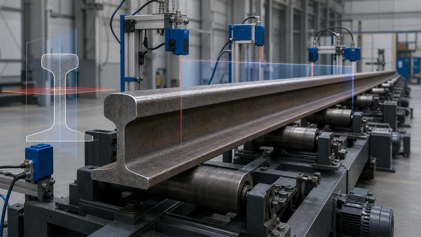
*Engineering concept illustration of vertical and lateral measurement on a head-web-foot rail profile. یہ ایک مقررہ گیج لے آؤٹ نہیں ہے۔. اصل سینسر ٹریکس, سپورٹ وقفہ کاری, intended curvature and acceptance bands require the controlled rail drawing and customer gauge correlation.*
Separate Error Modes Before Applying Force
| مشاہدہ شدہ سگنل | ممکنہ وجہ | مطلوبہ راستہ |
|---|---|---|
| Smooth vertical curvature repeated after support reset | Vertical camber or bow | توثیق شدہ عمودی ہوائی جہاز کی اصلاح کے لیے امیدوار |
| ہموار پس منظر انحراف کو دوبارہ جگہ دینے کے بعد دہرایا گیا۔ | لیٹرل جھاڑو | ضمنی اداکاری کی اصلاح کے لیے امیدوار |
| سر اور پاؤں لمبائی کے ساتھ مخالف سمتوں میں شفٹ ہوتے ہیں۔ | سیکشن کی گردش یا موڑ | ٹورسن مخصوص پیمائش اور ٹولنگ |
| مقامی سمت میں تیز تبدیلی | کنک, اثر یا مقامی اوورلوڈ | اصلاح سے پہلے معائنہ اور انجینئرنگ کا جائزہ |
| سپورٹ سپیسنگ کے ساتھ سگنل کی تبدیلیاں | سپورٹ انحراف, سست یا غیر مستحکم ہینڈلنگ | سپورٹ کی حالت کو منجمد کریں اور پیمائش کو دہرائیں۔ |
| صرف ایک ویلڈ کے قریب ہائی خرابی | ویلڈ زون جیومیٹری یا گرمی سے متاثرہ مسخ | ویلڈ مخصوص معائنہ اور اصلاح کا راستہ |
| رننگ سطح پہنی جاتی ہے جبکہ سنٹر لائن قابل قبول ہوتی ہے۔ | سر پہننا یا پروفائل کا نقصان | ری پروفائلنگ یا مسترد روٹ; سیدھا مواد کو بحال نہیں کرتا ہے۔ |
| جیومیٹری مطلوبہ وکر سے میل کھاتی ہے لیکن سیدھی لائن کی جانچ میں ناکام ہوجاتی ہے۔ | غلط برائے نام حوالہ | درجہ بندی سے پہلے کنٹرول شدہ ڈیزائن جیومیٹری کو لوڈ کریں۔ |
| جسم قابل قبول ہے لیکن اختتامی زون باہر ہے۔ | کولنگ ختم کریں۔, کاٹنے, ہینڈلنگ یا مقامی عمل کی خرابی۔ | اختتامی مخصوص اصلاح یا مشینی جائزہ |
سر کی حفاظت کرو, ویب اور فٹ
ڈیفالٹ پروٹیکٹڈ یا ریویو زونز
- کسی منظور شدہ رابطہ ٹرائل کے بغیر دوڑنے اور سطحوں کو گیج کرنا ختم;
- پتلے ویب کنارے یا غیر تعاون یافتہ ویب علاقے;
- پاؤں کے کنارے جہاں توجہ مرکوز لوڈنگ مقامی نقصان کا سبب بن سکتی ہے۔;
- ویلڈ اور گرمی سے متاثرہ زون جب تک کہ معائنہ درست کرنے کی اجازت نہیں دیتا;
- بولٹ سوراخ, مشینی سوئچ کی خصوصیات اور منسلک زون;
- شناخت اور سراغ لگانے کے نشانات;
- پہنا ہوا, پھٹے, spalled, corroded یا اثر سے تباہ شدہ علاقے;
- جان بوجھ کر مڑے ہوئے یا ٹیپرڈ فنکشنل ریجنز.
ممکنہ طور پر منظور شدہ رابطہ زون
- چوڑا سر, ساختی تجزیہ اور نمونے کی آزمائشوں کے ذریعے منتخب کردہ ویب یا فٹ زمین;
- ریل پروفائل سے مماثل بدلی جا سکتی سیڈلز یا ڈریسنگ بار;
- کنٹرول شدہ رولر رابطے سطح کے دباؤ اور مارکنگ کے لیے اہل ہیں۔;
- نامکمل یا بعد میں مشینی زونز جب پروسیس پلان واضح طور پر رابطے کی اجازت دیتا ہے۔.
ہر پریس فورس کو مکمل سپورٹ/ری ایکشن/لوڈ پاتھ کی ضرورت ہوتی ہے۔. ٹولنگ کا انتظام جو ہموار بیم کے لیے کام کرتا ہے ریل کے سر کو اوورلوڈ کر سکتا ہے۔, ویب یا پاؤں کیونکہ ریل سیکشن غیر متناسب ہے۔.
دو طیاروں کی اصلاحی فن تعمیر کا انتخاب کریں۔
افقی یا سائیڈ ایکٹنگ پریس
ایک افقی ہائیڈرولک پریس ایڈجسٹ ایبل ابٹمنٹس کے ساتھ لیٹرل سویپ کو ایڈریس کر سکتا ہے۔, مقامی افقی موڑ اور کنٹرول ریل موڑنے. Stierli-Bieger عوامی طور پر حرکت پذیری کی وضاحت کرتا ہے۔, لیزر سے تعاون یافتہ کنٹرول اور کچھ کنفیگریشنز میں ریل کو موڑے بغیر موڑنے کی سمت تبدیل کرنے کی صلاحیت.
تجویز کی وضاحت کرنی چاہئے۔:
- منظور شدہ ردعمل زمین اور پریس پوائنٹ;
- abutment وقفہ کاری اور ایڈجسٹمنٹ کا طریقہ;
- طاقت, نقل مکانی اور حد سے زیادہ موڑنا;
- اسپرنگ بیک منطق از ریل فیملی اور عمل ریاست;
- طویل پروڈکٹ کنویرز اور کرین تک رسائی;
- ہر پابند اصلاح کے بعد پس منظر کی پیمائش جاری کی۔.
عمودی تصحیح
عمودی کیمبر کے لیے عمودی بوجھ کا راستہ یا ایک توثیق شدہ ریل ٹیلٹنگ اسٹیشن کی ضرورت ہوتی ہے جو ضروری ہوائی جہاز کو پریس میں منتقل کرتا ہے۔. ہینڈلنگ سسٹم کو ریل کو گھمانے یا دوبارہ جگہ دیتے وقت نیا موڑ نہیں لانا چاہیے۔.
رولر سیدھی لائن
ہائی والیوم مل ریل ترتیب وار افقی استعمال کر سکتی ہے۔- اور عمودی محور رول سسٹم. فائیوز عوامی طور پر دونوں افقی استعمال کرتے ہوئے ریل سیدھے کرنے والوں کی وضاحت کرتا ہے۔- اور عمودی محور مشینیں, جبکہ Iconsys کیس اسٹڈی کنٹرولڈ رول پوزیشن کے ساتھ سیریز میں دو مشینوں کی وضاحت کرتی ہے۔, رفتار اور torque. اس فن تعمیر کو پروڈکشن فیملی لفافے اور بقایا تناؤ کی تصدیق کی ضرورت ہے; یہ ورکشاپ پوائنٹ پریس کے ساتھ قابل تبادلہ نہیں ہے۔.
ٹورسن سیدھا کرنا
ریل کو ایک سادہ عمودی کمان کی طرح سمجھ کر موڑ کو قابل اعتماد طریقے سے درست نہیں کیا جا سکتا. اسے سیکشن کے ساتھ کونیی پیمائش کی ضرورت ہے۔, کنٹرول ٹورشن ٹولنگ, پابندی ختم کریں اور دوبارہ پیمائش جاری کریں۔.
پڑھیں پریس سیدھا کرنا بمقابلہ رولر سیدھا کرنا اصلاحی خاندان کا انتخاب کرنے سے پہلے.
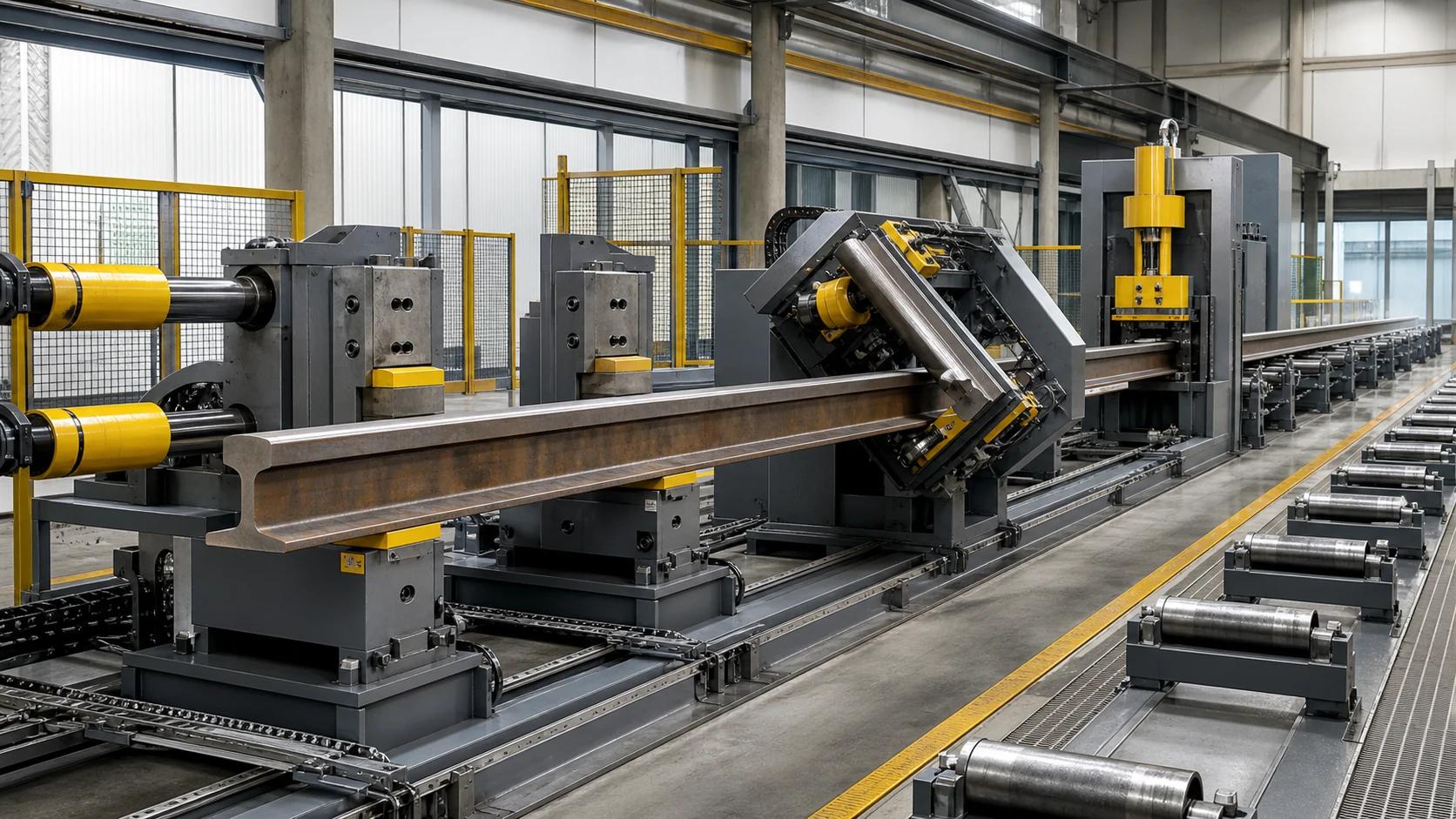
*ضمنی اداکاری کی اصلاح کی انجینئرنگ تصور کی مثال, ہوائی جہاز کی تبدیلی اور بہاو کی تصدیق. یہ ایک عالمگیر مشین لے آؤٹ نہیں ہے۔. اصل ریل ہینڈلنگ, رد عمل جیومیٹری, طاقت, رول پوزیشن اور بقایا تناؤ کی حدود کے لیے پروجیکٹ انجینئرنگ اور نمونے کے ٹرائلز کی ضرورت ہوتی ہے۔*
عمل میں بھاری ہینڈلنگ بنائیں
لمبی ریلوں کو پیمائش اور اصلاح کے ذریعے کنٹرول شدہ حرکت کی ضرورت ہے۔. ہینڈلنگ کے تصور میں شامل ہونا چاہئے۔:
- طاقت سے چلنے والے اندراج اور باہر نکلنے والے رولر کنویرز;
- ریل فیملی گائیڈز جو پروفائل کو الجھا یا نقصان نہیں پہنچاتے;
- مثبت محوری پوزیشننگ اور کنٹرول انڈیکسنگ;
- سیٹ اپ اور بحالی کے لیے محفوظ کرین یا منتقلی تک رسائی;
- اصلاحی طیارہ کو تبدیل کرنے کا ایک متعین طریقہ;
- گائیڈز اور سینسر کے ارد گرد پیمانے اور ملبے کا انتظام;
- حفاظت, انٹرلاک اور محفوظ اخراج زون;
- بجلی کے نقصان یا رکاوٹ شدہ اصلاحی چکر کے لیے بحالی کی منطق.
ہینڈلنگ سسٹم پیمائش کی تکرار کا حصہ ہے۔. کنویئر کی اونچائی یا رول کی حالت میں تبدیلی ظاہری پروفائل کو تبدیل کر سکتی ہے اور ذخیرہ شدہ نسخہ کو باطل کر سکتی ہے.
جاری کردہ ریل کی تصدیق کریں۔, بھری ہوئی شکل نہیں۔
- ریل خاندان کی شناخت کریں۔, ڈرائنگ پر نظرثانی اور عمل کا مرحلہ.
- معائنہ کی حیثیت اور مطلوبہ سیدھی یا مڑے ہوئے جیومیٹری کی تصدیق کریں۔.
- منظور شدہ پیمائش اور رابطہ زون کو صاف کریں۔.
- ریل کو منجمد سپورٹ اور ہینڈلنگ کنفیگریشن پر لوڈ کریں۔.
- عمودی پیمائش کریں۔, لیٹرل اور ٹورسنل سگنل الگ الگ.
- رکوع کی درجہ بندی کریں۔, جھاڑو, موڑ, کنک, ویلڈ زون کی خرابی, پہننے اور ترتیب دینے میں خرابی۔.
- دبائیں کو منتخب کریں۔, رولر, ٹارشن, مسترد یا انجینئرنگ کا جائزہ لینے کا راستہ.
- منظور شدہ جہاز اور زون کو تفویض کردہ صرف باؤنڈڈ تصحیح کا اطلاق کریں۔.
- مکمل طور پر ریلیز اور ریل کو مستحکم کریں۔.
- ایک ہی ڈیٹم اور سپورٹ کی حالت کے تحت دوبارہ پیمائش کریں۔.
- صرف طاقت کے اندر دہرائیں۔, نقل مکانی, overbend, تکرار اور سطح کی حدود.
- مطلوبہ پروفائل مکمل کریں۔, سطح, ویلڈ, بقایا تناؤ یا دیگر معائنہ.
- پروفائل سے پہلے / بعد میں اسٹور کریں۔, ہدایت, کوالٹی ڈسپوزیشن اور ٹریس ایبلٹی ریکارڈ.
ریل فیملی کے ارد گرد سیل کو ترتیب دیں۔
| سیل فنکشن | ریلوے-ریل کی ضرورت |
|---|---|
| شناخت | پروفائل, گریڈ, لمبائی, عمل کے مرحلے, مطلوبہ گھماؤ اور ٹریس ایبلٹی |
| سنبھالنا | لمبے کنویرز, محوری پوزیشننگ, ہوائی جہاز کی تبدیلی اور کرین تک رسائی |
| پیمائش | عمودی پروفائل, پس منظر جھاڑو, سیکشن کی گردش اور مقامی پروفائل چیک |
| درجہ بندی | کیمبر, جھاڑو, موڑ, کنک, ویلڈ زون کی خرابی, پہننے اور ترتیب دینے میں خرابی۔ |
| اصلاح | سائیڈ پریس, عمودی پریس, خاندان کے ذریعہ رول لائن یا ٹورشن ٹولنگ |
| تحفظ | رننگ/گیج سطحیں۔, ویب, پاؤں کے کناروں, ویلڈز, سوراخ اور مشینی زون |
| تصدیق | مکمل طور پر جاری کردہ جیومیٹری کے علاوہ قابل اطلاق سطح, ویلڈ اور بقایا تناؤ کی جانچ |
| ڈیٹا | پروفائلز سے پہلے / بعد میں, سیٹ اپ, زبردستی / نقل مکانی, معائنہ اور حتمی شکل |
پروپوزل ان پٹس جو ہمیں درکار ہیں۔
سامان کے انتخاب سے پہلے درج ذیل بھیجیں۔:
- ریل پروفائل ڈرائنگ اور فیملی لسٹ;
- مواد کا درجہ, گرمی کا علاج اور عمل کا مرحلہ;
- لمبائی کی حد اور سالانہ یا شفٹ پروڈکٹ مکس;
- مطلوبہ سیدھا پن یا ڈیزائن کردہ گھماؤ;
- عمودی, پس منظر, موڑ اور اختتامی زون قبولیت کی تعریفیں۔;
- ویلڈ, سوراخ, مشینی, ٹیپرڈ اور محفوظ سطح کے نقشے۔;
- اجازت شدہ سر, ویب اور پاؤں سے رابطہ کرنے والی زمینیں۔;
- آنے والی خرابی کی تقسیم اور نقصان کے معلوم طریقے;
- ضرورت کے بعد عمل کی سطح, ویلڈ, بقایا تناؤ یا NDT چیک;
- لائن بیٹ, کنویئر کی اونچائی اور دستیاب کرین/ہینڈلنگ انٹرفیس;
- نمائندہ اچھا, معمولی اور مسترد نمونے;
- کسٹمر گیج, رپورٹ فارمیٹ اور ٹریس ایبلٹی انٹرفیس.
پروڈکشن ریلیز سے پہلے نمونہ ٹیسٹ قبولیت
نمونے کی آزمائش میں اصل ریل فیملی لفافے اور دونوں اصلاحی طیاروں کا احاطہ کرنا چاہیے۔. اسے سپورٹ کی تکرار کی تصدیق کرنی چاہیے۔, سینسر کا تعلق, رابطہ مارکنگ, عمودی/پس منظر/ٹارشن کی درجہ بندی, اسپرنگ بیک, ہوائی جہاز کی تبدیلی کی ہینڈلنگ, جاری کردہ جیومیٹری اور مطلوبہ بہاو معائنہ.
استعمال کریں۔ سیدھا نمونہ ٹیسٹ اور قبولیت گائیڈ ٹیسٹ میٹرکس اور ثبوت پیکج کو منجمد کرنے کے لیے.
انجینئرنگ باؤنڈری
سیدھا کرنا مناسب ریل میں منظور شدہ جیومیٹرک غلطی کو درست کر سکتا ہے۔. یہ سر کے پھٹے ہوئے مواد کو بحال نہیں کرتا ہے۔, ایک شگاف کی مرمت, ایک ناقابل قبول ویلڈ کوالیفائی کریں۔, ری پروفائلنگ کو تبدیل کریں۔, یا قابل اطلاق ریلوے اتھارٹی اور معائنہ کے طریقہ کار کے بغیر ٹریک کی فٹنس ثابت کریں۔.
مشینی قوت, رول لے آؤٹ, abutment کی مدت, سپورٹ وقفہ کاری, درستگی, سائیکل کا وقت, اوور بینڈ اور تکرار کی گنتی تجویز کی پیداوار ہیں۔. انہیں کنٹرولڈ ریل فیملی سے آنا چاہیے۔, مادی حالت, ڈرائنگ, نمونے اور کسٹمر گیج—نہ کہ کسی مدمقابل تفصیلات کی میز سے.
ریلوے ریل کو سیدھا کرنے کے جائزے کی درخواست کریں۔
ریل فیملی ٹیبل بھیجیں۔, ڈرائنگ, عمل کے مرحلے, غلطی کے نقشے, معائنہ کا راستہ اور نمائندہ نمونے۔. ہم ایک مجوزہ ڈیٹم اور سپورٹ ماڈل واپس کریں گے۔, محفوظ رابطہ نقشہ, دو ہوائی جہاز کی اصلاح کا تصور, ہینڈلنگ کی منصوبہ بندی, جائزہ کے لیے نمونہ ٹیسٹ میٹرکس اور آلات کی ترتیب.