
An I-beam or H-beam is not a round bar with a larger diameter. Its two flanges and web form an open section whose stiffness changes by direction. הַלחָמָה, גְזִירָה, handling and fabrication can create flange angular distortion, longitudinal camber, טאטוא לרוחב, twist or local web deformation. Each error needs a different datum, load path and correction method.
An effective I beam straightening machine must answer five questions before equipment is selected:
- Is the workpiece a rolled section, a welded built-up beam, a tapered beam, a T-section or a fabricated assembly with attachments?
- Is the controlled error flange angular distortion, קִמוּר, לְטַאטֵא, לְהִתְפַּתֵל, web waviness or a combination?
- Where may rollers, supports and press tooling contact without crushing the web, marking a finished surface or loading a sensitive weld zone?
- Does the required correction belong in a continuous flange straightener, a point-press station, a twist/camber system or an engineering-review route?
- How will the fully released beam be remeasured and accepted under the customer's drawing and applicable fabrication procedure?

*Engineering concept illustration of a welded H-beam in a continuous flange-straightening cell. אין מדובר בתצלום באתר הלקוח או בתביעת ביצועים. Actual rollers, מדריכים, section range, force and acceptance limits require the controlled beam family and representative sample tests.*
Define the Beam Family and Production Stage
| משפחת חלקי עבודה | Main difference | מסלול חובה |
|---|---|---|
| Hot-rolled I- or H-section | Geometry comes from the mill; distortion may arise during handling or later fabrication | Confirm mill condition, section properties and permitted cold correction |
| Welded built-up H-beam | Web and flange plates are joined by longitudinal welds; flange angular distortion is a common post-weld error | Flange-specific measurement and continuous or staged correction |
| T-beam | One flange and one web create an asymmetric load path | Dedicated support and guide layout |
| Tapered or variable-depth beam | Web depth and stiffness change along the length | Recipe and tooling position must follow the section map |
| Asymmetric I/H section | Unequal flanges or offset web change neutral axis and springback | Separate family and sample validation |
| Beam with stiffeners, end plates or brackets | Attachments interrupt contact zones and may lock in distortion | Feature-aware handling and local engineering review |
| Galvanized, painted or finish-coated beam | Contact marks and coating damage become acceptance items | Qualified pads/rollers and post-process surface inspection |
| Installed or service-damaged structural member | Loads, cracks and connection history may be unknown | Structural engineering and inspection route, not a production recipe |
This page focuses on controlled shop-floor straightening of rolled or welded beam components before final release. It does not authorize field correction of an in-service structure.
Separate the Distortion Modes
Flange Angular Distortion
Longitudinal welding can rotate or tilt flange edges relative to the web. A dedicated flange straightener uses a controlled roller load against the flange while guiding the beam through the machine. Stierli-Bieger describes hydraulic roller correction in continuous operation for welded beams; Corimpex describes horizontal systems that correct the flanges of welded H-beams as part of a welding line.
This is not the same as correcting the full beam's longitudinal centerline.
Longitudinal Camber
Camber is curvature in the beam's strong-axis plane. It may be intentional or unintentional. The drawing must distinguish designed camber from distortion before any correction command is issued.
Lateral Sweep
Sweep is curvature in the weak-axis plane. It needs a different support and load direction from camber, and the slender web/flange relationship can make the section sensitive to local instability.
לְהִתְפַּתֵל
Twist is rotation of the section along its length. A flange-only roller pass may leave twist unchanged or redistribute it. Twist needs indexed section measurements and a controlled torsion route.
Web Waviness, Buckling or Local Damage
Local web deformation is not automatically a straightening-machine input. Thin-web buckling, שקעים, סדקים, weld defects and heat-affected damage require inspection and engineering disposition before force is applied.
| Observed result | סיבה אפשרית | מַסלוּל |
|---|---|---|
| Both flange edges show a consistent angular error after welding | Weld shrinkage and flange rotation | Candidate for dedicated flange roller straightening |
| Beam centerline curves vertically but section angle stays stable | Camber or strong-axis bow | Measured press or cambering route |
| Beam curves sideways | Sweep or weak-axis bow | Lateral support and correction route |
| Cross-section angle rotates along the length | לְהִתְפַּתֵל | Torsion measurement and dedicated twist correction |
| Short sharp change near an attachment or weld stop | Local restraint, heat input, damage or fabrication error | Inspect and route to engineering; do not average into global curvature |
| Web shows waves while flanges remain aligned | Local web instability or weld shrinkage | Web-specific engineering route; flange straightener may not solve it |
| Measured shape changes when support positions move | Heavy-beam sag or unstable datum | Freeze the support and measurement condition, then repeat |
Establish a Beam-Specific Datum Chain
A long heavy beam can sag on conveyors and can sit differently on worn or unequal rollers. תוכנית הבדיקה צריכה להגדיר:
- beam orientation and axial origin;
- reference flange, web center plane and end section;
- ספירת תמיכה, מרווחים, roller height and overhang;
- whether the result is free-state, controlled-support or fixture-referenced;
- full-length camber and sweep profiles;
- section rotation or twist at controlled axial stations;
- flange-to-web angle on both sides;
- flange width, עוֹבִי, flatness and edge condition;
- web depth, עוֹבִי, flatness and local waviness;
- weld location, weld toe condition and excluded measurement zones;
- יכולת חזרה לאחר פריקה, reversing or rotating the beam;
- correlation with the customer's fixtures, gauges and drawing definition.

*Engineering concept illustration of separate full-length and cross-section measurements. זה לא פריסת מד שנקבעה. Actual sensor positions, support spacing and acceptance calculations require the drawing and customer gauge correlation.*
Protect the Web, Welds and Finished Surfaces
ברירת מחדל אזורי מוגנים או סקירה
- unsupported thin web areas under a concentrated press load;
- לרתך בהונות, weld starts/stops and uninspected weld indications;
- flange edges that define a finished interface;
- חורי ברגים, חריצים, copes and cutouts;
- stiffeners, סוֹגְרַיִם, end plates and connection details;
- identification marks and traceability tags;
- galvanized, painted or architecturally exposed surfaces without qualified contact pads;
- שקעים, סדקים, למינציות, חרקים, severe corrosion or previous repair zones.
אזורי מגע פוטנציאליים מאושרים
- broad flange lands identified by the controlled section drawing;
- reinforced web/flange load-transfer zones supported against local buckling;
- replaceable roller profiles matched to the flange and web geometry;
- clean uncoated surfaces before final finishing when the process plan permits;
- handling points verified for the beam's mass, center of gravity and attachment layout.
The contact map should be revision-controlled by section family. A roller position that suits a parallel-flange H-beam may interfere with a tapered flange, stiffener or asymmetric section.
Select the Correction Method From the Error Map
Continuous Flange Roller Straightening
This method is appropriate when the controlled problem is repeatable flange angular distortion along a weld-fabricated beam. Stierli-Bieger describes one or more passes with rollers set to the workpiece and required correction. Corimpex describes horizontally fed systems with independently positioned correction groups. A production solution still needs to define:
- supported beam orientation;
- roll profiles and clearances for each flange and web range;
- guide positions and anti-twist control;
- pass sequence and bounded roller setting;
- entry/exit conveyor height and synchronization;
- לְרַתֵך, surface and edge protection;
- released flange-angle and full-beam verification.
Point-Press Correction for Camber or Sweep
A hydraulic press can address a measured global or local centerline error when the supports and press point form a safe load path. It requires broad tooling, beam stability, force/displacement limits, springback control and fully released remeasurement. A concentrated load must not be placed on an unsupported thin web simply because it is geometrically convenient.
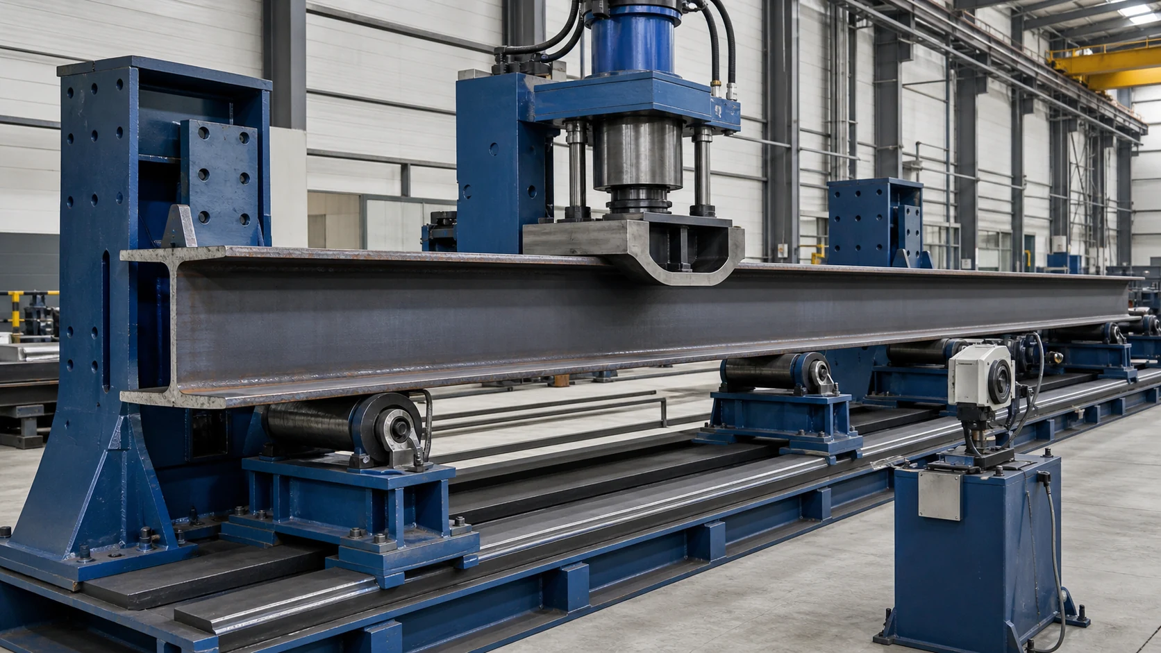
*Engineering concept illustration of a long-beam press station. It is not a universal load case. טווח תמיכה, כלי עבודה, מתח מקומי, buckling resistance, springback and surface condition require sample validation and engineering approval.*
Twist or Multi-Axis Correction
When section rotation varies along the length, the machine needs controlled reaction points and torque application. Flange angle, קִמוּר, sweep and twist must be rechecked after every correction because one operation may move another error component.
יישור חום
Heat straightening is a separate controlled fabrication process. It requires an approved procedure, material and weld review, temperature control and qualified personnel. This page does not treat uncontrolled torch heating as a substitute for a measured mechanical straightening process.
לִקְרוֹא יישור לחץ לעומת יישור רולר להשוואת השיטה הכללית, then apply the beam-specific load-path and instability checks above.
Integrate Measurement, Handling and Safety
Heavy long beams make material handling part of the straightening system rather than an accessory. A production cell may require:
- מסועי גלגלי כניסה ויציאה ממונעים;
- synchronized transport through the correction zone;
- side guides that stabilize without locking in a false datum;
- lifting, turning or 180-degree rotation equipment when both sides require access;
- adjustable roller elevation for section changes;
- end and side presence detection;
- safe zones around moving beam ends and pinch points;
- recipe interlocks for section family and orientation;
- traceability of incoming, intermediate and released measurements.
Bendmak publicly positions H-profile straightening before or after fabrication when flanges or web are warped. Corimpex integrates a horizontal beam straightener with welding, assembly and beam-rotation equipment. These market examples support an integrated-line architecture; they do not establish the capacity or accuracy of a proposed StraighteningTech cell.
Build an Inspection Gate Around Straightening
Before correction, confirm:
- section designation, material certificate and heat or fabrication history;
- drawing revision and intentional camber or taper;
- weld status and required visual or nondestructive inspection disposition;
- attachment, hole and cutout map;
- surface/coating condition and permitted contact zones;
- incoming flange angle, קִמוּר, לְטַאטֵא, twist and local defect map;
- correction eligibility and reject/engineering-review conditions.
לאחר תיקון, repeat the controlled dimensional inspection and any required weld or surface checks. Straightening cannot repair a crack, unacceptable weld, רִבּוּד, חור קרוע, severe local buckle or lost section.
The governing tolerance should come from the customer's drawing and applicable fabrication or product standard. Do not copy a machine supplier's sample range into a project acceptance specification.
External H-Beam Straightening Demonstration
The following external video shows an H-beam flange straightening machine. It is included to illustrate the equipment category, not as a StraighteningTech customer case, machine specification or acceptance proof.
מידע נדרש עבור הצעה טכנית
| קֶלֶט | מינימום פירוט |
|---|---|
| Beam family | Rolled or welded; אני, ח, ט, מתחדדת, asymmetric or fabricated assembly |
| Section range | Overall length, flange width/thickness, web height/thickness and mass |
| Material and stage | צִיוּן, heat condition, weld process, before/after fabrication and coating state |
| Error modes | Flange angle, קִמוּר, לְטַאטֵא, לְהִתְפַּתֵל, web waviness and local-defect map |
| תוצאה נדרשת | סובלנות לציור, נָתוּן, מצב תמיכה, stations and inspection method |
| תכונות מוגנות | Welds, חורים, copes, stiffeners, end plates, coatings and finished interfaces |
| טיפול | שיטת הטעינה, הִתמַצְאוּת, center of gravity, conveyor height and turning requirement |
| צורך בייצור | תמהיל מוצרים, לנצח את המטרה, מעבר, אוטומציה ומעקב |
| Quality plan | Weld/NDT status, surface check, לאמוד מתאם, FAT/SAT ופורמט דוחות |
If the input is incomplete, the first deliverable should be a measurement and sample-test plan rather than an invented force, accuracy or throughput value.
מבדיקה לדוגמה ועד שחרור הפקה
- סקירת ציורים, section families, weld procedures and acceptance documents.
- Separate flange angle, קִמוּר, לְטַאטֵא, twist and local damage.
- Freeze the support, נתון ושיטת מדידה.
- Identify protected and permitted contact zones.
- Measure representative normal and worst-case samples.
- Trial the selected roller, press or multi-axis correction route.
- quantify springback, cross-coupling, surface marking and repeatability.
- Reinspect welds and surfaces according to the quality plan.
- Correlate released results with the customer's gauges.
- הקפאת כלי עבודה, מתכונים, stop limits, handling logic and traceability fields.
- לָרוּץ מבחן וקבלה לדוגמה לפני שחרור המשפחה המאושרת.
For an I-beam and H-beam application like this one, procurement teams usually pair the straightener selection walkthrough with the budget picture for a straightening machine before shortlisting vendors.
Send us your beam drawings, section range, distortion map and acceptance method לקבל קונספט יישור וטיפול. StraighteningTech develops the equipment, כלי עבודה, measurement and verification workflow around the actual beam family rather than applying one generic setting to every profile.