
Iminvarras ei ole lühike üldotstarbeline terasvarras ega õõnes puurtoru. See on pikk, sihvakas, tsükliliselt koormatud komponent varrastõste stringis. Lihtne varda korpus, sepistatud või ärritunud otsad, mutrivõtme omadused, pin õlad, keermed ja pinnad moodustavad ühe kontrollitava tooriku. Materjali klass, kuumtöötlus, katmine, kokkupuude korrosiooniga ja hooldusajalugu võivad muuta ohutut parandusteed.
Usaldusväärne imevarraste sirgendamise lahendus peab enne masina valimist vastama viiele küsimusele:
- Kas toorik on uus terasest imivarras, poni ritv, kasutatud melioratsioonivarras, poleeritud varras, uppumisvarras või komposiitvarras?
- Kuidas eraldatakse täispikkuses kehakõverdus omakaalu langemisest, seadistusviga, lokaalne kulumine ja lõppfunktsiooni nihe?
- Millised tavalised kehapiirkonnad võivad rullide või tugedega kokku puutuda, ja milline tihvt, õlg, niit, nägu või kaetud alad on kaitstud?
- Kas materjali ja ülevaatuse seisukord lubavad korrigeerimist, või tuleks varras enne jõu rakendamist tagasi lükata?
- Kuidas täielikult vabastatud ridva ümber mõõdetakse, kontrollitud, hinnatakse ja jälgitakse pärast parandamist?
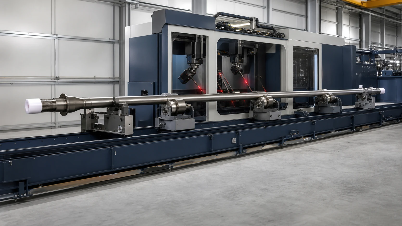
*Tehnilise kontseptsiooni illustratsioon tugevast terasest imivardast pika voodiga mõõtmis- ja sirgenduskambris. See ei ole kliendi saidi foto ega toimivusnõue. Tegelikud toetused, rullid, andurid ja vastuvõtupiirid nõuavad kontrollitud varda spetsifikatsiooni ja representatiivseid näidiskatseid.*
Enne varustuse valimist määrake varraste perekond
SLB eristab avalikult imivardaid, lühemad ponivardad ja mitut tüüpi haakeseadised. API tuvastab, et spetsifikatsioon 11B hõlmab imivardaid ja varrastega seotud tooteid. Neid tooteperekondi ei tohiks käsitleda vahetatavate masinaretseptidena.
| Varraste või komponentide perekond | Peamine erinevus | See leht |
|---|---|---|
| Terasest imemisvarras | Pikk tugev korpus, sepistatud tihvtiotstega | Esmane ulatus |
| Terasest ponivarras | Sarnane otsageomeetria, kuid lühem pikkus | Sama kontseptsioon, eraldi tugi ja retsepti valideerimine |
| Rekultiveerimiseks kasutatud imivarras | Tundmatu teenus, korrosioon, kulumise ja väsimuse ajalugu | Ainult ülevaatus - esimene marsruut |
| Poleeritud varras | Kriitiline tihenduspind ja erinev teenindusasend | Eraldi pinnakaitseprojekt |
| Klaaskiust või komposiitmaterjalist imivarras | Erinev jäikus, rikkerežiim ja ühenduse disain | Väljaspool terasvarda korrigeerimise marsruuti |
| Sinker baar | Raskem sektsioon ja erinev koormuse roll | Eraldi tooriku perekond |
| Sidumine | Sisekeermega pistik, mitte pikk varras | Kontrollige ja käsitsege eraldi |
| Puurtoru, kest või toru | Õõnes torukujuline tööriistade ühenduste või ühendustega | Kasutage naftavälja torukujulist lahendust |
| Pidev varras või spiraalvarras | Erinevad käsitsemis- ja paigaldussüsteemid | Eraldi joone kontseptsioon |
See leht keskendub tugevast terasest imemis- ja ponivarrastele. See ei väida, et torusirgendaja, armatuurmasin või tavaline varda sirgendaja rahuldab automaatselt imivarda kontrollimise ja ühendamise nõuded.
Continuous Rod: A Different Factory, Not a Longer Sucker Rod
Continuous rod — coiled rod, best known by trade names such as COROD — replaces the jointed sucker rod string with a single coiled alloy rod run into and out of the well as a coil. It removes the threaded connections, and with them the dominant fatigue and handling cost of rod lift, at the price of a completely different manufacturing and logistics chain: spool-based transport, injector-head handling, and a rod body that arrives carrying coil curvature memory.
At the manufacturing end, straightening is a continuous-process operation inside the rod mill, not a bench operation. Rod producers describe lines in which the coil passes through straightening, heat treatment and quenching in sequence (reported process descriptions from continuous rod manufacturing), and patent literature describes dedicated multi-roll, two-axis rod straighteners for cold straightening of coiled rod (reported patent documents). This is roller-based, through-feed straightening — a different machine species from the measured single-part correction cells discussed on this page, and the comparison logic in presssirgendamine vs rullsirgendamine explains why the two categories rarely share a supplier.
Where single-part discipline does enter the continuous rod world is localized repair. A continuous rod section can acquire a local bend in transport, spooling or service, and a measured point-press correction of that zone follows the same physics as any rod body correction: map the bend, protect the surface, press in bounded increments, release and remeasure. The project differences are real, aga mähise mälu tähendab, et varras tuleb hoida või toetada selle jääkkõveruse vastu, mitte eeldada, et see peaks olema tasane nagu lõigatud varras, ja käsitsemine on pigem pooli- kui riiulikeskne, mis muudab laadimis- ja tugiriistvara rohkem kui press ise.
Seadmete ostjate praktiline piir: kui nõue on rullitud toote varraste läbilaskevõime õgvendamine, määrake pidev mitme rulliga rida ja hinnake selle kategooria tarnijaid. Kui nõue on eraldiseisvate pideva varraste sektsioonide või kohalike kahjustuste tsoonide uuesti õgvendamine hooldustöökojas, kehtib selle lehe üheosaline parandusloogika, millele eelneb mähise mälu käitumise kinnitusuuring. Kahel projektil on tooriku nimi ja peaaegu mitte midagi muud.
Ponivardad: Lühikesed pikkused muudavad tugimatemaatikat
Pony rods are the length-adjustment members of a rod string: the same forged pin ends as a sucker rod, no coupling in the middle, and much shorter bodies. Supplier catalogs list them in standard increments — reported listings from SLB, ChampionX-Norris and oilfield steel suppliers run from about two feet up to ten feet — and they exist so the string can be spaced to well depth without cutting into a full-length rod.
Shortness changes the straightening problem in three specific ways. Esiteks, the protected fraction grows. Upset ends, wrench squares, pin shoulders and threads occupy roughly the same absolute length as on a full rod, so on the shortest pony rods the approved plain-body zones may amount to a third of the part or less. Support stations and press points must be chosen inside that reduced window — the fixture plan, not operator judgment, has to encode it, and a fixture designed around full-length rods may simply have no legal support positions left when a two-meter pony is on the stands.
Teiseks, the measurement model simplifies — with a caution. A full-length sucker rod deflects under its own weight and demands the frozen support-spacing discipline described later in this article; a short pony rod is stiff enough that self-weight sag between two supports shrinks to a much smaller term. The trap is assuming the simplification carries over automatically: mixed shops still measure ponies on the same controlled supports and record the same stations, because the acceptance question — global bow, end-feature eccentricity, or local damage — does not change with length, and neither does the customer’s grading system.
Kolmandaks, production mixing drives the machine specification. A cell that runs full-length rods and short ponies on the same line needs support stations that reposition across the whole length range, sensors that hold resolution at short lengths, and changeover that does not re-teach the machine from scratch for the family. These are exactly the parameters a sample-test program exposes — cover both extreme lengths in the validation matrix, as recommended in sirgendamise proovi katse ja vastuvõtmine, because a recipe validated only on full rods says nothing about the shortest pony in the mix.
Polished Rods: Straightness Where the Rod String Meets the Seal
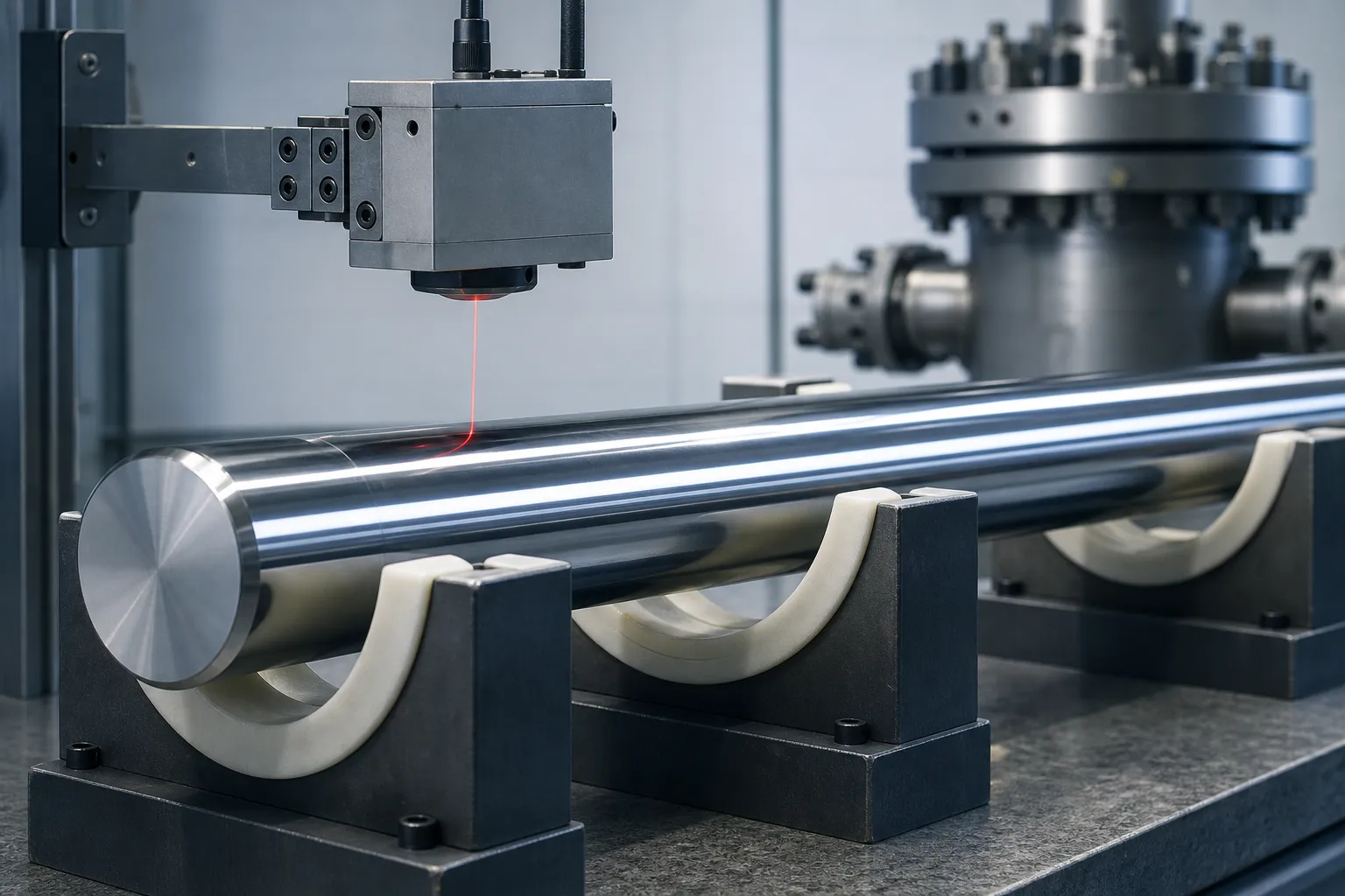
At the top of the rod string sits the polished rod — the one member of the API 11B family whose surface is a dynamic sealing surface. It passes through the stuffing box at the wellhead on every stroke, riding inside the polished rod packing, and its name describes the requirement: a straight, smooth body that lets the seal do its work. Every other rod in the string can carry cosmetic marks within limits; on the polished rod, a mark or a bend has a direct functional consequence at the surface.
The failure chain is what makes straightness an economic input rather than a cosmetic one. A bowed polished rod does not simply run crooked: on each stroke it sweeps laterally inside the packing, tihendi ühe külje laadimine ja teise lõdvestamine. Pakend kulub ebaühtlaselt, kompenseerimiseks tuleb tihendi kokkusurumist suurendada, hõõrdumine ja varda pinna kulumine tõusevad koos, ja kaevupea jõuab tihendi-asendamise tsüklile, mis on palju lühem, kui sirge varras võimaldaks. Sirgus ja pinnaviimistlus toimivad koos – ühe taastamine ilma teiseta ei taasta tihendi eluiga.
Sirgendava toorikuna, poleeritud varras on seega perekonna kõige kaitstum liige. Kontaktmaterjalid, toe puhtus ja kinnitusreeglid on seatud vastu tihenduspinda, mitte struktuurne keha — tööriistade küsimused sisse pinnakaitsetööriistad sirgendamiseks on õige alustamise kontrollnimekiri, kohaldada täie rangusega. Mõõtmine eristab kahte tsooni: kogu keha profiil, asjakohane käsitsemise ja väsimuse seisukohalt nagu iga ridva puhul, ja pakkimisreisi tsoon, kus vastuvõtmise arutelu algab pigem kõige tihedamast ribast kui kõige lõdvemast. Tarnijad kataloogivad poleeritud vardad oma tootesarjana 11B perekonnas, oma otsa- ja pinnavariantidega — masinaprojekt peaks neid samamoodi käsitlema: sama parandusfüüsika, rangem kontaktkaart.
Dispositsioon on nii hooldusotsus kui ka geomeetriline otsus. Poleeritud varras, millel on korrosioonisüvendid või täkked liikumistsoonis, ei sobi sirgendamiseks – tihend ei hooli sellest, et keskjoon on nüüd sirge. Geomeetriliselt terve, kuid vigastatud tihendiga varras tuleb enne uuesti sirgeks laskmist ja uuesti kasutuselevõttu kontrollida pinna kogumise suhtes. Vardatööd tihendavatele kauplustele, praktiline jaotus on lihtne: kere sirgendamise võime laieneb loomulikult ka poleeritud varrastele, kuid ainult ülaltoodud kontaktkaardi ja mõõtmisplaaniga, mitte tavaliste imemisvarraste retsepti ülekandmise teel.
Kaardistage kogu toorik
Ettepanek peaks identifitseerima iga juhitava funktsiooni ja selle teljesuunalise asendi:
- tavaline varda korpus;
- keha läbimõõt ja igasugune kate või kulumiskindel töötlus;
- ärritunud või sepistatud otsaosa;
- üleminek kehalt ärritusele;
- mutrivõti ruut või mutrivõti lamedad;
- pin õlg;
- väline tihvti keerme;
- pin nägu;
- tuvastamine, klassi ja jälgitavuse märgid;
- paigaldatud varraste juhikud või juhikukohad, kui olemas;
- korrosioon, kandma, kasutatud varraste täkked või varasemad remonditsoonid;
- haakeseadise olek: eemaldatud, lõdvalt kaitstud või väljaspool sirgendamise ulatust.
NOV's public sucker-rod services sheet separates full-length visual inspection of the body, tihvti otsad, niit ja nägu. See on õige mõtteviis sirgumiseks: varras ei ole vastuvõetav ainuüksi seetõttu, et keskmise korpuse näidik on pärast töötlemist madalamal.
Külmutage tootmise või taastamise etapp
Uus varras enne kuumtöötlust
Materjal võib korrektsioonile paremini reageerida, kuid hilisem kuumtöötlemine võib moonutusi uuesti tekitada. Siin peab sirgendamine toetama järgmist tootmisoperatsiooni ega asenda lõppkontrolli.
Pärast kuumtöötlust
SLB teatab, et tema imivardad on toodetud, kuumtöödeldud ja testitud. Selles etapis, hinne, kõvadus, jääkpinge ja pragude tundlikkus muutuvad korrektsioonisisenditeks. Töötlemata batoonivarust valmistatud retsepti ei saa ilma kinnitamiseta üle kanda.
Enne lõplikku lõppu või pinnaviimistlust
Kui protsessi planeerimine lubab, järelejäänud laojääk või hilisem viimistlus võib vähendada märgistamisriski ja taastada funktsionaalsed pinnad. Allavoolu toimimine peab kasutama ühilduvat tugipunkti ja ei tohi uuesti luua kurvi.
Kaetud või viimistletud uus varras
SLB kirjeldab korrosiooni- ja kulumiskindlad varraste katted karmides tingimustes. Viimistletud või kaetud varras vajab heakskiidetud kontaktmaterjali, puhtusestandard ja protsessijärgne pinnakontroll. Kattekiht ei ole ohverdatav rullrada.
Kasutatud varraste taastamine
NOV loetleb avalikult koristamise, magnetic particle inspection, electromagnetic inspection, full-length visual inspection, coupling removal, dimensional verification, demagnetization and grading for new and used sucker rods. Straightening belongs inside that inspection route; it cannot replace it.
Measure the Full Length Without Measuring Support Sag
Pikad peenikesed vardad kalduvad oma raskuse all kõrvale. Kui tugivahed, üleulatuvus või orientatsiooni muutused, mõõdetud profiil muutub ka siis, kui materjal pole seda teinud. Seetõttu vajab täispikk süsteem külmutatud tugimudelit.
Mõõtmiskava peaks määratlema:
- aksiaalne päritolu ja varda suund;
- toetuste arv, vahekaugus, kõrgus ja kontaktjõud;
- vaba oleku või kontrollitud toega sirguse määratlus;
- täispikk kereprofiil kontrollitud aksiaaljaamades;
- kohalik keha läbimõõt, ristlõikepindala või vajadusel kulumiskontroll;
- pin-ots, õlg, niidi ja näo kontroll eraldi funktsioonidena;
- lubatud välistamiskaugus häiritud üleminekute ümber;
- katte või pinnaseisundi mõju andurile;
- temperatuuri, puhastus- ja stabiliseerimisseisund;
- korratavus pärast mahalaadimist, pöörlemine ja uuesti kinnitamine;
- correlation with the customer's inspection and grading system.
Lugege võlli sirgus vs väljavool vs TIR enne teatatud väärtuse valimist. Statsionaarne toetatud profiil, pöörlev väljajooksu jälg ja vaba oleku sirguse tulemus ei ole omavahel asendatavad.

*Tehnilise kontseptsiooni illustratsioon kaitstud tihvtiotstega mitmest jaamast kehamõõtmisest. See ei ole ette nähtud gabariidi paigutus. Tegelik tugivahe, longus kompensatsioon, anduri jälgede ja lõppfunktsioonide kontrollimiseks on vaja varda spetsifikatsiooni ja kliendi gabariidi korrelatsiooni.*
Eraldage paindumine kahjustustest ja seadistusvigadest
| Vaadeldav signaal | Võimalik põhjus | Nõutav marsruut |
|---|---|---|
| Sile pikalaineline profiil, mida korratakse pärast uuesti kinnitamist | Globaalne kehavibu | Valideeritud rulli- või presskorrektsiooni kandidaat |
| Terav lokaalne muutus ühes kohas | Kink, mõju, korrosioonikadu või kohalikud kahjustused | Kontrollige ja suunake projekteerimisse või lükake tagasi; ärge keskmistage seda globaalseks kurviks |
| Profiilide muudatused tugivahedega | Isekaaluline longus või ebastabiilne tugimudel | Külmutage tugiseisund ja korrake mõõtmist |
| Jälgi muutusi pärast puhastamist | Skaala, õli, pinnakatte ladestus või praht | Puhastage ja kvalifitseerige mõõtepind |
| Kere on stabiilne, kuid üks tihvti ots tundub ekstsentriline | Sepistatud ots, õla või keerme telje probleem | Kontrollige lõppfunktsiooni; keha sirgendamine ei pruugi seda parandada |
| Kõrge signaal häiritud ülemineku lähedal | Mõeldud sektsiooni vahetus, lokaalne jäikus või vormimisviga | Kasutage funktsioonipõhist välistamist ja tehnilist ülevaadet |
| Pinna süvendi või pragude tähis langeb kokku paindega | Korrosiooni- või väsimuskahjustused | Kontrolli/tagalükkamise tee enne korrigeerimist |
| Varras on sirge, kuid ridva tõstmise jõudlus jääb kehvaks | Sidumine, juhend, torud, joondus, laadimise või hea seisukorra probleem | Hinnake kogu varraste nööri ja tehistõstesüsteemi |
Sirgendamine võib muuta geomeetriat. See ei suuda taastada korrosiooni tõttu kaotatud metalli, eemaldage väsimuspraod või tõestage, et kasutatud varras sobib teise hooldustsükli jaoks.
Ehitage enne sirgendajat kontrollvärav
Uute varraste jaoks, värav peaks kinnitama materjali klassi, kuumtöötlemise olek, pinna seisukord, jälgitavus ja lubatud parandusstaadium.
Kasutatud varrastele, värav on piiravam. NOV avalikud nimekirjad:
- puhastamine ja haavlipuhastus või lõhkamine;
- keha täispikk visuaalne kontroll, tihvti otsad, niit ja nägu;
- magnetic particle inspection;
- electromagnetic inspection;
- laseri ristlõike pindala või välisläbimõõdu kontrollimine;
- siduri eemaldamine ja ülevaatus;
- demagnetiseerimine;
- klassifitseerimine ja värvikoodid vastavalt API või kliendi nõudmistele.
The exact inspection sequence and acceptance values belong to the customer's applicable standard and procedure. Masin peaks läbima kontrollioleku, ei eelda, et iga lahtrisse sisenevat painutatud varda on ohutu parandada.
Kaitske tihvtide otsi ja pinda
Vaikimisi No-Roller, No-Toetamine või No-Press Zones
- välised tihvtide keermed;
- pin nägu ja õlg;
- mutrivõtmed või mutrivõti ruut;
- ärritunud või sepistatud ots;
- üleminek kehalt ärritusele;
- tunnus- ja hindemärgid;
- varraste juhikud või juhiku kinnitustsoonid;
- heakskiitmata kattekiht, kaetud või spetsiaalselt töödeldud pinnad;
- korrosiooniaugud, praod, torked, kandma tasapindu või löökkahjustusi;
- haakeseadis ja keermekaitse, välja arvatud juhul, kui käsitsemiskonstruktsioon seda selgesõnaliselt toetab.
Potentsiaalselt heakskiidetud kontakttsoonid
- kontrollitud läbimõõdu ja pinna seisukorraga puhastatud tavalised vardakere maad;
- lõpetamata kehaosa enne lõplikku pinnatöötlust, kui protsessiplaan seda võimaldab;
- laiad poleeritud rullid või vahetatavad sisetükid, mis on valideeritud kontaktrõhu ja märgistuse jaoks;
- kontrollitud tugipunktid, mis on valitud eemal üleminekutest ja teadaolevatest kahjustustest.
Ohutu kaart tuleks siduda ridva perekonnaga, pikkus, hinne, katmine, lõppkujundus ja läbivaatamine. Ühele ponivardale vastuvõetav tugi võib kukkuda teise pere sepistatud ülemineku- või juhtkohale.

*Tehnilise kontseptsiooni illustratsioon kuuest siledast rullikust, mis toimivad tavalisel varda korpusel, samal ajal kui sepistatud tihvt ja niit jäävad rullikassetist välja. See ei ole universaalne masina paigutus. Rulli geomeetria, kompenseerida, kontaktpinge ja materjali reaktsioon nõuavad proovi valideerimist.*
Valige veakaardilt parandusmeetod
Mitme rulliga sirgendamine
Ristrullimise või astmelise rullimise süsteem võib sobida pikalaineliseks kere kumerduseks ja pidevaks töötlemiseks, kui varda korpus tagab stabiilse, heakskiidetud rullirada. Boyu Petro turustab avalikult naftaväljade torude rull-sirgestusseadmeid, korpus, puurtoru, terastoru ja imivardad. See kinnitab varustuse kategooriat; see ei kehtesta universaalset imipulga retsepti ega kontrolli tulemust.
Rullide kontseptsioon ikka nõuab:
- õige rulligeomeetria tahke varda korpuse jaoks;
- kontrollitud nihked ja ajami seisukord;
- tihvtide otste ja sepistatud üleminekute kaitse;
- pinna märgistamise ja katmise katsed;
- sisenemise ja väljumise tugikontroll;
- välja antud täispikk kinnitus;
- uute ja kasutatud varraste kontrollimise marsruut.
Punktivajutuse sirgendamine
Mõõdetud survemarsruuti võib kaaluda kindlaksmääratud kohaliku kehakõveruse jaoks, kui on võimalik luua ohutud toed ja pressimispunkt. See vajab jõu- ja nihkepiiranguid, kaitstud kontaktide kaart, tagasilöögiloogika ja täielikult vabastatud ümbermõõtmine. See ei sobi terava murdumise korral, pragude märge või kahjustatud ots ainult seetõttu, et viga on lokaalne.
Lugege presssirgendamine vs rullsirgendamine üldise meetodi võrdluse jaoks, seejärel rakendage imivarda kontroll- ja kontaktväravad.
Keeldu, Asenda või hinda ümber
Parandus peaks lõppema, kui vardal on heakskiitmata pragude märge, liigne korrosioon või sektsiooni kadu, tõsine kink, kahjustatud tihvt/niit/nägu, ebakindel hinne, ebasobiv katte seisukord, vastuvõetamatu eelnev remont või muu tingimus, mis ei kuulu kinnitatud tagasinõudmisprotseduuri.
Kujundage vabastatud osaga suletud ahel
Aktsepteeritud väärtust tuleb mõõta pärast seda, kui varras lahkub aktiivsest rullist või presskoormusest.
- Tuvastage varraste perekond, pikkus, hinne, lõppkujundus ja uus/kasutatud olek.
- Kinnitage sissetuleva kontrolli paigutus ja eemaldage vajaduse korral liitmikud.
- Puhastage korpus ja kaitske tihvtide keermeid ja nägusid.
- Laadige varras juhitavale täispikale tugisüsteemile.
- Mõõtke kereprofiili ja eraldage lõppfunktsiooni või kohalike kahjustuste signaalid.
- Klassifitseerige viga ja valige rull, vajutage, tagasilükkamise või inseneriülevaatuse tee.
- Rakendage ainult kinnitatud keha tsoonile määratud piiritletud parandust.
- Vabastage ja stabiliseerige varras täielikult.
- Mõõtke sama profiili uuesti samadel tugitingimustel.
- Korrake ainult iteratsiooni jooksul, jõudu, nihke ja pinna piirid.
- Tehke nõutav protsessijärgne visuaal, mõõtmete ja NDT kontrollid.
- Hinne, mark, jälgige ja suunake ritv vastavalt kinnitatud kvaliteediprotseduurile.
Kontroller peaks salvestama nii geomeetria tulemuse kui ka kvaliteedi dispositsiooni. Roheline sirguse tulemus ei tohi ületada NOK keerme, pinna- või NDT tulemus.
Konfigureerige tootmis- või taastamislahter
| Lahtri funktsioon | Nõue imemisvardale |
|---|---|
| Identifitseerimine | Rod perekond, hinne, pikkus, lõppkujundus, kate ja uus/kasutatud olek |
| Saabuv ülevaatus | Puhastamise olek, visuaalne tulemus, mõõtmetega tulemus, NDT staatus ja paigutus |
| Käitlemine | Pika voodi tugi ilma lohisemiseta, tihvti löök või keerme kahjustus |
| Mõõtmine | Täispikk kereprofiil koos külmutatud tugi-/vajumismudeli ja lõpp-funktsiooni eraldamisega |
| Parandus | Kaitstud mitme rulliga või mõõdetud pressi marsruut piiratud seadistustega |
| Lõppkaitse | Keermekorgid või kontrollitud käsitsemine väljaspool korrektsioonitsooni |
| Kontrollimine | Täielikult vabastatud profiil pluss nõutavad kere/otsa/pinna kontrollid |
| Kvaliteetne marsruutimine | OK, ümber mõõta, piiratud ümbertöötamine, reegel, tehniline ülevaatus või tagasilükkamine |
| Jälgitavus | Varda ID, retsept, ülevaatuse olek, esialgne/lõplik profiil, parandusajalugu ja häired |
Automatiseerimine võib sisaldada konveiereid, jalgsi talad, automaatne lõpu tuvastamine, puhastamine, lasermõõtmine, rulli reguleerimine, NDT integreerimine ja liigitamine. The required configuration depends on rod-family mix and the customer's existing reclamation line; seda ei tohiks tuletada lati sirgendaja üldisest spetsifikatsioonist.
Kinnitage esindusvarrastega
Näidisprogramm peaks sisaldama tegelikku tootmismahtu:
- minimaalne ja maksimaalne ridva või poni ridva pikkus;
- kõik hõlmasid keha läbimõõtu ja otste geomeetriat;
- materjali klassid ja kuumtöötlemise olekud;
- kaetud ja katmata variandid ainult siis, kui mõlemad on hõlmatud;
- realistlikud pikalainelised vibud ja teadaolevad kohalikud NOK tingimused;
- uued ja kasutatud vardad eraldi valideerimisrühmades;
- erinev korrosioon, kasutatud varraste kulumis- ja puhastustingimused;
- korduv laadimine, pöörlemis- ja tagasitõmbekatsed;
- niit, nägu, õlg, kehapinna ja NDT kontrollproovid;
- kliendi mõõtmise ja hinde korrelatsioon.
Vastuvõtuaruanne peaks sisaldama proovide arvu, varda identifitseerimine, ülevaatuse olek, tugi seadistamine, mõõtmise korratavus, alg- ja lõppprofiilid, rulli või pressi seaded, iteratsioonid, pinna leiud, NDT tulemused, hindetulemus ja välistatud tingimused.
Lugege sirgendamise proovi katse ja vastuvõtmine üldise FAT/SAT tõendite struktuuri jaoks. Imenvarda projektile tuleb lisada kehtiv kontrolli- ja taastamisprotseduur.
Mida sirgendusmasin ei tõesta
Madalama keha painde näit iseenesest ei tõesta:
- vastavus API Spec 11B või kliendi tagasinõudmise standardile;
- taastunud väsinud eluiga;
- pragude eemaldamine, korrosiooniaugud, kulumine või sektsiooni kadu;
- vastuvõetav tihvti niit, õla või näo seisund;
- õige siduri koostis või ühenduse terviklikkus;
- compatibility with a particular well's load and corrosion environment;
- vastuvõetav vardajuhik, torude või varraste süsteemi seisund;
- iga kasutatud varda ohutu taaskasutamine.
API identifitseerib ametlikult Spec 11B 28. väljaande kui praeguste imevarraste ja varrastega seotud toodete spetsifikatsioonid. Ostja ja kvaliteediamet peavad esitama vastava väljaande, projekti vastuvõtuväärtused ja kontrollimise kord. StraighteningTech ei tohiks välja mõelda ega ümber sõnastada ligipääsmatuid standardpiiranguid.
Imikuvarda ettepaneku jaoks vajalik teave
Palun esitage:
- ridva ja poni-varraste joonised koos revisjoniga;
- kohaldatav standard ja kliendi kontrolli/taastamise kord;
- keha läbimõõt, pikkusvahemik, segi/lõpu geomeetria ja keermedetailid;
- materjali klass, kõvadus ja kuumtöötlemise olek;
- katmine, juhised ja pinnakaitse nõuded;
- uus tootmine või kasutatud taaskasutamise etapp;
- sissetulev puhastus, visuaalne, mõõtmetega ja NDT marsruut;
- esialgne kereprofiili jaotus ja kohalikud NOK näited;
- sirguse või läbijooksu määratlus, tugiseisund ja sihtmärk;
- heakskiidetud ja keelatud kontakttsoonid;
- pin niit, nägu, õlgade ja keha aktsepteerimise nõuded;
- tootmismaht, perekonna segu ja ülemineku sagedus;
- laadimine, mahalaadimine, haakeseadise-eemaldamise ja otsakaitse meetod;
- jälgitavus, klassifitseerimise ja andmete ekspordi nõuded;
- esinduslikud OK ja NOK proovid.
StraighteningTech saab seejärel mõõtmismudeli välja töötada, kaitstud kontaktide kaart, meetodi valik, masina konfiguratsioon, määratletud varraste perekonna proovikatseplaan ja aktsepteerimise tõendid. Tulemuseks on kontrollitud imemisvarraste protsess – mitte üldine lubadus lasta painutatud naftavälja varras läbi varda või toru sirgendaja.