
Õlipuuritorude sirgendamise lahendused
Nafta puurimistoru on naftapuurimise põhivarustus, ning selle sirgus ja koaksiaalsus mõjutavad otseselt puurimise tõhusust ja ohutust. Meie sirgendamise lahendus kasutab suure täpsusega intelligentseid sirgestamisseadmeid, mis on varustatud ülitäpse lasermõõtesüsteemiga, et tagada igasuguste õlipuuritorude sirgendamise täpsus ja koaksiaalsus vastavad API standardite nõuetele., mis parandab oluliselt puurimistööriistade kasutusiga ja puurimise efektiivsust.
Õlipuuritoru kasutamine

Standardne puurtoru
Standardne puurtoru on naftapuurimisel kõige sagedamini kasutatav puurimistööriist ning see peab tagama suurepärase koaksiaalsuse ja sirguse, et parandada puurimise efektiivsust.
Rakendus:
- API standardne puurtoru
- süvakaevude puurvarras
- Suunatav puuraugu puurvarras
- Horisontaalne puuraugu puurvarras
Tehnilised parameetrid:
- Koaksiaalsus: ≤0,08 mm/m
- Sirgus: ≤0,2 mm/m
- Ümarus: ≤0,1 mm
- Tootmise efektiivsus: 15-20 tk/h
Spetsiaalne puurtoru
Spetsiaalseid puurtorusid kasutatakse erilistes geoloogilistes tingimustes ja keerukates töökeskkondades, mis nõuavad kõrgemaid materjaliomadusi ja töötlemise täpsust.
Rakendus:
- ülisügav kaevu puurimine
- Väävlit sisaldav O-kaev
- Kõrgsurve kaevu puurimine
- Kõva põranda puurimine
Tehnilised parameetrid:
- Koaksiaalsus: ≤0,05 mm/m
- Sirgus: ≤0,15 mm/m
- Ümarus: ≤0,1 mm
- Tootmise efektiivsus: 10-15 tk/h

Tööriistade liigeste painded ja kogu toru sirgendamine
Puurtoru mõlemas otsas olevad tööriistade ühendused on hõõrdkeevitatud, paksuseinalised sepistatud sektsioonid, mis kannavad API-ühendusi – niigi jäiga sõlme jäigeim osa. Praktikas ei paindu nad peaaegu kunagi üksi: kui ülevaatuslipud jooksevad välja või painduvad tööriista ühenduskohas, tegelik kõverus elab tavaliselt toru korpuses keevisõmbluse ülemineku lähedal või korpuse ja vuugi liideses, ja korrektsioon tehakse kogu torule, kui liitekohad on paigas. Töökoja mõistes tähendab tööriistaühenduse sirgendamine seega terve toru sirgendamist, mõõdetuna liigestest.
See mõõtmispunkt on oluline. Ühenduskohas võetakse vastu sirgendatud puurtoru: ühenduskeerme telje ja toru korpuse telje vaheline väljavool on see, mis nööris jookseb, seega on ülevaatuse lähtepunkt ühenduskoht isegi siis, kui press mõjutab keha meetrite kaugusel. Parandustee järgib meie artiklis kirjeldatud press-vers-roll loogikat presssirgendamine vs rullsirgendamine võrdlus, keermekaitsetega, mis on paigaldatud enne kontakti ja tugivahed, mis on määratud mõõdetud paindekaardilt, mitte toru pikkuse harjumustest.
Jada on loo teine pool. Naftaväljade ülevaatuse töövõtjad kirjeldavad taastamisvooge, mille puhul on esikohal õgvendamine, enne puhastamist ja sellele järgnevat seinapaksust, triivi ja pragude uuringud – geomeetria tuleb taastada, enne kui need kontrollid annavad sisulisi tulemusi (teatatud teenuste järjestuse kirjeldused puurtorude korrastamise pakkujatelt). Toru all olevatele raskematele BHA liikmetele, parandusloogika eskaleerub jõuklassis: vaata meie puurkrae sirgendamine ja raske puurtoru sirgendamine lehed üleminekutsooni ja kraeperekondade jaoks.
Kaks praktilist reeglit hoiavad tööriistaliigenditega seotud sirgendamise probleemidest eemal. Esiteks, kaitske ühendusi enne midagi muud: niidikaitsed jäävad mõõtmise ja vajutamise ajal peale, ja ei mingit toetust, rull või klamber kannab kunagi õlale, keerme või pöörleva õla tihend – ühendus on toru kõige väärtuslikum ja vähem parandatav omadus. Teiseks, käsitlema hõõrdkeevistsooni kui oma kontrolliobjekti: keevisõmbluse lähedusse koondunud painutus peaks käivitama üleminekupiirkonna pragude kontrolli enne mis tahes pressimistsüklit, kuna see tsoon kannab nii keevisõmbluse jääkpingeid kui ka sektsioonimuutust, mis koondab tööpainutust. Toru, mis läbib sirguse kontrolli, kuid millel on kahjustatud ühendus või kontrollimata keevisõmbluse anomaalia, ei ole taastatud – selle tagasilükkamine on ainult raskendatud.
Twisted Pipe Is Not Bent Pipe — the Twist-Off Judgment
Drill pipe accumulates two different kinds of geometric damage, and only one of them belongs on a press. A painutada is deviation in a single plane — the tube reads straight from two perpendicular viewpoints and curved from the others. A väänata is permanent angular displacement around the pipe’s own axis: scribe a longitudinal line down a twisted joint and the line rotates as it travels — one cross-section has permanently rotated against its neighbors. The distinction matters because the two conditions come from different events and leave different damage behind.
Permanent twist is usually an accident record: twist-off events, where the string’s stored torsional energy releases at parting and winds the pipe beyond yield, plus stuck-pipe back-offs and the sustained torque of directional work. By the time the twist is visible, the affected length has already been loaded past yield in torsion — a metallurgical fact, not a geometry problem: no press cycle unwinds it, and rotating the section back cold would add a second plastic episode on top of the first.
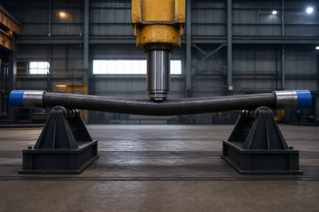
This is why press straightening, as a process, declines the job. A straightening press superimposes controlled single-plane bending; twist correction would instead require controlled torque about the axis across the twisted length — a different machine and loading mode — while the yield history that produced the twist remains in the steel either way. The judgment that does apply runs:
- Quantify the twist first. Mark or measure the angular reference along the joint — how many degrees over what length — before any decision, the same measure-first discipline that governs bending.
- Treat visible permanent twist as a material flag. It marks a length that has already yielded once in service — a condition for the inspection standard to evaluate, not a shape to correct.
- Check the connections specifically. A joint that took twist concentrates consequences at the rotary shouldered connections, where make-up reference and shoulder sealing are compromised independently of the body — damage that routes to re-machining or replacement decisions, mitte ajakirjandusele.
- Route the verdict to the inspection standard. Whether a twisted joint is downgraded, restricted or condemned is decided under the governing inspection practice for drill stem elements — the framework mapped in our API straightness standards overview — not in the shop.
The practical consequence for reconditioning flow: twist is screened out at incoming inspection, before the joint is ever scheduled for press time. That sequencing — classify, then correct only what classification releases — is the organizing principle of our drill pipe reconditioning workflow article. A shop that discovers twist after straightening has wasted press time on a joint that was never a candidate.
One borderline case deserves honesty: a joint can carry both a bend and a mild residual twist, and the bend alone is legitimately correctable. Correct only what measurement defines — plane-by-plane bend correction to the connection-axis datum, with the twist documented and routed to the inspection decision — never “improved” by pressing harder in a diagonal plane.
The RSC Thread Axis Is the Straightness Datum
Ask where straightness is measured on a drill pipe joint and the wrong answer is the most common one: the outside surface of the tube. A chalk line along the OD can read straight while the joint still runs out in the string, and a joint with a visible body bow can run true — because the pipe’s functional axis is not its skin. It is the axis established by the rotary shouldered connections at both ends. The RSC thread axis is the datum the string actually rotates about, and every straightening measurement that matters is taken against it.
The reasoning is mechanical. Teenistuses, the joint’s position in the drill string is defined entirely by its two connections: shoulders seat, threads engage, and the next joint’s axis continues from the connection axis, not from the mid-body OD. What the rig experiences as “crooked pipe” is eccentricity between those connection axes and the tube between them. A body-straightening pass judged on surface lines can leave that eccentricity untouched — the tube looks better and the string vibrates exactly as before.
Measurement practice follows the datum:
- Simulate the thread axis at both ends. Thread-mounted arbors, expanding mandrels or precision centering in the connection bore stand in for the axis the threads define, and runout is read off the tube body against that simulated axis.
- Or invert the reference. With the joint supported on the connection datum surfaces, body runout is measured directly along the tube — support geometry substitutes for arbors when they are not available, at some cost in setup rigor.
- Read at defined stations, not at the worst-looking spot. A runout profile along the body — the multipoint logic described in our multipoint shaft measurement article — is what turns “it looks straight” into a number the certification can carry.
The connection-inspection world already maintains a mature gauge ecosystem for RSC geometry — thread single-element and gauging practice for taper, lead and form — and straightening acceptance should be understood as one branch of that same connection-defined metrology. The gauges certify the connection; the runout check certifies the body against the connection’s axis; together they answer the only question the string asks: does this joint run true about the axis its threads define?
On the press, the datum has two operational consequences. Supports and press points are chosen so the correction acts on the body without ever loading a connection, and the post-correction verification is taken on the connection-axis datum before the joint is released — shop-floor acceptance and string-level acceptance stay the same measurement, as outlined for tubular repair work in our drill pipe reconditioning workflow. A straightening record that shows body runout measured to the RSC axis is the one a recertification file can defend; anything measured to a surface line is geometry documentation, not acceptance.
Õlipuuritoru sirgendamise lahenduse protsessi video
Toote omadused õlipuurtoru sirgendamiseks
- Testi täpsuse tagamiseks, kasutage katseseadmete ehitamisel ja töötlemisel ülitäpset nihkeandurit.
- Varustatud ülitäpse asendikontrolli laadimissüsteemiga, et parandada joondamise täpsust.
- Erinevate komponentide koordineerimine ja haldamine, et lühendada sirgendamise protsessi.
- Täiuslik ebanormaalse olukorra häireteave seadmete hoolduse hõlbustamiseks.
- on 16g mälukaart töötlemisinfo salvestamiseks, reserveeritud sideühendus hostarvutiga.
- Kiiresti vahetatavad tööriistad ja kinnitused, parameetritega reguleerimine ja ümberlülitamine, automatiseeritud tööriista seadistamine.


