
Shaft straightening is not one universal machine process. A plain bar, stepped motor shaft, flanged axle, geared transmission shaft and long hollow drive shaft can all appear “bent,” but they do not share the same functional datum, safe contact zones, measuring method or correction response.
StraighteningTech evaluates shaft-straightening projects from the workpiece drawing, sissetulev deformatsioon, process stage and acceptance method. This hub compares established shaft-straightening architectures and routes an inquiry; it does not state that every listed workpiece family or machine architecture is within our current verified supply range. A project-specific capability, cycle time and equipment configuration may be specified only after drawing review, mõõtekorrelatsioon, representative testing and released acceptance results.
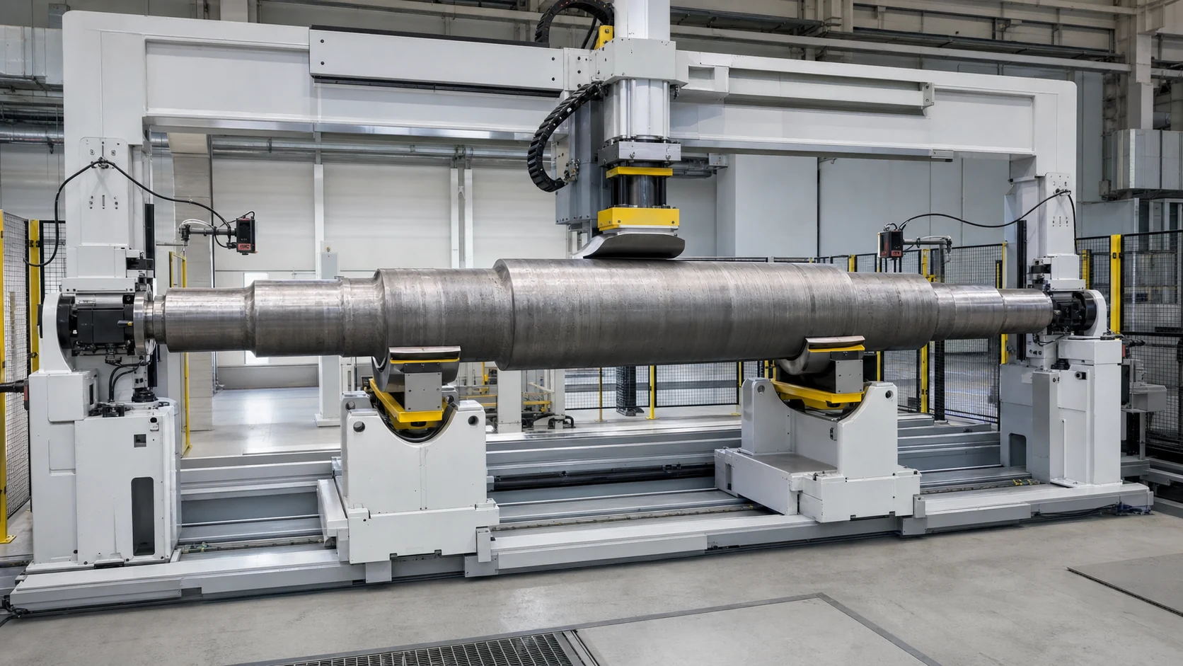
*Insenerikontseptsiooni illustratsioon. It does not represent a delivered machine, customer project, verified sensor configuration, accuracy or cycle time.*
Find the Right Route for Your Shaft
Start with geometry and function. The useful question is not only “What is the shaft diameter?” but “Which features define the axis in the next machining or assembly operation?”
| Shaft Family | Typical Features | Primary Engineering Risk | Likely Starting Method |
|---|---|---|---|
| Plain shaft or bar blank | Constant diameter, unfinished surface | Long-span support and multiple bends | Roller straightening or point press, depending on length and tolerance |
| Stepped motor or pump shaft | Laagripäevikud, rotor seat, õlad, võtmeava | False runout from the wrong datum; marks on finished journals | Automatic measuring and point press straightening |
| Gearbox or splined shaft | Ajakirjad, hammasrattad, splainid, radiaalsed augud | Functional runout, tooth measurement and crack-sensitive zones | Multi-point measuring and controlled point correction |
| Axle or flanged shaft | Long body, äärik, splain, niit | Stable rotation, flange datum and asymmetric stiffness | Dedicated support, rotation and point correction |
| Worm, lead or ball screw | Threaded functional section, ajakirjad, slender span | Probe disturbance, thread damage and springback | Drawing-defined datum realization—such as approved journals, centers or a functional gauge—with protected correction zones |
| Camshaft or eccentric shaft | Lobes, journals and changing section | Irregular measuring surfaces and local stiffness changes | Feature-aware measurement and model-specific correction |
| Hollow drive shaft or tube | Õhuke sein, keevisõmblused, yokes or flanges | Collapse, mõlkimine, phase relationship and balance interaction | Tube-protective tooling; straightening and balancing treated separately |
| Steering rack or asymmetric shaft | Smooth journals plus toothed rack | Mitteümmargune sektsioon, gear function and restricted press zones | Profile-aware support, measurement and correction |
If the part combines several families, the most sensitive functional feature controls the solution. A hollow splined drive shaft, näiteks, cannot be treated as a simple round bar.
These routes are screening hypotheses, not universal assignments. Joonistus, protsessi etapp, permitted contact zones and representative trials decide the final method.
Define the Correct Measurement Before Straightening
Sirgus, ringikujuline väljavool, total runout and shop-floor TIR are related but not interchangeable. The drawing must identify the governing ISO or ASME system and edition. Straightness is a form control and does not use an external datum reference. Circular and total runout are evaluated relative to a specified datum axis; the physical support and machine rotation axis must be shown to realize that datum.
| Drawing Requirement | What Must Be Agreed | Why It Matters to the Machine |
|---|---|---|
| Axis or surface straightness | Controlled line, tolerance zone and evaluation length | Defines measuring positions and correction objective |
| Ringikujuline jooks | Kuupäeva telg, sondi pind, axial station and one full rotation | Controls the reading at the specified circular section |
| Täielik läbijooks | Kuupäeva telg, controlled surface, probe path and rotation rule | Extends evaluation across the specified surface |
| Shop-floor TIR | Datum, station or path, rotation and max–min reading rule | TIR must not be assumed to mean GD&T total runout |
| Journal-to-datum-axis relationship | Exact drawing characteristic, datum features and controlled journals | Avoids using “coaxiality” as an undefined shop-floor substitute |
| Gear or spline function | Pitch-diameter or functional gauge method | Smooth journal measurement alone may miss a functional error |
| Final assembly behavior | Laager, pitsat, sidumine, rotor or gear interfaces | Prevents optimizing a convenient dimension that does not control the assembly |
Enne tsitaati, mark every support, measuring and pressing zone on the drawing. Also mark keyways, sooned, niidid, õliaugud, cross holes, lobes, hambad, thin walls, keevisõmblused, coatings and final-ground surfaces that must not be contacted without approval.
For results near the tolerance boundary, the machine and customer methods should document the same measurand and measurement model, together with the applicable uncertainty and conformity decision rule.
Point Press or Roller Straightening?
The choice depends on geometry, process stage and acceptance method—not on a generic preference for one machine type.
| Otsustegur | Automatic Point Press Straightening | Roller or Through-Feed Straightening |
|---|---|---|
| Best starting fit | Discrete stepped or feature-rich shafts | Constant-section bars, tubes and shaft blanks |
| Mõõtmine | Rotation at defined journals with one or more probes | Offline or integrated straightness/runout measurement |
| Parandus | Local controlled over-bending at an approved axial and angular position | Repeated bending through arranged rolls |
| Feature protection | High flexibility for no-press and no-support zones | Limited when steps, hammasrattad, flanges or finished features enter the rolls |
| Mudeli vahetus | Retsept, support and tooling changes | Roll setting, guide and line setup changes |
| Typical advantage | Closed-loop correction linked to the measured bend | Continuous processing and efficient handling of uniform material |
| Main validation need | Springback model, contact marks and maximum correction limits | Roll geometry, surface protection and full-length result |
Some production routes use both methods at different stages. A constant-diameter blank may be roller-straightened before machining, while the finished stepped shaft receives datum-based point correction after heat treatment or grinding.
Closed-Loop Automatic Shaft Straightening Process
For a feature-rich shaft, the common engineering sequence is measure, arvutada, correct and remeasure. The exact sensors, toetab, press force and automation modules are selected for the real part family.
The video shows one automatic small-shaft material-flow and press-straightening concept. It demonstrates visible equipment structure and sequence only; its public metadata does not establish a motor-shaft identity, anduri tüüp, jõudu, tolerance or cycle time.
1. Identify the Part and Select a Validated Recipe
The proposed recipe defines the datum realization, tugipositsioonid, mõõtejaamad, lubatud parandustsoonid, target characteristic and maximum correction limits. Barcode, DMC or production-order selection is an optional architecture that may reduce mixed-model errors when included in the confirmed project scope.
2. Laadige, Support and Rotate the Shaft
Käsitsi laadimine, kandik, konveier, robot or gantry are candidate handling architectures rather than a default scope. The workpiece must rotate stably in a verified support arrangement that realizes the specified datum. Keskused, V-toed, rollers and the machine rotation axis are not automatically interchangeable.
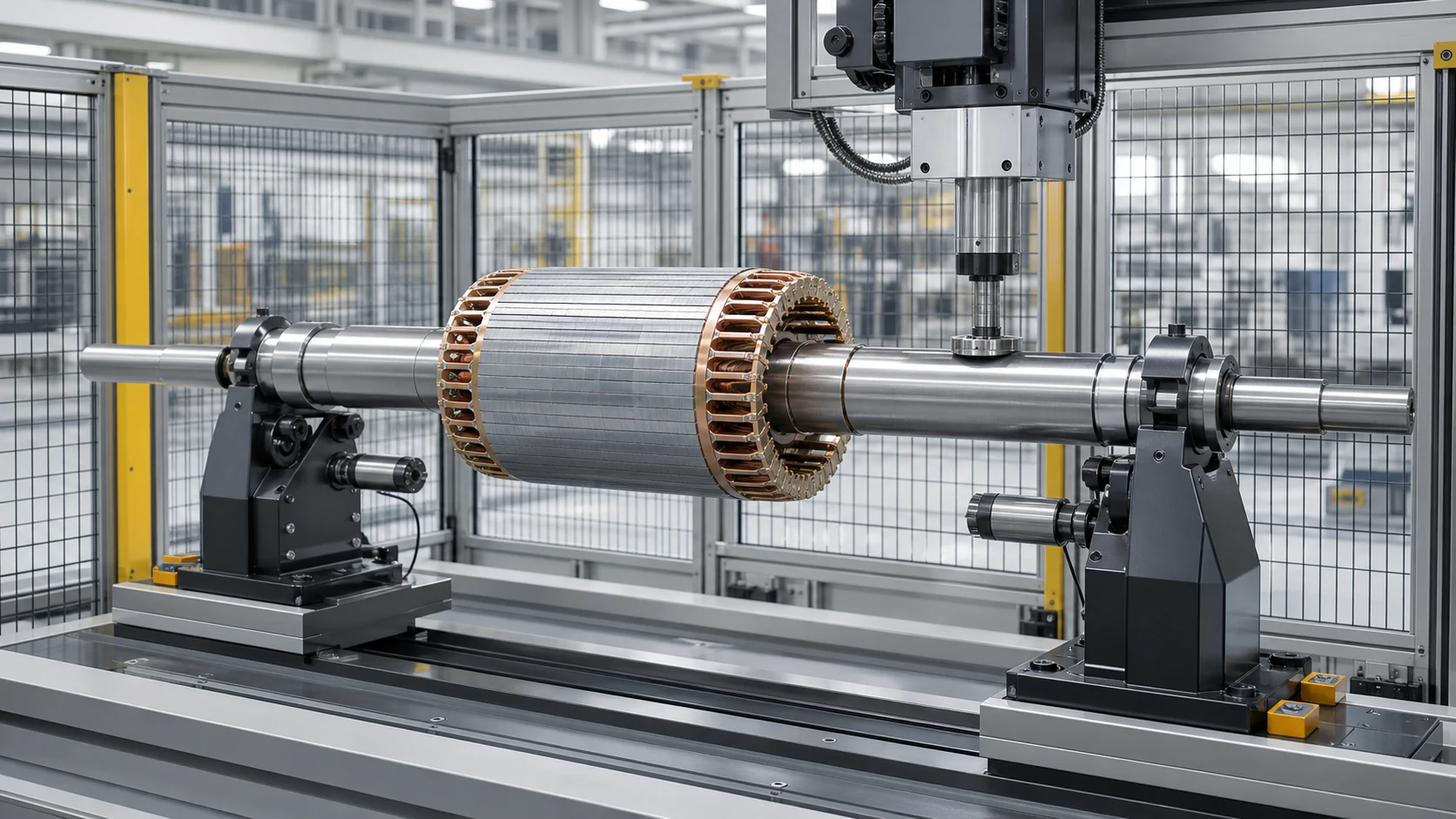
*Insenerikontseptsiooni illustratsioon. The geometries are generic screening examples, not verified StraighteningTech customer parts or current machine coverage.*
3. Measure the Incoming Deviation
Kontaktandmed, non-contact sensors or functional gauges record deviation at approved positions. The system should distinguish a true bend from contamination, a groove, a diameter transition or unstable seating.
4. Calculate the Correction Position and Direction
The controller identifies the dominant axial and angular bend position. For shafts with several bends, the sequence must avoid correcting one location while creating an unacceptable result at another.
5. Rakendage kontrollitud ülepainutamist
The press moves only to an approved zone and bends the shaft beyond the desired final position so that elastic springback leaves it closer to target. Stroke and, where appropriate, force limits are developed from sample response.
6. Remeasure and Decide
The same datum and measuring stations are used again. If the result remains outside target but stays within validated correction limits, another controlled correction may be allowed. Parts that reach a cycle, insult, force or plausibility limit are sent to NOK or engineering review.
7. Salvestamine ja mahalaadimine
If traceability is included in the confirmed control scope, a configured cell may store before/after values, retsept, correction count and OK/NOK result. The required data interface remains subject to project engineering and acceptance.
Protect Functional Features and Surfaces
A shaft can meet a runout value and still be unusable if the process marks a bearing journal, damages a thread, distorts a hollow wall or initiates a crack. Tooling and correction rules therefore need a feature-protection plan.
| Funktsioon | Typical Risk | Nõutav kontroll |
|---|---|---|
| Ground bearing or seal journal | Toetage või vajutage märke | Clean contoured contacts and approved contact pressure |
| Gear teeth or spline | Tooth damage or misleading probe signal | Functional measurement where required; no uncontrolled press contact |
| Keyway, soon või radiaalne auk | Stress concentration and crack initiation | Exclusion zone and conservative correction limits |
| Thread or worm section | Flank damage and unstable measurement | Measure on approved journals; protect threaded section |
| Äärik | Unstable support or face distortion | Dedicated locating and support concept |
| Hollow or thin-wall section | Ovaalsus, denting or collapse | Distributed support and tube-specific tooling |
| Karastatud üleminek | Brittle response or crack risk | Hardness/batch review, sample trials and stop limits |
| Coated or finished surface | Cosmetic or functional damage | Compatible contact materials and cleanliness control |
One Platform May Cover Multiple Shaft Models
A flexible cell may cover a shaft family when machine travel, force and sensor range overlap and change tooling can reproduce the correct datum. Model coverage must be proven across the complete envelope, not only on a nominal sample.
*Insenerikontseptsiooni illustratsioon. It shows a possible released-state verification arrangement without claiming a datum, uncertainty, tolerance or accepted result.*
| Cell Module | Questions to Resolve |
|---|---|
| Base machine and press | Required travel, force/resolution window and correction access |
| Toed ja pöörlemine | Datum, ulatus, surface protection and model change method |
| Mõõtesüsteem | Anduri tüüp, number of stations, probe force and gauge correlation |
| Käitlemine | Käsiraamat, salve, konveier, portaal või robot; orientation and buffer size |
| Juhtnupud | Recipe management, correction model, stop limits and abnormal-part logic |
| Quality data | Before/after values, jälgitavus, export and customer interface |
| Ohutus | Valvamine, blokeeringud, overload protection and maintenance access |
Shaft Application Paths
This hub organizes shaft inquiries by workpiece because each family has different datum and feature-protection rules. Reviewed published examples currently include motor shafts, automotive axle shafts and small motor worm shafts. Other families—including textile shafts, lead or ball screws, veovõllid, rootorid, rullvõllid, väntvõllid, camshafts and piston rods—remain evaluation routes whose project fit must be established from direct evidence and representative samples. Railway axles, machine-tool spindles and plasticizing screws are not represented here as current verified StraighteningTech capabilities. Solid shaft, hollow tube and long bar identities must be confirmed before assigning a cylindrical workpiece to a solution family.
For reviewed published examples, vaata Automaatne mootorivõlli sirgendamise lahendus, Autode teljevõlli sirgendamise lahendus ja Väikese mootori tiguvõlli sirgendamise lahendus. Each new project still requires its own drawing and sample review.
Sample Validation Before a Final Proposal
Representative trials convert a machine concept into a defendable project specification. The sample set should include short/long, small/large diameter, normal/worst incoming bend, and relevant material or heat-treatment batches.
| Valideerimisüksus | Tõendid registreerimiseks |
|---|---|
| Measurement agreement | Datum, sondi positsioonid, gauge method and correlation result |
| Sissetulev seisund | Painde jaotus, surface state and abnormal samples |
| Parandusvastus | Stroke/force response, springback and correction count |
| Final result | All required measuring stations, not only the worst initial point |
| Part integrity | Kontakti märgid, praod, thread/tooth/flange condition and other risks |
| Production fit | Laadimine, üleminek, cycle distribution, NOK handling and data needs |
| Vastuvõtmise piir | Tested part family and conditions covered by the final quotation |
No universal accuracy or cycle-time claim applies to every shaft. A final guarantee should state the workpiece family, protsessi etapp, sissetulev vahemik, datum, mõõtmismeetod, sample evidence and acceptance conditions.
Information Needed for a Shaft Straightening Proposal
Palun esitage:
- 2D joonistamine ja, if available, 3D mudel;
- shaft material, kõvadus ja kuumtöötlemise seisund;
- minimum/maximum diameter, length and model matrix;
- keskused, laagripäevikud, rootori istmed, hammasrattad, splainid, äärikud, threads and other functional features;
- sissetuleva kurvi või väljajooksu jaotus, sealhulgas halvimatel juhtudel;
- required characteristic, sallivus, datum and customer inspection method;
- lubatud toetus, measuring and pressing zones;
- sensitive surfaces and prohibited contact areas;
- current process stage and next manufacturing or assembly step;
- tootmismaht, sihttakti tund, loading direction and changeover needs;
- representative samples covering the full family.
KKK
Can one shaft straightening machine handle every shaft type?
Ei. A platform can cover a validated family when its travel, jõudu, andurid, supports and tooling match the complete envelope. A geared, flanged, hollow or highly slender shaft may need a different measuring or correction concept.
Is straightness the same as TIR?
Ei. Straightness is a datum-independent form control. A TIR reading is a shop-floor max–min indication whose datum, probe station or path, rotation and reading rule must be documented; it is not automatically GD&T total runout. The drawing and customer gauge method must determine what the machine measures and accepts.
Should a stepped shaft use a roller straightener?
Roller straightening is a common starting candidate for constant-section material. After functional features are finished, a stepped shaft may instead require datum-based measurement, protected contact zones and local point correction; the drawing and sample trials decide the route.
Can hardened shafts be straightened without cracks?
It may be feasible, aga kõvadus, geomeetria, stress concentrations and incoming bend change the risk. Conservative correction limits, representative trials and crack or surface inspection requirements must be agreed.
Does shaft straightening replace balancing?
Ei. Straightening controls geometry or runout; balancing controls mass distribution during rotation. A drive shaft or rotor may require both processes, with a defined sequence and separate acceptance criteria.
Kuidas on kiireim viis kasuliku ettepaneku saamiseks?
Saatke joonis, materjal/kõvadus, incoming and target measurements, datum, kaitsealad, production requirement and representative samples. This allows the engineering team to recommend a process and machine concept instead of guessing from diameter and length.
Build the Solution from the Workpiece
The reliable route is workpiece classification, measurement definition, meetodi valik, protected-zone design and sample validation. This prevents a machine from being selected around an incomplete tolerance statement or a convenient but non-functional datum.
Võtke ühendust StraighteningTechiga with your shaft drawing and sample information. Our solution team can prepare a proposed measuring, parandus, handling and validation concept for engineering review; final scope remains subject to drawing and sample validation.
Tehnilise viite piir
This hub uses public technical material from ISO/ASME dimensional specification frameworks and established straightening-machine manufacturers to describe industry terminology, workpiece families and possible process architectures. Those sources do not prove StraighteningTech machine range, andurid, control algorithms, täpsust, tsükli aeg, traceability functions or delivery history. Project-specific claims require StraighteningTech drawings, configuration records, representative trials and released acceptance evidence.