
A fuel injector needle is one of the most demanding straightening workpieces in mass production. The needle valve couple of a diesel or gasoline direct-injection injector is a lapped pairing with a radial clearance measured in a few micrometers, a long slender needle with a seating cone at one end and a shank that carries the control collar, spring seat and guide lands. A bend of a few micrometers over the needle length is enough to bind the couple, delay needle lift, distort the spray or cause dribble at the seat. Straightening at this scale is not a coarse press operation; it is a micro-correction process built on a measurement system that must be an order of magnitude finer than the tolerance it controls.
An injector needle straightening solution therefore starts from the functional drawing of the needle family, not from a machine catalog. It must answer which lands define the guide axis, how a bend of a few micrometers will be measured repeatably on a part only a few millimeters in diameter, where a correction force may be applied without touching lapped surfaces, and how the corrected needle will be verified in terms the injector assembly line actually uses.

See on insenerikontseptsiooni illustratsioon, mitte kliendi saidi foto. Probe types, support tooling and correction capacity for injector needles require drawing review, cleanliness planning and correlation tests on representative samples.
Why Injector Needles Need a Dedicated Straightening Solution
Needles sit at an awkward intersection: they are shaft-like in geometry, but their tolerances, materials and surface finishes belong to the precision-coupling world. Several features drive a dedicated solution.
| Needle Feature | Sirgendamise risk | Projekti vastus |
|---|---|---|
| Lapped guide lands with micrometer clearance | Any contact mark or local yield changes the couple’s fit | Correction only in zones the drawing defines as non-functional |
| Seating cone at the tip | The cone is the reference feature and the most fragile one | No contact tooling on the cone; measure it, never press on it |
| High-hardness carburized or through-hardened steel | Hard material needs precise, väikesed löögid; brittleness punishes overshoot | Micro-stroke press with springback compensation per part |
| Slender proportions | Self-weight and clamping deflection are the same order as the tolerance | Horizontal measurement on defined supports, minimal clamping force |
| Pairing with a lapped body | Geometric straightness alone does not guarantee couple function | Correlate machine readings with the customer’s couple test |
| Cleanliness requirements | Straightening debris or fingerprints contaminate the injector | Clean cell practice, no grinding or abrasive steps in the loop |
Define Which Needle Is in Scope
Injector needles vary more between programs than their appearance suggests. The straightening concept should be written against an exact part family.
| Needle Family | Tüüpiline ehitus | Peamine sirgendamise küsimus |
|---|---|---|
| Diesel common-rail needle | Long slender needle, seating cone, control collar or hydraulically balanced geometry | Shank bend relative to guide lands; cone-axis relationship |
| GDI high-pressure needle | Similar proportions, often with a control valve element | Bend plus control-feature geometry after heat treatment |
| Piezo or servo-control needles | Additional coupled components in the train | Project-specific review; correction may sit elsewhere in the train |
| Service or reclaimed needles | Worn, possibly scored or corroded parts from the field | Not a straightening candidate; inspection and sorting only |
This page concerns bare needles in controlled production, upstream of lapping or between rough and finish operations. It does not treat the lapped nozzle body, and it does not recommend correction of needles that have already seen service, because service damage modes such as scoring, cavitation erosion or seat hammering are not bend problems and cannot be pressed out.
Deformation Modes and Where They Come From
Needle distortion is created almost entirely by heat treatment, grinding and handling. The useful failure-model split is:
- Simple bow from stress release during carburizing, hardening or tempering. The dominant mode and the only one a straightening press should be asked to correct.
- Local kink near the tip from handling contact, dropped trays or jammed vibratory feeding. A sharp, short-radius defect on a hardened part is a rejection, not a correction candidate, because the local plastic work has already consumed the material’s ductility.
- Grinding-induced form error where the wheel removes stock unevenly on an already bowed blank, leaving a part that is dimensionally in tolerance but geometrically curved. The straightening step and the grinding allowance must be coordinated so finish lands stay on the correction map.
- Twist or bending of the cone axis relative to the shank, which can appear as a cone-axis-to-shank concentricity error. Whether this is correctable depends on the drawing definition and must be settled part-family by part-family.
As with every family in this field, the first project step is a deformation census: measure a statistically meaningful batch, classify the shapes, and only then decide how many correction points the machine needs. On needles the census usually shows that the vast majority of parts carry a single-plane bow, which simplifies the machine concept considerably, but this must be demonstrated rather than assumed.
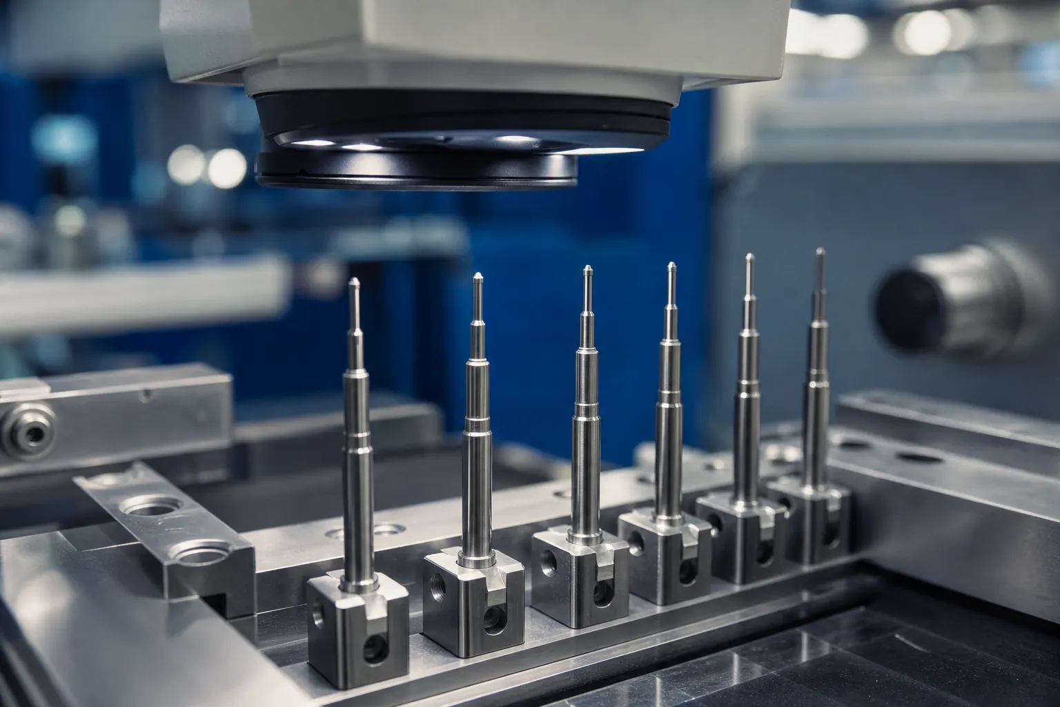
Measurement Datum and the Instrumentation Problem
The reference axis of an injector needle is the axis of its guide lands, the same lands that define the fit in the nozzle body. The measured characteristic is normally the bend of the shank relative to that axis, together with the cone-axis relationship where the drawing controls it. Two families of measurement are practical in production, and the choice drives the whole cell:
Rotation on precision centers or vee supports with contact probes. The classic approach, using low-force LVDT probes at several stations. Its limits on needles are center-hole quality, probe force deflecting the part, and stylus wear on hard surfaces. It works when the measuring plane budget is generous, and the general methodology is described in our article on LVDT multipoint shaft measurement.
Noncontact optical or pneumatic measurement of the free part. The needle rests on clean supports and is measured by optical micrometers, capacitive or air-gauge sensors without probe force. This removes the deflection artifact, protects lapped surfaces and suits the single-plane bow that dominates the family. The trade-offs between methods are laid out in contact versus noncontact straightness measurement; at needle scale the noncontact route is usually the only one that meets a repeatability budget an order of magnitude below the tolerance.
Whatever the sensor choice, gauge repeatability must be demonstrated on real needles before any correction loop is tuned. A gauge that cannot repeat to a fraction of the bend tolerance will train the press to chase noise, which on hard slender parts means scrap.
Correction Process: Micro-Strokes on a Protected Part
The correction machine for needles is a precision press in the low-force range, and its behavior matters more than its capacity. Four rules govern the process:
Correct only in permitted zones. The drawing review identifies zones where local plastic deformation is acceptable, typically mid-shank regions away from guide lands, the collar and the cone. Supports and the ram pad contact only those zones, through soft polished pads in a clean environment.
Work in micro-strokes with per-part springback compensation. Hard slender needles spring back almost entirely under small loads, then yield abruptly. The control system measures, computes the bend plane and magnitude, applies a small stroke, releases, remeasures and iterates. The stroke target is the predicted relaxed position, not the geometrically straight position, exactly as in conventional shaft work but with far smaller increments.
Respect the Bauschinger effect. Each reversal of stress lowers the local yield stress in the opposite direction, so repeated over-and-back correction cycles change the material’s response and can leave the part dimensionally straight but metallurgically unstable. The number of correction cycles per part should be limited and recorded; our article on the Bauschinger effect in straightening covers the mechanism in depth.
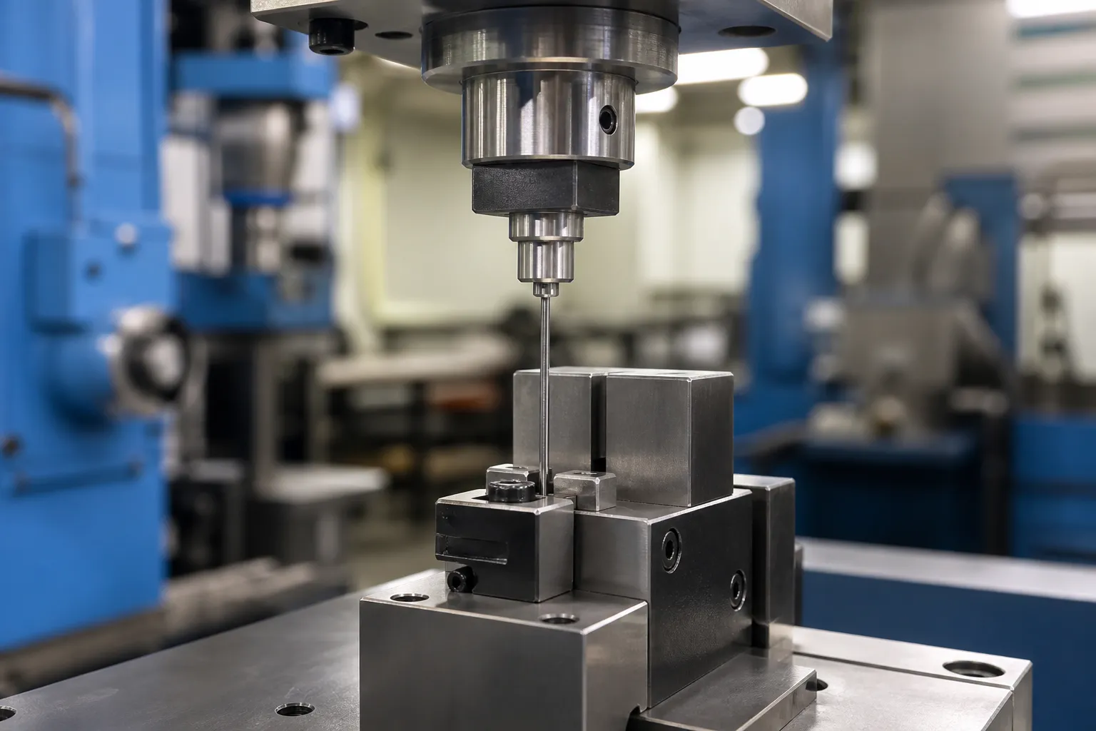
Puhas, mark-free handling throughout. The cell must not introduce the defects it exists to remove. Soft tooling, filtered air, no abrasives and a documented cleaning path to the downstream lapping or assembly stage are part of the machine specification, mitte järelmõte.
Acceptance Criteria and Correlation with Couple Function
Acceptance for needles is written on two levels, and a project should define both:
- Geometric acceptance on the machine: bend magnitude at defined stations relative to the guide-land axis, plus the cone-axis relationship where specified, with a measuring condition (toetab, anduri tüüp, planes, repetitions) written into the protocol.
- Functional correlation: a demonstrated statistical relationship between machine-accepted needles and downstream couple results, slide test or lift behavior in the injector. Without this correlation, a straightness limit is an arbitrary number.
The acceptance run should also fix the rework limit: how many cycles a part may see, at what bend magnitude the part is sorted out instead of corrected, and how NOK parts are segregated. On precision couplings, an honest reject stream is cheaper than an aggressive correction loop that saves parts geometrically and loses them functionally.
Automation and Volume Considerations
Injector needle production runs at volumes where manual correction is neither repeatable nor traceable. An automated cell loads needles from clean trays or vibratory-equivalent gentle feeding, identifies each part, measures it, decides whether it is a correction candidate or a reject, applies the micro-stroke sequence within the cycle limit, remeasures and sorts into acceptance classes. Because the parts are small and light, takt time is rarely the constraint; gauge repeatability, cleanliness and data integrity are. The cell should record every part’s as-measured curve, the strokes applied and the final result, so that when downstream couple tests drift, engineering can reconstruct whether the straightening process contributed or whether the cause lies in lapping, body geometry or contamination.
Common Pitfalls in Needle Straightening Projects
| Pitfall | Tagajärg | Prevention |
|---|---|---|
| Contact probing on lapped lands | Marking changes the couple fit the process exists to protect | Noncontact measurement or very low-force probes outside functional zones |
| Pressing near or on the cone | Seat damage that no straightness gain can justify | Protected-zone map with the cone excluded absolutely |
| Correcting local kinks on hardened tips | Fracture or delayed cracking in service | Sort kinked parts; correct only simple-bow parts |
| Gauge repeatability not demonstrated | Press chases measurement noise and overshoots | Gage R&R on real needles before loop tuning |
| Unlimited correction cycles | Bauschinger-driven instability, parts drift after acceptance | Cycle limit per part with traceability |
| Straightness treated as equivalent to couple function | Parts pass geometry and fail the injector test | Correlate machine limits with downstream couple acceptance |
Kokkuvõte: What a Needle Straightening Project Must Specify
A workable request for quotation for injector needle straightening contains the needle drawings with guide-land and cone definitions, the heat-treatment route, a deformation census with distributions, the acceptance gauge and couple-test definition, and the cleanliness requirements of the downstream process. From that package the machine concept follows: noncontact or micro-force measurement stations, a low-force precision press with per-part springback compensation, protected-zone tooling, cycle limits and a sorting strategy, and a data interface that lets quality engineering see what the process is doing to every part.
The needles that matter most are the ones the process never has to press: reducing distortion in heat treatment and handling is always the first lever. The straightening cell is the controlled, measured answer for the distortion that remains, and on parts with micrometer clearances it succeeds only when measurement, correction and acceptance are designed as one system.