
Long profiles, rails and non-round sections can show different geometry depending on where and how they are supported. A full-length scan can provide richer evidence than a few local checks, but a dense point cloud or trace does not automatically create a valid straightness result. The datum, scan path, feature selection, filtering, support condition and acceptance calculation must be defined first—otherwise the scan is a picture, not a measurement.
This is an inspection-planning framework. It does not claim that StraighteningTech provides scanning hardware, non-contact measurement, a specific scan length, accuracy or software capability; it defines what a scan-based straightness result must specify to be usable as acceptance evidence, and what it must not silently assume.
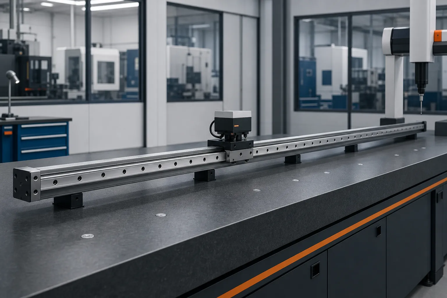
*Engineering concept illustration. It is not a scanned customer part, equipment specification or verified measurement output.*
Choose the Controlled Feature and Reference
“Full length” is not a measurement definition. Identify the actual feature: a functional face, centerline, edge, rail reference, web, flange or another drawing-defined element. Decide where the part is supported, how its orientation is held, and whether the result represents a free, supported or clamped condition. Two scans of the same rail on different supports are two different measurements of two different conditions—and both can be internally perfect while disagreeing completely.
| Planning item | Why it must be controlled |
|---|---|
| Drawing feature and datum | Prevents measuring a convenient surface instead of the required one |
| Support positions | Can change long-part deflection and apparent geometry |
| Scan path and spacing | Determines whether local transitions and long-wave bow are visible |
| Start/end treatment | Avoids unreviewed edge, chamfer or fixture artifacts |
| Feature segmentation | Keeps holes, joints, steps and excluded regions traceable |
| Calculation/filtering | Prevents a display setting from becoming an unstated acceptance rule |
For a related workpiece context, see linear guide rail straightening. That application page does not establish a scanning capability.
Support Strategy Decides What You Will See
On long slender sections, the support layout is not a setup detail—it is part of the measurement definition. A part sagging under its own weight between distant supports shows gravity deflection layered on the true geometry; closer supports suppress the long-wave component but can introduce local flattening at the contact points. Classical metrology handles this with defined support positions chosen to minimize or standardize self-weight effects, and the same thinking applies on any scanning bench: the support positions, their width and the part orientation are parameters of the result, and they must be recorded with it.
Three practical consequences follow. First, comparisons across time are only valid at constant support and orientation—changing the support layout mid-trend silently changes the measured quantity. Second, the machine-measured and the customer-measured condition must either share the support definition or have their difference handled as a defined correlation problem, which is the machine gauge versus customer gauge correlation case. Third, where the drawing defines the characteristic on the free part, supported scans need a documented rationale before their numbers are treated as the characteristic value.
Sampling Density and What It Can and Cannot Resolve
A scan can only see geometry at wavelengths its sampling can represent. Spacing between measured points sets a physical limit on the shortest deviation the result can carry: features narrower than the sampling interval average out, and local spikes—shoulder edges, damage marks, weld transitions—can alias into misleading long-wave shapes. Two rules follow for planning:
- Density serves the drawing characteristic, not the marketing one. A long-wave bow tolerance over the full length does not need the point density that a local flatness or edge-straightness callout does. Specify density from the smallest feature the acceptance must resolve, and record it as part of the method.
- Density is not accuracy. A fine point spacing on a trace whose datum, filtering and sensor behavior are undefined is a high-resolution picture of an undefined quantity. Sensor specification, datum extraction and calculation rules carry the metrological weight; spacing only decides what is visible.
Preserve Raw Data and the Calculation Path
A scan result should be reproducible. Retain part identity, drawing revision, measurement setup, support state, instrument status, operator or system identity, raw or traceable source data, processing version, excluded regions and the final reported value. If data smoothing, alignment or best-fit logic is used, document it and ensure it matches the approved method—because the same raw trace processed under two different reference rules yields two different straightness numbers, and only the documented path tells you which one the drawing means.
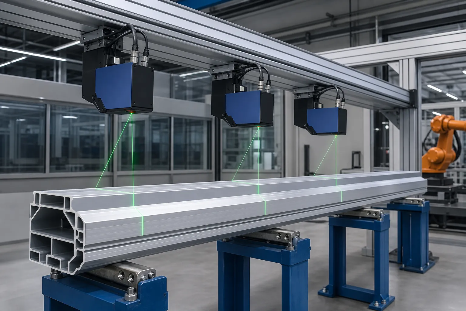
*Engineering concept illustration. Feature selection, scan resolution and data processing must be reviewed for the actual part and requirement.*
Do not compare results from different support positions or processing rules as though they were one continuous trend. When the method changes, re-establish correlation and update the controlled work instruction.
Separate Long-Wave and Local Geometry
A profile can be globally bowed while also having local deviations near holes, welds, shoulders or handling points. The report should distinguish those patterns instead of compressing them into a single unqualified maximum. The corrective action may differ: one condition can relate to support, while another needs an approved local correction or process review.
The scan plan should identify regions excluded by drawing rule, known nonfunctional transitions, and areas that need their own characteristic. Never delete inconvenient regions merely to improve a reported value. Structurally, this means the report carries at least three result classes: the full-length characteristic as defined on the drawing, any defined sub-span or zone characteristics, and a notation of excluded regions with their justification. A single number that silently blends all three has already survived too many decisions to audit.
Correlate the Scan to Acceptance
If the customer uses a different gauge, span, datum or sampling rule, validate the relationship before accepting a scan as a substitute. Matched representative parts should be inspected with both methods under controlled conditions. Review bias, repeatability, support effects, data handling and the agreed allowable difference. The measurement-system structure for that study follows gage R&R discipline—the gage R&R for straightening lines guide and its measurement-uncertainty treatment in straightness inspection apply unchanged, because a denser sensor does not exempt a method from validation.
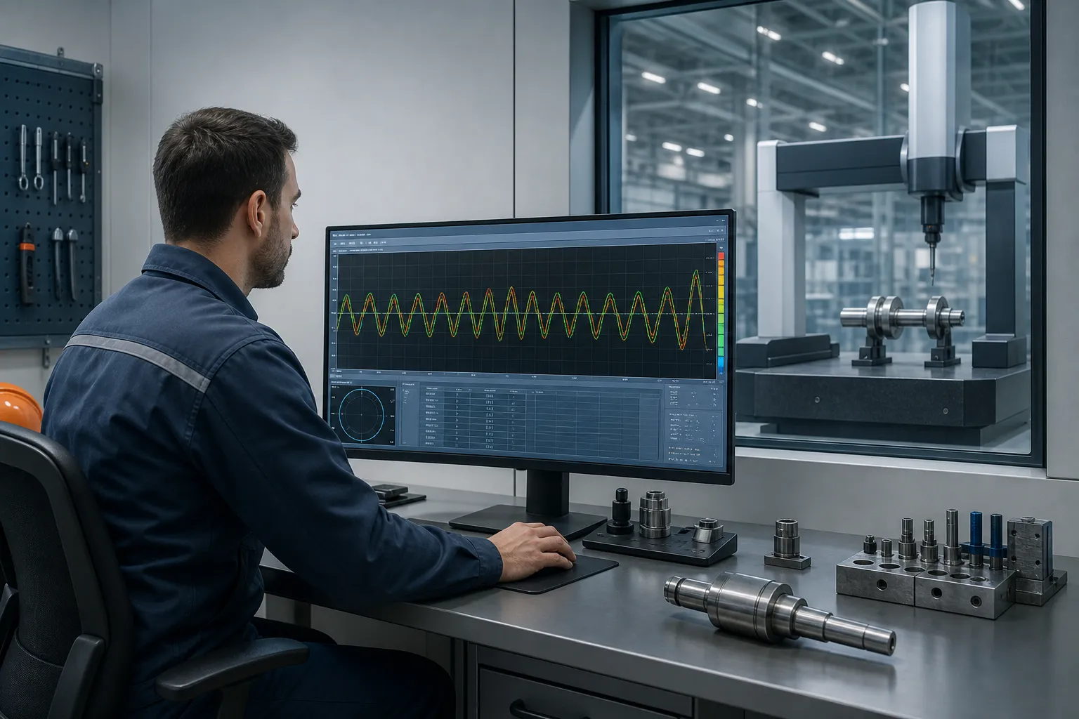
*Engineering concept illustration. It does not prove a scan method, machine configuration or acceptance result.*
Common Full-Length Scanning Mistakes
- Reporting “full length” without defining the feature. A trace of the most accessible surface is not the drawing characteristic. Feature and datum first, sensor second.
- Changing support between measurements. The most common broken trend: yesterday’s scan and today’s scan differ because the part sat differently, and the delta is read as process drift.
- Letting software defaults set the rule. Smoothing windows and best-fit settings chosen for display become de facto acceptance criteria when nobody writes down the real one.
- Treating resolution as accuracy. Thousands of points from an unvalidated sensing path do not add up to a traceable measurement.
- Excluding regions to pass. Every excluded region needs a drawing-based rule and a record; convenience is not a rule.
- Comparing scan to gauge without correlation. The scan is a substitute measurement only within the validated relationship—and the correlation framework defines how that authority is earned and limited.
What a Scan Report Must Contain
A scan that will support acceptance or process decisions needs a report structure that stands alone—readable months later, by someone who was not present. As a minimum field set:
| Report field | Content |
|---|---|
| Part identification | Part number, revision, serial or lot, traceability reference |
| Measurement definition | Controlled feature, datum, span, support positions and orientation |
| Method status | Instrument and sensor identity, calibration status, software and processing version |
| Data conditions | Sampling spacing, environmental conditions, operator or system identity |
| Results by class | Full-length characteristic, zone or sub-span characteristics, excluded regions with justification |
| Disposition | Pass/fail against the defined rule, and who made the call |
From Scan Evidence to Process Decisions
The economic point of full-length evidence is not the number itself—it is the decisions the number can support. A stable, well-defined scan trend tells a straightening operation three things that local checks cannot: whether the long-wave error is drifting across lots, whether a correction applied at one location propagates along the length as expected, and whether a local deviation is stationary (part-specific damage) or recurring (process signature). Each of those routes maintenance and setup effort differently, and confusing them is how lines end up chasing part defects with process changes and process drift with part rework.
Feed the classified results into the same baseline discipline used elsewhere on this site: released-state comparison against an approved reference, drift recorded with context (lot, tooling, recipe), and any correlation to the customer’s gauge maintained under change control. A scan program that lands inside that structure becomes the long-part equivalent of the released-sample checks that govern wire and shaft lines—same evidence logic, higher spatial resolution.
Prepare a Full-Length Study
Provide the drawing and revision, required feature and datum, profile section, length, support restrictions, current inspection record, known error zones, acceptable data format, customer gauge method and representative samples. Use the straightening sample test and acceptance guide to define sample evidence, then contact StraighteningTech for application review.
Frequently Asked Questions
Does a full-length scan replace dial-indicator checks?
It replaces them only where the relationship between the scan result and the customer’s own method has been validated—including feature, support and calculation alignment. Without that, the scan and the indicator are two measurements of two different definitions, and the drawing decides which one carries acceptance authority.
How fine should scan spacing be?
Fine enough to resolve the smallest feature the acceptance rule cares about, and no finer than the sensing path’s validated behavior justifies. Density is a visibility decision driven by the drawing characteristic—it cannot compensate for an undefined datum or an uncorrelated calculation.
Why do two scans of the same rail disagree?
Check the four silent variables first: support positions, part orientation, datum or best-fit rule, and processing version. Differences in any of them produce systematic disagreement that has nothing to do with the part. Only after those are matched does the residual difference become a metrology question.
Should bow and local deviations be reported together?
Report them separately, under their defined characteristics, with excluded regions noted. A single blended maximum hides which condition is present and therefore which corrective path applies—support-related long-wave behavior and local damage are different engineering problems.
Can a scan be used for process control during production?
Yes, and that is often its best use—scan trends show long-wave drift and recurring local signatures that sampled dial checks miss. The control application still needs the same controlled definition (feature, support, processing) and a defined reaction rule per result class, so that trend signals route to setup, tooling or handling actions instead of to generic alarm.
Related StraighteningTech Resources
See how automatic shaft straightening works for the machine context, straightening sample test and acceptance for trial structure, and shaft straightness vs runout vs TIR for the characteristic definitions a scan report must align with.