階梯式醫療鑽矯正解決方案

A stepped medical drill component is not a uniform shaft. Its large and small cylindrical sections, 肩膀, transition radii, cutting end and drive end can each have a different functional role, stiffness and allowable contact condition. A straightening system must therefore measure and correct the workpiece by section instead of treating the entire length as one plain round bar.

The objective is not simply to make an indicator value smaller. The process must preserve functional features, avoid loading vulnerable transitions and produce a result that correlates with the customer’s drawing and inspection method.

Why Stepped Medical Drills Need a Dedicated Process

Medical drill families vary widely. Official product information from DePuy Synthes refers to stepped drill bits used with drill stops, while Stryker lists drill bits in different diameters and lengths. These references demonstrate workpiece diversity; they do not mean that every medical drill has the same material, geometry or acceptance requirement.

對於矯直項目, the following features change the process design:

工件特徵矯直後果
Multiple cylindrical diametersEach section may require a different measuring position, support span and correction limit
Shoulders and transition radiiLocal stress concentration makes these poor default press or support zones
Long reduced-diameter sectionLower bending stiffness increases gravity deflection and sensitivity to measuring force
Cutting or toothed endCutting geometry must be protected from jaws, probes and correction tools
駕駛, coupling or flat featureIt may be a functional datum but is not automatically a round runout surface
Heat-treated or surface-finished body回彈, marking and crack risk must be validated on representative samples
Stepped medical drill held in an automatic measurement and correction station

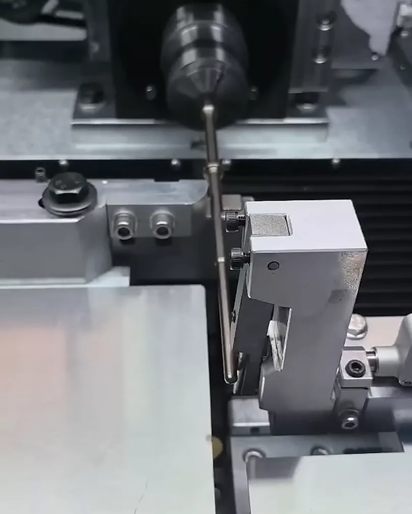
This real project frame shows a long stepped component held at a measurement and correction station. It confirms the workpiece and equipment arrangement, but it does not establish material, 方面, 精度或週期時間.

Define the Drawing Requirement Before Selecting the Machine

The word “straightness” is often used for several different characteristics. 國際標準化組織 1101 提供幾何公差語言, but the drawing still has to identify the actual characteristic and datum system.

Before a quotation or sample trial, confirm whether the customer needs:

  • axis straightness of one cylindrical section;
  • radial runout or total indicated runout relative to selected journals;
  • coaxiality or position between two stepped sections;
  • a full-length envelope requirement;
  • local straightness per specified gauge length;
  • or a combined requirement covering geometry and surface condition.

These requirements are not interchangeable. A workpiece can show acceptable runout at one section while another reduced-diameter section remains outside its drawing tolerance. It is also possible to improve one indicator trace while worsening coaxiality between sections if the datum strategy is wrong.

Reported Project Inputs Are Not Final Specifications

The source application described a workpiece approximately 230 mm long with reported diameters near 7.9, 6.9 和 5.9 毫米. It also mentioned a 0.05 毫米目標. These values are useful for planning a sample discussion, but they are not treated here as verified production results.

Before engineering approval, the customer must clarify:

所需輸入為什麼這很重要
Controlled drawing and revisionPrevents tooling and inspection from being built around obsolete geometry
Material and heat-treatment conditionDetermines stiffness, 回彈, crack risk and allowable contact pressure
製造階段Defines whether cutting features, 塗層, passivation or final finish already exist
Datum and characteristicDetermines support, rotation and probe locations
Initial bend distributionDetermines required correction travel and whether the part is recoverable
Prohibited contact zonesProtects shoulders, cutting features, finishes and functional coupling surfaces
Customer gauge or correlation samplesMakes machine results comparable with final acceptance inspection

Section-Specific Measurement Strategy

The measuring system should not assume that one pair of centers or one cylindrical surface represents the full workpiece.

1. 建立功能基準

Select datum surfaces from the drawing and end-use assembly logic. Suitable candidates may include finished journals, a defined shank diameter or a controlled center feature. A shoulder, 長笛, relief or untreated blank surface should not become the datum merely because it is easy to contact.

2. Control Support and Gravity Effects

Long reduced sections deflect under their own weight. Horizontal support does not eliminate gravity error. The sample method must define support locations, free span, workpiece orientation, rotation speed and probe force. The machine and customer gauge should inspect the same characteristic under correlated conditions.

3. Measure More Than One Section

Use drawing-defined axial stations on the relevant diameters. A probe must remain on an approved cylindrical land and must not cross a shoulder or relief during measurement. If the part contains a non-round feature, the system may need angular indexing or a different sensor rather than a conventional contact indicator.

Long stepped medical drill positioned against a low-force measurement station

The video frame shows the workpiece near a compact sensing/correction assembly. The exact sensor type and force are project-specific and must be confirmed during machine design.

Protected Correction-Zone Design

Point correction should act only on approved steel zones. It should not be placed automatically at the largest measured deviation if that location is a shoulder, transition radius, cutting feature or other restricted area.

Create a correction map before programming:

Zone type預設規則
Stable cylindrical body sectionCandidate support or correction zone after surface-pressure review
Reduced-diameter long sectionUse lower force increments and tighter travel limits
Shoulder and transition radiusProhibited or specially engineered contact zone
切割, toothed or fluted endProtect from direct pressing and hard clamping
Drive/coupling featureLocate only with variant-specific tooling
Finished or coated surfaceUse validated contact material and marking criteria

The control sequence should apply a limited correction, release the load, remeasure and update the next action. This measure–correct–remeasure loop is essential because springback can vary between diameter sections and heat-treatment batches.

Controlled correction station for a long stepped medical drill component

Example Automatic Process

An automatic stepped medical drill straightening cell can be configured around the following sequence:

  1. Load or receive the workpiece without striking the cutting and shoulder features.
  2. Confirm part presence and, 如有需要, variant identity.
  3. Locate the approved datum surfaces and control axial position.
  4. Rotate the workpiece and measure the specified sections with controlled support and measuring force.
  5. Calculate the bend direction and identify an approved correction location.
  6. Apply a limited point correction with force or displacement monitoring.
  7. 發布, rotate and remeasure the relevant sections.
  8. Repeat only within validated iteration, force and travel limits.
  9. Classify the part as accepted, rejected or requiring engineering review.
  10. Record the final result and relevant process data when traceability is required.

The actual cell may use manual loading, a magazine, a robot or another transfer method. Automation level should follow the part family, 批量大小, orientation stability and cleanliness requirements rather than being assumed from one demonstration video.

Real Stepped Medical Drill Straightening Video

The following video from the Straightening Machine channel shows a long medical drill component at an automatic measurement and correction station.

The video demonstrates equipment motion and the physical workpiece. It is not an inspection report and does not prove a universal tolerance, production rate, 產量或客戶接受度.

Sample Validation and Acceptance

A representative sample trial is the correct basis for confirming feasibility. It should include the worst credible combinations of diameter, 長度, 物質條件, initial bend and surface state.

Recommended Sample Record

記錄Minimum content
零件標識Drawing number, 修訂, batch and manufacturing stage
傳入幾何圖形特徵, 基準, axial stations and measured values
流程設定支援職位, correction zones, force/travel limits and iteration count
最終幾何形狀Results from the machine and correlated customer gauge
表面狀況馬克, 凹痕, coating damage and cutting-feature inspection
物質條件Hardness or heat-treatment evidence when relevant
例外情況Rejected parts, limit violations and engineering dispositions

A reported target such as 0.05 mm cannot become a machine guarantee until the characteristic, 基準, 測量方法, initial condition and representative sample results are agreed.

Medical-Device Quality Boundary

國際標準化組織 13485 defines quality-management requirements for medical devices. In the United States, the FDA Quality Management System Regulation became effective on February 2, 2026 並納入ISO 13485:2016 by reference.

A straightening machine can support a customer’s controlled process through recipes, access levels, calibration planning, result records and change control. The machine itself does not certify the customer’s product, validate the complete manufacturing process or establish regulatory compliance. Those responsibilities remain with the legal manufacturer and its quality system.

This solution concerns manufacturing-stage components. It is not a proposal to repair or reprocess used surgical drills.

What We Need for a Stepped Medical Drill Proposal

Send the following information for engineering review:

  • drawing and revision;
  • 材料, heat treatment and surface condition;
  • manufacturing stage at which straightening is required;
  • diameter sections, overall length and shoulder geometry;
  • drawing-defined characteristic, datum and acceptance limit;
  • initial bend distribution and reject threshold;
  • 禁止接觸區;
  • customer inspection method and available correlation samples;
  • required production volume and loading preference;
  • 可追溯性, recipe and data-export requirements.

Our team will use these inputs to define a sample test, 測量概念, correction map and machine configuration.

常見問題解答

Can one program cover several stepped medical drill sizes?

可能, but each variant needs a controlled recipe and compatible locator, 支援, measuring station and correction-zone map. Similar overall length does not prove that tooling can be shared.

機器保證嗎 0.05 毫米?

Not from a target value alone. The characteristic, 基準, 測量, 初始彎曲, material state and sample results must be defined before a tolerance commitment is made.

Will straightening damage the shoulders or finished surface?

The solution is designed to avoid direct loading on restricted features and to control contact pressure. Final surface acceptance still requires representative sample inspection.

Is this the same process as straightening a uniform medical rod?

不. Multiple diameters change stiffness, datum transfer, probe locations and allowable correction zones. The process must be section-specific.

Discuss Your Workpiece

回顧我們的 Medical Drill application page醫療器械解決方案, 或者 聯絡我們的矯正解決方案團隊 with a drawing and sample information.

技術參考

目錄
捲動到頂部