電動工具加長桿矯正解決方案

A power tool extension bar may look like a simple slender shaft, but its two ends usually perform different functions. One end interfaces with a drill or impact driver; the other holds or drives a bit or accessory. Hexagonal sections, retaining grooves, sockets, holes and local heat treatment make the workpiece asymmetric and leave only limited zones that are suitable for measurement, support and press contact.

A reliable power tool extension bar straightening solution must therefore start from the drawing and the functional gauge. It must define the datum, separate shaft bend from end-interface error, protect critical surfaces and verify the result after every correction. It should not apply one tolerance, cycle time or automation concept to every 1/4-inch extension.

Identify the Workpiece Before Selecting a Machine

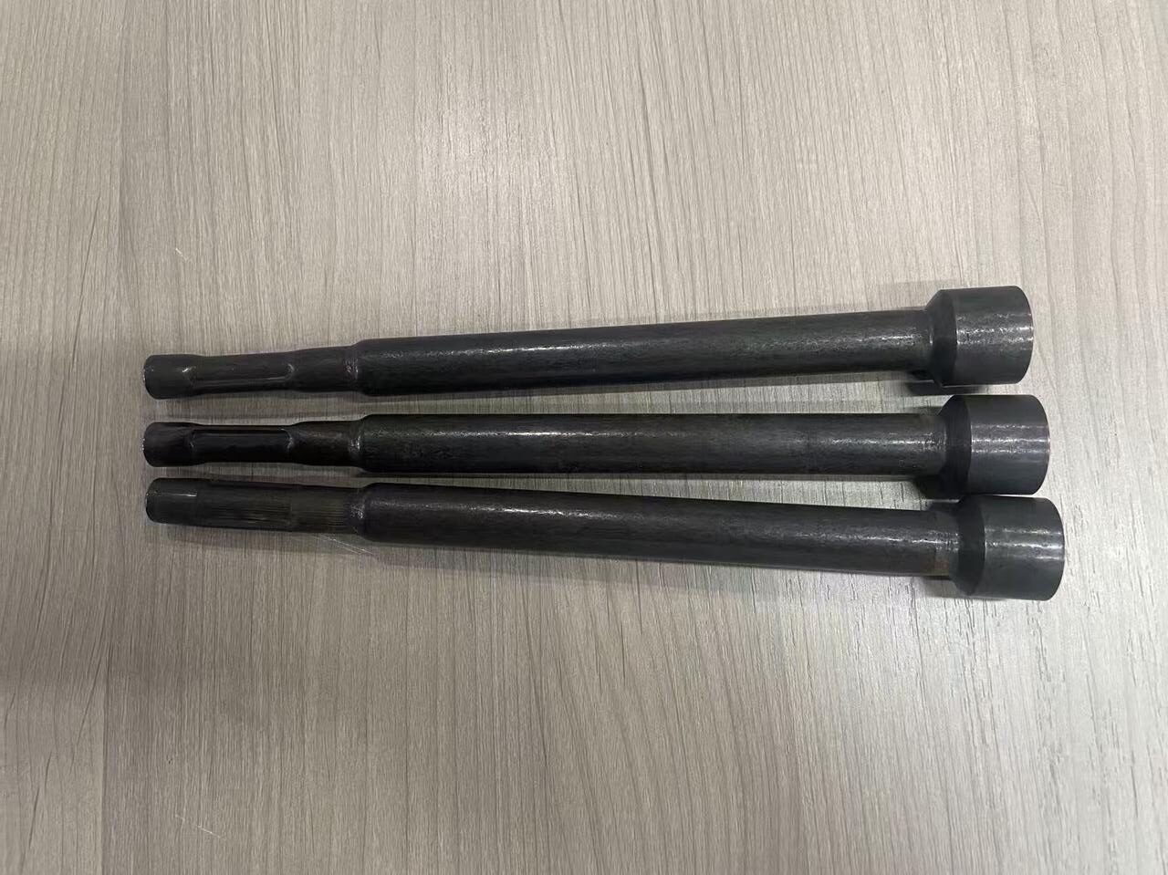
The real project photo shows several long power-tool extensions with different end geometries. They are not hollow sleeves and should not be confused with automotive engine connecting rods.

Power tool extension bars with different drive and holder end geometries

Official tool manufacturers use terms such as universal bit holder1/4-inch hex-shank extension for related product families. These names help define the application, but they do not prove that every extension has the same interface, material or acceptance method. The customer drawing remains the controlling source.

Before feasibility testing, identify:

FeatureWhy It Matters for Straightening
Input hex shankMay define the power-tool axis but is not automatically a suitable rotating measurement surface
Output holder or socketFunctional wobble can depend on its bore, retention feature and assembly condition
Smooth shaft zonesPotential measurement, support or correction locations if the drawing permits contact
Groove, cross-hole or transitionCreates a local stiffness change and may be excluded from pressing
Heat-treated zoneChanges springback and crack risk compared with the shaft core
Coating or finished surfaceLimits permissible probe, support and punch contact

Reported Project Inputs Are Not Universal Specifications

The earlier site article reported a 6.35 mm × 200 mm workpiece and a final target of 0.2 mm. These values are treated here only as reported project inputs. The available source does not define whether 0.2 mm means straightness, radial runout, total indicated runout, coaxiality or functional tip wobble. It also does not identify the datum, measuring positions or final gauge.

StraighteningTech will confirm the proposal from the actual drawing and representative samples. A commercial guarantee should only cover the tested workpiece family, incoming-condition window and agreed acceptance method.

直率, Runout and Functional Wobble

These characteristics are related but not interchangeable:

CharacteristicQuestion It AnswersRequired Definition
直率How far does a selected shaft line or surface deviate from an ideal straight line?Controlled zone, evaluation length and datum rule
Radial runout/TIRHow much does a surface vary while the part rotates about a defined axis?Rotation datum, probe position and filtering
同軸度How well do the input and output functional axes align?Both axes and the applicable drawing requirement
Functional wobbleHow much does an installed master bit or accessory move during rotation?Master tool, engagement depth, test speed and reading location

A part can have an acceptable smooth-shaft reading but still fail at the output holder if an end feature is eccentric or assembled incorrectly. Conversely, a varying hex envelope can produce an unstable probe signal even when the functional axis is acceptable. The machine measurement and the customer's final gauge must therefore be correlated during sample testing.

Information Required for a Straightening Proposal

Project InputRequired Detail
DrawingRevision, dimensions, datums and controlled characteristics
Product identityExtension bar, bit holder, adapter or another tool family
End interfacesHex standard, holder/socket geometry, bore, groove, hole and retention method
Material and heat treatmentCore hardness, locally hardened zones and coating
Manufacturing routeForming, 加工, 熱處理, grinding, plating and assembly sequence
Incoming deformationBend magnitude, direction and axial distribution from representative samples
Final acceptance直率, TIR, coaxiality or functional wobble with datum and gauge
Contact restrictionsSurfaces where supports, probes and the press punch may or may not touch
Production scopeVariant range, output target, loading method, changeover and traceability

Recommended Closed-Loop Straightening Process

1. Identify and orient the extension bar

The cell identifies the selected variant and confirms the orientation of the asymmetric ends. Feeding may be manual, tray-based, conveyor-based or developed around a validated bulk-feeding system. Random bulk loading is not assumed until the real part family has passed entanglement, overlap and orientation trials.

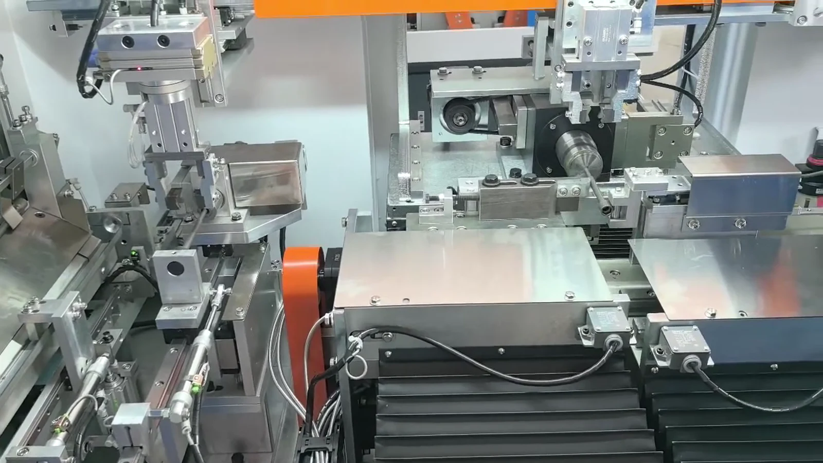
Automatic transfer and orientation station for power tool extension bars

The image above is a frame from the real project video. It supports the presence of automatic transfer/orientation hardware in the demonstrated station. It does not by itself prove random bulk loading or a 100% orientation rate.

2. Establish the functional datum

The workpiece is located by centers, approved journals, a controlled hex interface or dedicated fixtures according to the drawing. Supports must reproduce the inspection logic without forcing the slender shaft into a false straight condition.

3. Measure approved shaft zones

The extension rotates or indexes while sensors collect readings at defined axial positions. The measurement plan excludes grooves, cross-holes, socket edges and non-round zones unless a validated profile-specific method is used. The controller constructs an incoming bend curve and separates repeatable geometry signals from centerline displacement.

4. Select the support span and correction point

The controller selects an approved support span and press position. Tooling and software limits block contact with the drive corners, retention groove, socket lip, bore and other prohibited features.

5. Apply staged point correction

The press applies a controlled displacement or force at the selected location. Correction is incremental because thin shafts, heat-treated zones and abrupt section changes can have different springback. Maximum force, stroke and iteration limits prevent uncontrolled repeated pressing.

6. Remeasure using the same datum

After each press action, the system measures the workpiece again without changing the acceptance reference. Another correction is made only when the residual error is outside the approved process window.

Power tool extension bar positioned for measurement and press correction

7. Verify and discharge

The final machine reading is compared with the drawing-specific rule. Where functional wobble matters, the sample study also correlates the machine result with the customer's master tool or final gauge. Automatic separation, result storage and line communication are included only when specified in the ordered configuration.

Real Power Tool Extension Bar Straightening Video

The following public project video shows a real extension bar, transfer hardware and an automatic straightening station. It supports the workpiece application and visible process sequence; it does not prove a universal accuracy, 週期, yield or labor result.

Tooling and Surface-Protection Strategy

“No damage” is an acceptance requirement, not a generic promise. The actual tooling must match the allowed contact zones, hardness, coating and end geometry.

Tooling ElementDesign Question
End locatorDoes it reproduce the functional axis without marking or deforming the hex/holder interface?
SupportsDo they carry the correction load on approved smooth zones?
Press punchIs its radius/profile compatible with shaft diameter, hardness and permitted surface pressure?
Measuring probeDoes it read shaft displacement rather than hex corners, groove edges or socket geometry?
Changeover setIs each variant mechanically keyed and matched to the correct recipe?

For thin or hardened extensions, the feasibility test should establish a safe correction window. If the drawing or customer quality plan requires crack inspection, surface inspection or functional torque testing, those checks must be included in the validation and production plan.

Automation Is Selected After Feeding Trials

Automation LevelSuitable SituationTypical Scope
Manual loadingMany variants, lower volume or feasibility stageOperator loads; machine measures, corrects and verifies
Tray or magazine feedingStable orientation and controlled presentationGuided feeding, automatic cycle and result indication
Validated bulk feedingHigh volume and parts proven not to tangle or overlapFeeder, escapement, orientation checks and reject/recovery logic
Integrated lineStable family with upstream/downstream interfacesBuffer, 處理, result separation and agreed communication
Traceable cellPart-level records requiredPart ID, recipe, measurement and correction history

Cycle time must be measured on the final configuration. It depends on length, measuring positions, number of correction iterations, feeding method, variant checks and data requirements. A short video clip or one successful sample cannot establish production capacity.

Sample Test and Acceptance Plan

Representative samples

  • each end-interface and length variant included in the proposal;
  • normal parts plus samples near the expected incoming-bend limit;
  • each material, heat-treatment and coating condition;
  • parts from more than one production batch where springback may vary;
  • enough samples to evaluate repeatability, not only one corrected part.

Evidence to record

RecordAcceptance Evidence
Part identityDrawing revision, variant, batch and process route
Incoming measurementDatum, measuring positions, gauge and deformation curve
Tooling configurationLocators, support span, punch and prohibited contact zones
Correction historyPosition, force/displacement and iteration count
Final machine resultSame datum and method used for incoming measurement
Gauge correlationComparison with the customer's final or functional gauge
Surface/end inspectionMarks, cracks and interface condition to the agreed rule
Cycle observationMeasured time for the validated configuration

Common Failure Modes and Controls

Failure ModeLikely CauseControl
Unstable reading at a hex or grooveProbe follows profile geometryMove to approved smooth zone or validate profile-specific measurement
Shaft passes but holder wobblesWrong datum or eccentric end featureAdd interface-axis and functional-gauge correlation
Mark on hex, groove or socketIncorrect support/punch locationMechanically protect and software-block prohibited zones
Crack after correctionExcess bend, local hardening or unsuitable spanStage correction, set limits and add required crack inspection
Variant loads backwardsEnd geometry not reliably distinguishedAdd poka-yoke, presence/orientation sensing and reject logic
Result changes after changeoverTooling and recipe mismatchKey tooling and verify the selected variant before cycle start

What This Solution Does Not Promise Without Validation

  • one fixed accuracy for every 1/4-inch extension;
  • correction of every incoming bend or every heat-treatment condition;
  • zero surface marks, zero wobble or zero crack risk;
  • a universal 10–15 second cycle or a fixed yield percentage;
  • random bulk feeding or perfect orientation for every geometry;
  • one operator supervising a stated number of machines;
  • automatic traceability, MES connection or line integration unless ordered;
  • that a reported 0.2 mm target has already been achieved in stable production.

Related Straightening Equipment and Applications

For an adjacent machine configuration, review the ZD300 impact screwdriver straightening machine. For the wider workpiece family, see 工具矯正解決方案. These links provide equipment and application context; the correct configuration still depends on the actual drawing and sample test.

Information to Send for a Proposal

Send the drawing and revision, representative samples, end-interface details, material and heat treatment, manufacturing route, incoming deformation range, final characteristic and datum, measuring method, allowed contact zones, surface/crack requirements, output target, variant range and preferred loading method.

Contact StraighteningTech for a sample-based power tool extension bar straightening study. The proposal will define the measurement datum, tooling, correction limits, automation scope and acceptance evidence for your real workpiece family.

Frequently Asked Questions

Is every 6.35 mm extension measured in the same way?

不. A 6.35 mm or 1/4-inch interface identifies a nominal drive family, not the entire datum and inspection method. The end geometry, shaft zones, retention features and drawing requirement determine how the part is located and measured.

Can the machine measure directly on the hex shank?

Potentially, but a generic round-shaft probe will react to the hex profile. Measurement on an approved smooth zone is usually simpler. If the hex must define the functional axis, dedicated location or profile-aware measurement must be validated against the customer's gauge.

Can hardened extension bars be press straightened?

They may be feasible, but the correction window depends on material, hardness, hardened depth, incoming bend, support span and contact location. Representative sample testing and the required crack/surface inspection are necessary before a guarantee is made.

What accuracy can StraighteningTech guarantee?

Only the result demonstrated for the agreed workpiece family, incoming-condition window, datum and acceptance gauge can be guaranteed. A value from an earlier article, competitor page or video is not a substitute for sample evidence.

Does the machine include automatic feeding?

It can. Manual, tray, magazine, bulk and integrated-line handling are different project scopes. The final choice follows real-part feeding and orientation trials.

Terminology Reference Boundary

  • Wera universal bit holder: https://www.wera.de/en/tools/895-4-1-universal-bit-holder
  • Wera 893/1/1 universal bit holder: https://www.wera.de/en/tools/893-1-1-universal-bit-holder
  • Bosch Professional 1/4-inch hex-shank extension: https://www.bosch-professional.com/middle-east/en/extension-bars-for-spade-bits-1-4-inch-quick-change-2867392-ocs-ac/

These official references support terminology only. They do not imply that the pictured workpiece is made by those brands or that their product data define the StraighteningTech project.

目錄
捲動到頂部