
Захист поверхні при рихтуванні – інженерне рішення, не просто додати м’яку підкладку. Матеріал заготовки, розділ, закінчити, покриття, мастило, контактна геометрія, силовий шлях, Чистота інструментів і стан зношеності можуть впливати на сліди, сплющування, локальне пошкодження та сигнал геометрії, який використовується для керування процесом. Контактний спосіб, прийнятний для однієї планки, дріт або вал може бути неприйнятним для труби з покриттям, точний журнал, профільний куточок або готовий інструмент.
У цьому посібнику пояснюється структура перевірки. Він не стверджує, що StraighteningTech має певний рулонний матеріал, покриття, форма канавки, обмеження тиску або здатність поверхні заготовки. Ці предмети вимагають доказів фактичного інструменту та репрезентативних зразків.
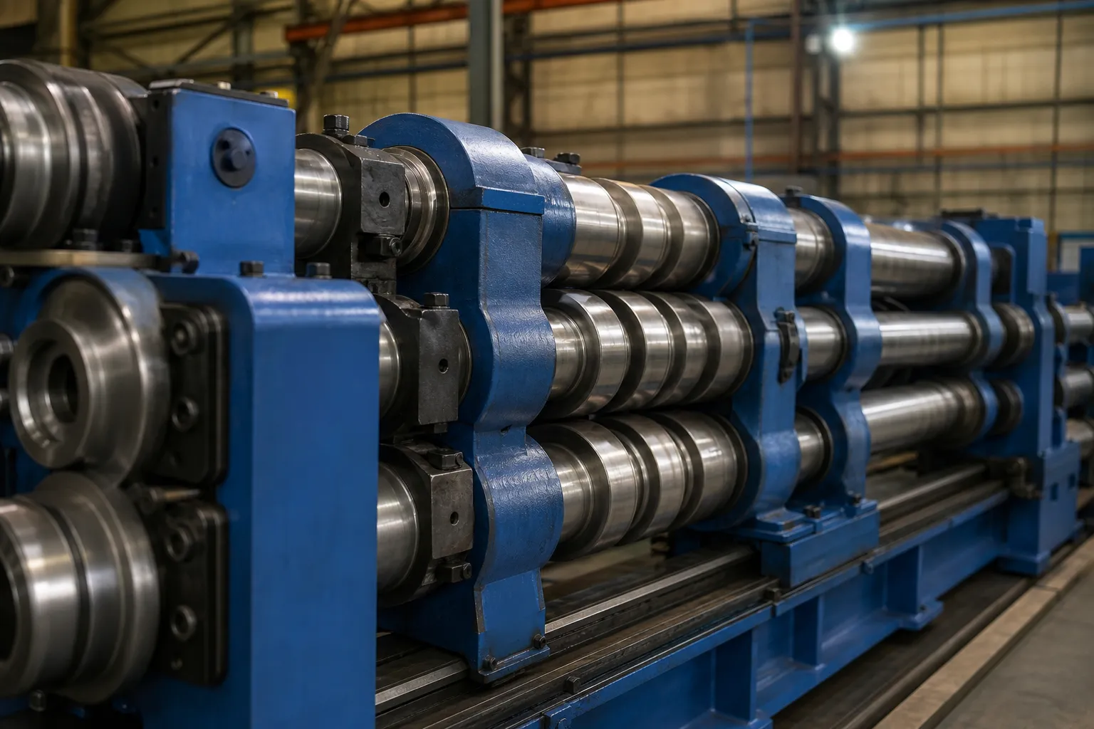
*Інженерна концепція ілюстрації. Він показує захист покриття як проблему перевірки конкретної заготовки, немає доказів схваленої універсальної канавки або контактного матеріалу.*
Перед судом, задокументувати особу інструменту, матеріал/оздоблення, де відомо, контактна геометрія, розташування установки, вирівнювання, спосіб очищення, стан змащення, де це можливо, стандарт перевірки та поріг заміни/зносу.
Where Marks Actually Come From
Surface damage in straightening has a short list of physical causes, and naming them is the first step to controlling them. Normal contact pressure between tooling and workpiece, multiplied by any relative sliding, produces the classic witness line. Debris trapped in the contact zone — scale, чіпси, grinding swarf — converts ordinary pressure into indentation and scratching, which is why cleanliness is a process variable rather than housekeeping. A contact geometry that concentrates load on an edge or a radius that is too small for the section raises local stress far above what the average force suggests. And beyond a threshold specific to each material and heat-treatment state, local plastic flattening of asperities or of the section itself changes surface geometry permanently. A bruised corner on a profile or a flattened zone on a thin wall is a geometry defect, not only a cosmetic one.
Every one of those causes has a countermeasure that lives in tooling design and process discipline: distribute force through larger or conforming contact areas, eliminate sliding by aligning the correction stroke with the support plane, exclude debris through scheduled cleaning and covers, and keep forces within the range the section can carry elastically. None of them is a pad. Soft inserts are one option among several, and they bring their own trade-offs — softer contact materials wear faster, deform under sustained correction cycles, and can change the effective support geometry as they age, which quietly alters the correction result.
Tooling Material and Contact Geometry Decisions
Selecting contact tooling is a three-way trade between surface protection, dimensional stability of the tooling itself, and wear life. Hardened steel tooling holds its groove geometry through long runs and keeps the measurement-and-correction loop repeatable, but it concentrates contact stress and tolerates no debris. Softer non-ferrous alloys and polymer inserts lower local stress and forgive small particles, at the cost of faster wear and periodic requalification of the contact form. Conformal contact — a groove or saddle matched to the section radius — spreads load compared with a flat anvil face, and generous radii on every edge that can touch the workpiece remove the stress concentrations that cause bruising even at moderate force.
Two disciplines make those choices verifiable instead of habitual. перше, each tooling element needs an identity: матеріал, contact form, the workpiece zones it is approved for, and a wear limit stated as a measurable criterion — profile deviation of the groove, visible embedding, dimensional change of the insert — not as a judgment call. друге, a change in any contact component is a process change: the first parts after a roll change, an insert renewal or a re-ground anvil run under the same sample-test evidence rules as a new setup, because the surface and geometry result must be reconfirmed, не передбачається. These are the same change-control habits that контрольні списки FAT машини enforce at acceptance, applied daily.
Підтримуйте інструменти в чистоті та контролюйте знос
Вбудоване сміття, зношені канавки, пошкоджені ролики, зміщення та непослідовне регулювання можуть призвести до появи позначок або неправильної геометрії. План захисту повинен визначати частоту перевірок, спосіб очищення, критерії зносу, контроль зміни інструменту та перевірка повторної кваліфікації після зміни контактного компонента. Не слід покладатися на візуальне твердження, що інструменти «виглядають добре».

*Інженерна концепція ілюстрації. Він описує захищений контакт як інженерну вимогу; він не встановлює місцевий роликовий матеріал, обмеження тиску або гарантія якості поверхні.*
Перевірте поверхню та геометрію разом
Захист поверхні не можна підтвердити лише перевіркою на наявність видимих подряпин. Випробування зразка також має підтвердити заплановану геометрію відповідно до схваленої бази даних і стану випуску. Маршрут, який захищає поверхню, але не відповідає необхідної геометрії, неприйнятний; маршрут, який відповідає геометрії, але пошкоджує функціональне покриття, неприпустимий.
| Елемент перевірки | Потрібні докази |
|---|---|
| Місце контакту та шлях реакції | Запис інструментів/налаштувань, пов’язаний із зонами малювання |
| Стан поверхні | Узгоджений метод перевірки до та після виправлення |
| Результат геометрії | Опубліковані показання на схваленому базі даних/калібру |
| Повторюваність інструменту | Повторити налаштування, перевірка чистоти та зносу |
| Контроль змін | Ідентифікація та повторна перевірка після зміни валків/канавок/інструменту |
використання випробування зразків випрямлення та прийняття визначити пакет доказів, і прес проти роликового випрямлення щоб визначити, чи слід оцінювати інший метод корекції.
The Force Path Matters More Than the Pad
The most common surface-protection failure is treating contact risk as a material question while ignoring load path. Where the supports sit, where the press point acts, and how those locations relate to the stiff features of the section determine how much force the operation needs in the first place. A correction stroke applied mid-span between widely spaced supports demands far more force — and leaves far deeper witness marks — than the same correction applied with supports closer to the correction point, even with identical tooling. Aligning the press axis with the support plane so the part does not slide or rotate under load removes the sliding component of damage entirely. On sections with asymmetric stiffness, pressing in the wrong direction loads a thin wall in bending and creates local dents that no insert material can prevent.
This is why surface protection is designed jointly with the correction plan, not bolted on afterward. The error map that drives the correction points should also mark the zones where contact is forbidden — finished journals, coating on sealing surfaces, polished flanks — and the tooling layout should place supports and press points where the section can carry the load. When those two requirements conflict, that is precisely the signal to escalate to the alternative routes discussed below, following the disposition logic used when NOK parts are sorted and reworked.
Surface Classes and Their Sensitivity
Not all surfaces need the same level of protection, and treating them identically either wastes effort or ruins parts. The table below groups workpiece surfaces by their sensitivity drivers and the validation focus each class demands. It is a planning aid for the sample test, not a substitute for drawing requirements.
| Surface class | Sensitivity driver | Validation focus |
|---|---|---|
| Ground or turned journals | Dimensional and form tolerance on functional diameters | Witness depth against tolerance; geometry re-check at the journal |
| Plated or coated surfaces | Coating integrity; cracking or adhesion under local stress | Agreed coating inspection before and after correction |
| Polished flanks and edges | Cosmetic and functional roughness levels | Defined finish comparison method, not unaided visual judgment |
| Soft non-ferrous sections | Low hardness; risk of permanent flattening | Contact-area limits; section form re-measurement |
| Thin-wall sections | Local denting and ovalization from concentrated load | Support placement under stiff zones; roundness checks after correction |
| Functional edges on tools | Cutting geometry and edge preparation | Edge condition inspection; correction only in non-functional zones |
Cutting-tool shanks and flutes are the extreme case of the last row, which is why рихтування пістолетного свердла та глибокого свердла treats contact-zone protection as a first-order process input alongside datum selection. The same hierarchy — classify the surface, define the inspection, prove the route on samples — scales down to ordinary bar work.
Коли поверхневий ризик вимагає іншого маршруту
Якщо наявні контактні зони не можуть зберегти необхідну цілісність поверхні або ділянки, правильним рішенням може бути інший інструмент, інший етап виготовлення, інший метод корекції, додаткова надбавка, стратегія безконтактного вимірювання, або УТРИМАННЯ, що очікує технічного огляду. Не змушуйте деталь пройти неперевірений маршрут, щоб досягти виробничої цілі. Зварні liquid cooling manifolds are one workpiece family where contact-zone risk must be reviewed before any press cycle.
Для тонкостінних і меж покриттів, побачити правка тонкостінного порожнистого вала і контактне та безконтактне вимірювання прямолінійності.
FAQ
М'які накладки запобігають пошкодженню поверхні?
немає. Контактна геометрія, силовий шлях, сміття, знос, Вирівнювання та поверхня заготовки потребують перевірки.
Чи можна повторно використовувати канавку для кожної секції?
немає. Геометрія перетину, стан стіни, Вимоги до поверхні та шлях реакції визначають, чи підходить канавка.
Чи достатньо лише візуального огляду?
немає. Процес також повинен продемонструвати геометрію звільненого стану та узгоджений метод прийняття поверхні/об’єкта.
Which surface classes need protection most?
Plated or coated surfaces, polished flanks, soft non-ferrous sections, thin walls and functional edges on cutting tools. Each class has a different failure mode — coating cracking, сплющування, вм'ятини, edge damage — so the inspection method has to match the failure mode, and the sample test must prove both surface and released-state geometry.
How is tooling wear turned into an objective criterion?
By writing a measurable limit into the tooling record before production starts: groove profile deviation from the original form, dimensional change of inserts, embedded debris that cleaning cannot remove, or a counted number of correction cycles. When the limit is reached, the tooling element is replaced or reconditioned and the first parts after the change are requalified under sample-test rules.
Does support placement really affect surface damage?
так, strongly. Support span and press-point location determine the force the operation needs, and edge radii determine how that force concentrates. Moving supports closer to the correction zone and keeping every contact edge radiused often reduces witness severity more than any change of insert material, because it attacks force and geometry instead of only the contact pair.
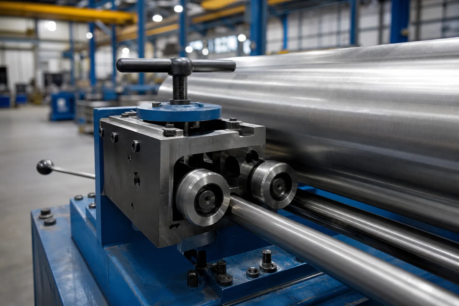
*Інженерна концепція ілюстрації.*
Випрямлення до та після нанесення покриття
Випрямлення до та після нанесення покриття або покриття обробляється як тема щодо контакту з поверхнею та інструментів, а не як окрема URL-адреса. Перевірити твердість покриття, контактне напруження та межі доопрацювання на сторінці інструментів для захисту поверхні та на сторінці відповідної заготовки перед вибором етапу правки.
Surface protection decisions like these show up directly on the finished part – в довідник міток інструментів covers contact damage in detail, і надмірне розпрямлення і розтріскування covers the deformation side of the same risk.