
Правка вала не є універсальним машинним процесом. Звичайний бар, ступінчастий вал двигуна, фланцева вісь, зубчастий вал трансмісії та довгий порожнистий ведучий вал можуть виглядати «зігнутими».,”, але вони не мають однакових функціональних даних, зони безпечного контакту, метод вимірювання або реакція корекції.
StraighteningTech оцінює проекти правки валів за кресленням заготовки, вхідна деформація, стадія процесу та спосіб приймання. Цей концентратор порівнює встановлені архітектури випрямлення валів і направляє запит; це не стверджує, що кожне перераховане сімейство деталей або архітектура машини входить до нашого поточного перевіреного асортименту поставок. Спеціальна можливість проекту, тривалість циклу та конфігурація обладнання можуть бути визначені лише після перегляду креслення, калібрувальна кореляція, репрезентативне тестування та оприлюднені результати приймання.
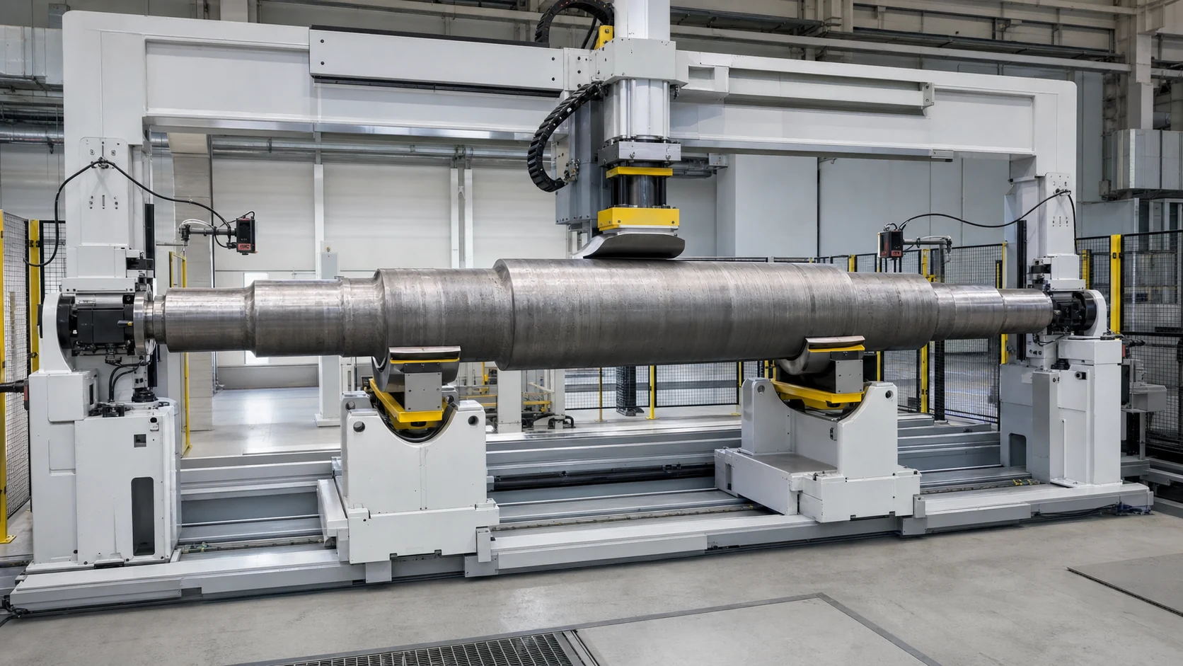
*Інженерна концепція ілюстрації. Це не поставлена машина, проект замовника, перевірена конфігурація датчика, точність або час циклу.*
Знайдіть правильний маршрут для свого вала
Почніть з геометрії та функції. Корисне питання не тільки «Який діаметр валу?», але «Які елементи визначають вісь у наступній операції обробки або складання?»
| Родина Шафт | Типові особливості | Первинний інженерний ризик | Ймовірний спосіб початку |
|---|---|---|---|
| Звичайний вал або заготовка бруска | Постійний діаметр, незавершена поверхня | Опора з великим прольотом і кілька вигинів | Роликовий випрямлення або точковий прес, залежно від довжини та допуску |
| Ступінчастий двигун або вал насоса | Шийки підшипників, сидіння ротора, плечі, шпонковий паз | Помилкове биття від неправильної бази даних; відмітки на готових журналах | Автоматичне вимірювання і правка точкового преса |
| Коробка передач або шліцьовий вал | Журнали, шестерні, сплайни, радіальні отвори | Функціональне биття, вимірювання зубів і зон, чутливих до тріщин | Багатоточкове вимірювання та контрольована точкова корекція |
| Вісь або фланцевий вал | Довге тіло, фланець, сплайн, нитка | Стабільне обертання, базова та асиметрична жорсткість фланців | Виділена підтримка, поворот і корекція точки |
| Черв'як, ходовий або кульковий гвинт | Потоковий функціональний розділ, журнали, струнка п'ядь | Порушення зонда, пошкодження різьблення та відскок | Реалізація даних, визначених кресленнями, наприклад затверджені журнали, центри або функціональний калібр — із захищеними зонами корекції |
| Розподільний або ексцентриковий вал | Частки, журнали та розділ зміни | Нерегулярні вимірювальні поверхні та локальні зміни жорсткості | Вимірювання з урахуванням функцій і корекція для конкретної моделі |
| Порожнистий приводний вал або труба | Тонка стінка, зварні шви, хомути або фланці | Згорнути, вм'ятини, співвідношення фаз і взаємодія балансу | Трубозахисний інструмент; випрямлення та балансування розглядаються окремо |
| Рульова рейка або асиметричний вал | Гладкі цапфи плюс зубчаста рейка | Некруглий перетин, функція перемикання передач і обмежені зони пресу | Підтримка з урахуванням профілю, вимірювання та корекція |
Якщо частина об'єднує кілька родин, найбільш чутлива функціональна функція контролює рішення. Порожнистий шліцьовий приводний вал, наприклад, не можна розглядати як простий круглий брусок.
Ці маршрути є скринінговими гіпотезами, не універсальні завдання. Малюнок, етап процесу, дозволені зони контакту та репрезентативні випробування визначають остаточний метод.
Визначте правильний розмір перед випрямленням
прямолінійність, кругове биття, повне биття та цеховий TIR пов’язані, але не взаємозамінні. Креслення має ідентифікувати керівну систему та редакцію ISO або ASME. Прямолінійність — це елемент керування формою, який не використовує зовнішню опорну базу. Кругове та загальне биття оцінюються відносно заданої базової осі; фізична опора та вісь обертання машини повинні бути показані для реалізації цієї бази даних.
| Вимоги до креслення | Що має бути узгоджено | Чому це важливо для машини |
|---|---|---|
| Прямолінійність осі або поверхні | Контрольована лінія, зона допуску та довжина оцінки | Визначає позиції вимірювання та мету корекції |
| Кругове биття | Вісь дат, поверхню зонда, осьова станція і один повний оберт | Контролює показання на заданій круговій ділянці |
| Повний витік | Вісь дат, контрольована поверхня, шлях зонда та правило обертання | Розширює оцінку на вказану поверхню |
| Цех TIR | Дата, станція або шлях, правило обертання та максимального–мінімального читання | TIR не слід вважати GD&T повне биття |
| Відношення журналу до осі даних | Точна характеристика малюнка, характеристики даних і контрольовані журнали | Уникає використання «коаксіальності» як невизначеної цехової заміни |
| Зубчаста або шліцьова функція | Метод кроку діаметра або функціонального калібру | Лише плавне вимірювання журналу може пропустити функціональну помилку |
| Поведінка остаточного складання | Підшипник, печатка, зчеплення, інтерфейси ротора або шестерні | Перешкоджає оптимізації зручного розміру, який не контролює збірку |
Перед котируванням, позначте кожну опору, зона вимірювання та пресування на кресленні. Також розмітьте шпонкові канавки, канавки, нитки, масляні отвори, поперечні отвори, часточки, зуби, тонкі стінки, зварні шви, покриття та остаточно відшліфовані поверхні, до яких не можна торкатися без дозволу.
Для результатів поблизу межі допуску, методи машини та замовника повинні документувати ту саму вимірювану величину та модель вимірювання, разом із застосовним правилом прийняття рішення щодо невизначеності та відповідності.
Точковий прес або роликове випрямлення?
Вибір залежить від геометрії, стадії процесу та методу приймання, а не на загальних перевагах для одного типу машини.
| Фактор прийняття рішень | Автоматичне випрямлення точкового преса | Роликове або наскрізне випрямлення |
|---|---|---|
| Найкраща стартова підгонка | Дискретні ступінчасті або багатофункціональні вали | Прутки постійного перетину, труб і заготовок валів |
| Вимірювання | Обертання за визначеними журналами з одним або кількома зондами | Офлайн або інтегроване вимірювання прямолінійності/биття |
| Виправлення | Локальний контрольований перевигин у затвердженому осьовому та кутовому положенні | Повторне згинання через розташовані валки |
| Захист функцій | Висока гнучкість для зон без тиску та підтримки | Обмежено, коли кроки, шестерні, фланці або готові елементи входять у рулони |
| Зміна моделі | рецепт, зміни підтримки та інструментів | Налаштування рулону, зміни напрямної та налаштування лінії |
| Типова перевага | Корекція замкнутого циклу, пов’язана з виміряним вигином | Безперервна обробка та ефективна обробка однорідного матеріалу |
| Основна потреба перевірки | Модель Springback, контактні позначки та максимальні межі корекції | Геометрія рулону, захист поверхні та повний результат |
Деякі виробничі маршрути використовують обидва методи на різних етапах. Заготівлю постійного діаметра перед обробкою можна випрямити роликом, в той час як готовий ступінчастий вал отримує корекцію на базі базової точки після термічної обробки або шліфування.
Процес автоматичного випрямлення валу із замкнутим циклом
Для багатофункціонального валу, загальною інженерною послідовністю є міра, розрахувати, виправте та переміряйте. Точні датчики, підтримує, для реального сімейства деталей вибрано модулі сили преса та автоматизації.
Відео демонструє одну автоматичну концепцію потоку матеріалу з невеликим валом і випрямлення преса. Він демонструє лише видиму структуру та послідовність обладнання; його публічні метадані не встановлюють ідентичність вала двигуна, тип датчика, сила, допуск або час циклу.
1. Визначте частину та виберіть перевірений рецепт
Пропонована рецептура визначає дату реалізації, опорні позиції, вимірювальні станції, дозволені зони корекції, цільова характеристика та максимальні межі корекції. Штрих-код, DMC або вибір виробничого замовлення – це необов’язкова архітектура, яка може зменшити помилки змішаної моделі, якщо її включити до підтвердженого обсягу проекту.
2. навантаження, Підтримуйте та обертайте вал
Ручне завантаження, піднос, конвеєр, robot або gantry є потенційними архітектурами обробки, а не областю за замовчуванням. Заготівля повинна стабільно обертатися в перевіреній опорі, яка реалізує задану базу даних. Центри, V-подібні опори, ролики та вісь обертання машини не є автоматично взаємозамінними.
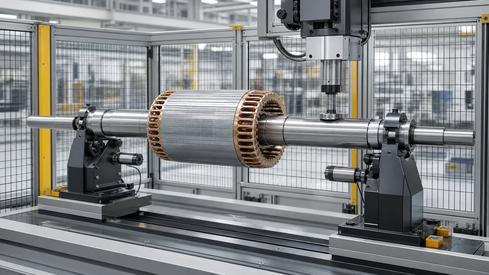
*Інженерна концепція ілюстрації. Геометрії є загальними прикладами скринінгу, не перевірені частини клієнта StraighteningTech або поточне покриття машини.*
3. Виміряйте вхідне відхилення
Контактні щупи, безконтактні датчики або функціональні датчики фіксують відхилення в затверджених положеннях. Система повинна відрізняти справжній вигин від забруднення, канавка, перехід діаметра або нестійке сидіння.
4. Обчисліть положення корекції та напрямок
Контролер визначає домінуюче осьове та кутове положення згину. Для валів з кількома вигинами, послідовність повинна уникати виправлення одного розташування та створення неприйнятного результату в іншому.
5. Застосуйте контрольоване надмірне згинання
Прес переміщується лише до схваленої зони та згинає вал за межі бажаного кінцевого положення, щоб еластична пружинна віддача залишала його ближче до мети. Інсульт і, де це доречно, межі сили розраховуються на основі реакції зразка.
6. Переміряйте та вирішіть
Знову використовуються ті самі датуми та вимірювальні станції. Якщо результат залишається за межами цільового значення, але залишається в межах підтверджених поправочних меж, може бути дозволена інша контрольована корекція. Частини, які досягають циклу, інсульт, сила або межа правдоподібності надсилаються до NOK або до інженерної перевірки.
7. Запис і вивантаження
Якщо відстежуваність включена в підтверджений обсяг контролю, налаштована клітинка може зберігати значення до/після, рецепт, кількість поправок і результат OK/NOK. Необхідний інтерфейс даних залишається предметом проектування та прийняття.
Захист функціональних елементів і поверхонь
Вал може відповідати значенню биття і залишатися непридатним для використання, якщо процес позначає шийку підшипника, пошкоджує нитку, спотворює порожнисту стіну або ініціює тріщину. Тому правила інструментарію та виправлення потребують плану захисту функцій.
| Особливість | Типовий ризик | Необхідний контроль |
|---|---|---|
| Заземлюючий підшипник або ущільнювач | Знаки опори або преса | Чисті контурні контакти та затверджений контактний тиск |
| Зуби шестерні або шліц | Пошкодження зуба або оманливий сигнал датчика | Функціональне вимірювання, якщо це необхідно; відсутність неконтрольованого контакту з пресою |
| шпонковий паз, паз або радіальний отвір | Концентрація напружень і зародження тріщин | Зона відчуження та межі консервативної корекції |
| Різьбова або черв'ячна секція | Пошкодження флангу та нестабільне вимірювання | Вимірюйте в затверджених журналах; захистити різьбову секцію |
| Фланець | Нестабільна опора або спотворення обличчя | Спеціальна концепція визначення місцезнаходження та підтримки |
| Порожнистий або тонкостінний профіль | Овальність, вм'ятини або руйнування | Розподілена підтримка та спеціальні інструменти для труб |
| Загартований перехід | Крихкий відгук або ризик розтріскування | Огляд твердості/партії, вибіркові випробування та межі зупинки |
| Покрита або готова поверхня | Косметичні або функціональні пошкодження | Сумісні контактні матеріали та контроль чистоти |
Одна платформа може охоплювати декілька моделей валів
Гнучка комірка може охоплювати сімейство валів під час руху машини, накладення сили та діапазону датчика та зміна інструментів можуть відтворити правильну базу. Покриття моделі має бути підтверджено по всьому конверту, не тільки за іменною пробою.
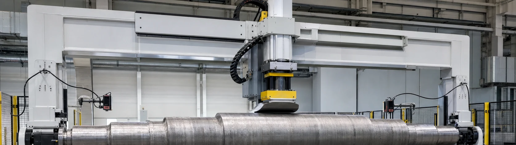
*Інженерна концепція ілюстрації. Він показує можливу домовленість про перевірку випущеного стану без вимоги даних, невизначеність, толерантність або прийнятний результат.*
| Модуль клітинки | Питання для вирішення |
|---|---|
| База машини і преса | Необхідний проїзд, вікно форсування/роздільності та доступ до корекції |
| Опори та обертання | Дата, проліт, захист поверхні та спосіб зміни моделі |
| Вимірювальна система | Тип датчика, кількість станцій, кореляція сили зонда та калібру |
| поводження | Інструкція, лоток, конвеєр, портальний або робот; орієнтація та розмір буфера |
| Елементи управління | Керування рецептами, модель корекції, обмеження зупинки та логіка аномальної частини |
| Дані про якість | Значення до/після, простежуваність, експорт і клієнтський інтерфейс |
| Безпека | Охорона, блокування, захист від перевантаження та доступ для обслуговування |
Шляхи застосування валу
Цей концентратор організовує запити на вал за деталлю, оскільки кожне сімейство має різні правила нулю та захисту елементів. Переглянуті опубліковані приклади наразі включають вали двигуна, автомобільні півосі та невеликі черв'ячні вали двигунів. Інші родини, включаючи текстильні вали, ходові або кулькові гвинти, приводні вали, ротори, роликові вали, колінчасті вали, розподільні вали та поршневі стрижні - залишаються маршрути оцінки, відповідність проекту яких має бути встановлено на основі прямих доказів та репрезентативних зразків. Залізничні осі, верстатні шпинделі та пластифікаційні гвинти тут не представлені як поточні верифіковані можливості StraighteningTech. Суцільний вал, Ідентифікація порожнистих труб і довгих прутів повинна бути підтверджена перед тим, як призначити циліндричну заготовку сімейству рішень.
Для перевірених опублікованих прикладів, побачити Рішення для автоматичного випрямлення вала двигуна, Рішення для випрямлення півосі автомобіля і Рішення для випрямлення черв'ячного вала малого двигуна. Кожен новий проект все ще потребує власного креслення та перегляду зразка.
Перевірка зразка перед остаточною пропозицією
Репрезентативні випробування перетворюють концепцію машини на специфікацію проекту, яку можна захистити. Зразок повинен включати короткий/довгий, малий/великий діаметр, нормальний/найгірший вхідний вигин, і відповідні партії матеріалів або термічної обробки.
| Елемент перевірки | Докази для запису |
|---|---|
| Угода про обмір | Дата, положення зонда, вимірювальний метод і результат кореляції |
| Вхідний стан | Розподіл вигинів, стан поверхні та аномальні зразки |
| Виправна відповідь | Відповідь на удар/силу, пружинний відкат і корекційний рахунок |
| Остаточний результат | Всі необхідні вимірювальні станції, не тільки найгірший початковий момент |
| Цілісність частини | Контактні позначки, тріщини, стан різьби/зуба/фланця та інші ризики |
| Виробнича придатність | Завантаження, перехід, розподіл циклу, Обробка NOK і потреби в даних |
| Межа приймання | Сімейство перевірених деталей і умови, на які поширюється остаточна пропозиція |
Жодна вимога щодо універсальної точності чи часу циклу не стосується кожного валу. Остаточна гарантія повинна вказувати сімейство деталей, етап процесу, вхідний діапазон, дані, метод вимірювання, зразки доказів та умови прийняття.
Інформація, необхідна для пропозиції випрямлення валу
Будь ласка, надайте:
- 2Д креслення і, якщо є, 3D модель;
- матеріал валу, твердість і стан термічної обробки;
- мінімальний/максимальний діаметр, довжина і матриця моделі;
- центри, підшипникові шийки, сидіння ротора, шестерні, сплайни, фланці, нитки та інші функціональні особливості;
- розподіл вхідного вигину або биття, включаючи найгірші випадки;
- необхідна характеристика, терпимість, дані та метод перевірки замовника;
- дозволена підтримка, зони вимірювання та пресування;
- чутливі поверхні та заборонені зони контакту;
- поточний етап процесу та наступний етап виробництва або складання;
- обсяг виробництва, цільова година такту, напрямок завантаження та потреби в зміні;
- репрезентативні зразки, що охоплюють повну родину.
FAQ
Чи може одна машина для правки валу впоратися з кожним типом вала?
немає. Платформа може охоплювати підтверджену сім’ю під час її подорожі, сила, датчики, опори та інструменти відповідають повному конверту. Пристосований, фланцеві, порожнистий або дуже тонкий вал може потребувати іншої концепції вимірювання або корекції.
Прямолінійність те саме, що і МДП?
немає. Прямолінійність — це незалежний від даних елемент керування формою. Показання МДП – це максимальна–мінімальна індикація цеху, дата якої, зондова станція або шлях, правила обертання та читання повинні бути задокументовані; це не автоматично GD&T повне биття. Креслення та метод вимірювання замовника повинні визначати, що вимірює та приймає машина.
Якщо вал ступінчастий, використовуйте роликовий випрямляч?
Роликова правка є загальним початковим кандидатом для матеріалу постійного перерізу. Після завершення функціональних функцій, натомість ступінчастий вал може вимагати вимірювання на основі даних, захищені контактні зони та локальна точкова корекція; креслення та випробування зразків визначають маршрут.
Чи можна випрямити загартовані вали без тріщин?
Це може бути здійсненним, але твердість, геометрія, концентрація напруги та вхідний вигин змінюють ризик. Межі консервативної корекції, мають бути узгоджені репрезентативні випробування та вимоги до перевірки тріщин або поверхні.
Чи замінює вирівнювання валу балансування?
немає. Рихтування контролює геометрію або биття; балансування контролює розподіл маси під час обертання. Привідний вал або ротор можуть потребувати обох процесів, із визначеною послідовністю та окремими критеріями прийнятності.
Як найшвидше отримати корисну пропозицію?
Надішліть малюнок, матеріал/твердість, вхідні та цільові вимірювання, дані, охоронні зони, вимоги до виробництва та репрезентативні зразки. Це дозволяє групі інженерів рекомендувати процес і концепцію машини замість того, щоб здогадуватися про діаметр і довжину.
Побудуйте рішення із заготовки
Надійним шляхом є класифікація заготовок, визначення вимірювання, вибір методу, дизайн захищеної зони та валідація зразків. Це запобігає вибору машини на основі неповного твердження допуску або зручної, але нефункціональної бази даних.
Зверніться до StraighteningTech з вашим кресленням валу та інформацією про зразок. Наша команда рішень може підготувати запропоновані вимірювання, корекція, концепція обробки та перевірки для інженерного огляду; Остаточний обсяг залишається підлягаючим перевірці креслення та зразка.
Межа технічного посилання
Цей центр використовує загальнодоступні технічні матеріали зі структур специфікацій розмірів ISO/ASME та визнаних виробників рихтувальних машин для опису галузевої термінології, сімейства заготовок і можливі архітектури процесу. Ці джерела не підтверджують асортимент машини StraighteningTech, датчики, алгоритми керування, точність, час циклу, функції відстеження або історію доставки. Претензії щодо конкретного проекту вимагають креслень StraighteningTech, записи конфігурації, репрезентативні випробування та опубліковані докази прийняття.