
Кілька показань об’єму можуть перетворити перевірку довгого валу з одного піку на карту помилок. Це значення залежить не лише від датчика: опорна геометрія, опорне положення, контакт зонда, ротація/індексація, синхронізація, умови навколишнього середовища та правило обчислення впливають на те, що повідомляється.

*Інженерна концепція ілюстрації. Це не специфікація датчика, встановлена система або перевірений результат вимірювання.*
Визначте характеристику перед вибором датчиків
Спочатку вкажіть, чи є приймальна характеристика прямолінійністю центральної лінії, місцевий лук, биття відносно опорної точки, відхилення профілю або інший контрольований результат. Напруга чи зміщення датчика самі по собі не є вимогою замовника. У плані перевірки повинні бути визначені базові характеристики, підтримує, станції, орієнтації, проліт, розрахунок, одиниць, межі та стан, у якому частина прийнята.
| елемент | Питання на закриття |
|---|---|
| Дата | Які елементи встановлюють опорну вісь або поверхню? |
| Підтримка | Чи повторює він стан замовника або випущеної частини? |
| Зондовий шлях | Чи мають контактні точки функціональні поверхні та захищені від пошкоджень? |
| Станції | Чи фіксують вони відомі зони вигинів і переходи елементів? |
| Ротація/індексація | Як зберігається орієнтація між читаннями? |
| Розрахунок | Як показання перетворюються в контрольовану характеристику? |
Для контрольних елементів, побачити очищення центрального отвору валу та підготовка бази і повторюваність кріплення та посадка бази.
How an LVDT Works, and Why Its Physics Matters
The linear variable differential transformer earns its place on production machinery through a short list of physical virtues. Inside the housing, a primary coil is excited with an alternating current, and two secondary coils sit either side of it; a ferromagnetic core, attached to the probe tip by a slim push rod, slides along the axis. With the core centered, the induced voltages in the two secondaries balance; displace the core and the balance tips in proportion to the movement. The electronics read the amplitude and phase of that imbalance and report displacement. Because the core never touches the coils, there is no friction or wear inside the sensor; because the coupling is inductive, the reading is largely indifferent to dust, oil mist and humidity that blind optical sensors; and because the moving mass is small, the tip can follow moderate surface motion faithfully. The trade-offs are equally physical: it needs signal conditioning and calibration against a reference, the raw output is relative rather than absolute, and the probe tip itself is a mechanical component with its own condition, force and wear story.
Where Errors Enter Between Probe and Number
Treating the chain as one system, as the section above demands, means knowing the specific doors through which error walks in. Thermal drift: the sensor body, the fixture and the part all expand and contract with temperature, and on a machine that warms through a shift, a morning zero and an afternoon reading are not the same event — hence reference checks on a master at intervals the procedure defines. Mounting: a probe on a long, unsupported bracket is a cantilever with its own compliance, and vibration or cable pull moves the whole assembly relative to the part, indistinguishable from part movement in the data. Dynamics: when the part or probe moves during scanning, the stylus mass and tip force set a speed limit beyond which the tip skips or lags, writing false features into the trace. Contact condition: tip wear flattens the intended radius and changes where the reading sits on a curved surface. None of these is exotic; each is controlled by written procedure — zero method, master check interval, scan speed, tip inspection — which is precisely what the validation framework above asks the system description to contain.
Розглядайте ланцюжок вимірювань як одну систему
LVDT може підійти для відносного зміщення, але результат вимірювання також включає встановлення датчика, прогин кріплення, формування сигналу, терміни, розміщення частини та поведінка оператора чи автоматизації. Запишіть кожен елемент у ланцюжку, щоб можна було дослідити пізніший зсув результату.
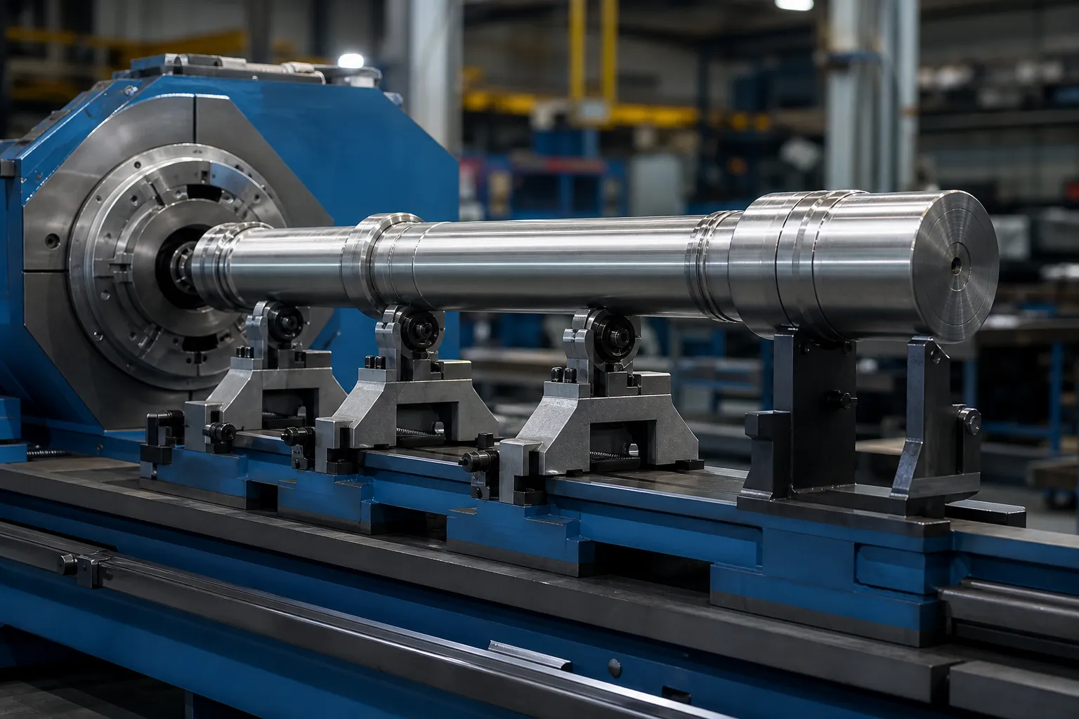
*Інженерна концепція ілюстрації. Жорсткість кріплення, Розташування датчика та захист вимагають спеціального проектування.*
Контрольована процедура повинна охоплювати ідентифікацію датчика, референс/майстер перевірка, стан кріплення, захист кабелю, нульовий метод, орієнтація зразка, підтримувати чистоту, налаштування збору та збереження даних. Повторне зчитування з нестабільного приладу не є доказом повторюваності.
Синхронізувати місцезнаходження, Орієнтування та читання
Багатоточкові дані корисні лише тоді, коли кожне значення можна призначити відомому положенню та умові. Якщо деталь обертається або рухається, визначте кодер/індекс, координати станції, напрямок руху, умови перебування або відбору проб, і що станеться, якщо сигнал відсутній. Результат має зберегти необроблені або простежувані вихідні дані, необхідні для реконструкції карти.
Уникайте інтерпретації локалізованого піку без перевірки посадки та контакту. Переставити тести, зворотна орієнтація, де це доречно, і повторне зчитування базової лінії можуть відрізнити функцію частини від помилкової індикації.
Choosing Station Count and Placement
How many stations, and where, is a geometry question before it is a budget question. The error modes of slender parts are smooth in space: a bend is a low-frequency curve, so a modest number of stations — placed where the physics says the information lives — reconstructs it well, while doubling the count in uninformative positions buys data volume, not accuracy. Informative positions are predictable: mid-span between supports where a bow reaches its excursion; each stiffness transition on stepped parts, where peaks like to hide; immediately beside functional features whose relationship to the datum matters; and the free ends, which anchor the map. The failure mode of sparse placement is aliasing in its practical form — a short kink sitting between two stations contributes to neither reading cleanly, and a correction aimed at the reconstructed map presses in the wrong place. The honest way to close this risk is not infinite density but a validation: map a set of parts at high density once, confirm that the production station set reconstructs the same peaks and amplitudes, and document that comparison as the station-plan justification.
Turning the Map Into a Correction Decision
The map exists to drive action, and its action vocabulary has three entries: where to press, in which direction, and how hard to expect the part to respond. Peak position and direction come from comparing stations around the maximum; on a part rotating between stations, preserving angular indexing — the synchronization discipline above — is what converts separate readings into a vector, not a pile of magnitudes. Expected response comes from the stiffness story the map already tells: a peak on a heavy section needs a different correction plan than the same amplitude on a thin one, and peaks at stiffness transitions deserve the respect described for separating bend from roundness and setup effects before any press follows. What the map must not do is trigger correction on unverified signals: a localized reading that has not survived a reseat check is a hypothesis, not a peak. That guard rail — map, перевірити, then correct, with released-state measurement closing the loop — is the same sequence that makes автоматичне рихтування валу converge in few strokes instead of many.
Співвідносяться з прийняттям випущеної частини
Вимірювання під час затискання або корекції може бути корисним для контролю процесу, але це автоматично не доводить, що звільнений вал відповідає вимозі. Порівняйте лінійний метод із схваленим методом звільненої частини на репрезентативних зразках у межах нормальних варіацій. див вимірювання прямолінійності під навантаженням і у відпустці за кордон.
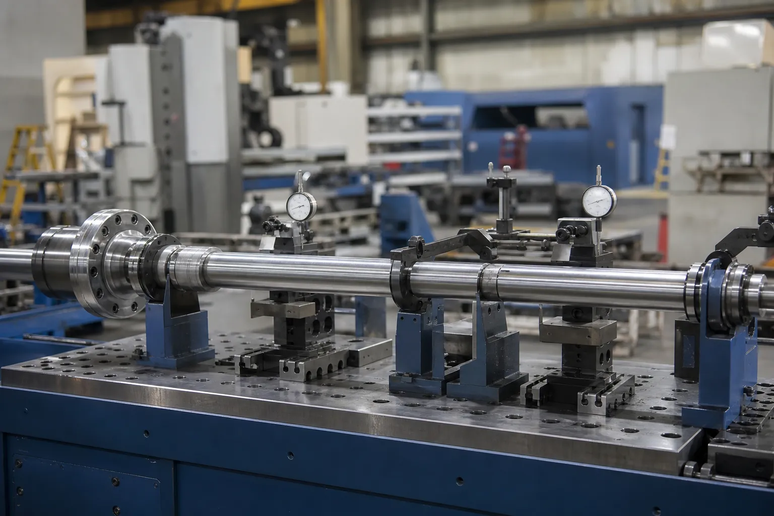
*Інженерна концепція ілюстрації. Довідковий метод, опори та приймальні розрахунки повинні контролюватися затвердженим планом якості.*
План кореляції повинен визначати відповідні вибірки, сліпе порівняння, де це можливо, еквівалентність бази даних/опори, стан калібрування, огляд упередженості, перевірка повторюваності/відтворюваності, дозволена різниця, правила ескалації та контролю змін. Зверніться до кореляція вимірювання машини та вимірювання клієнта і Гейдж Р&R для випрямлення ліній.
Вхідні дані, необхідні для дослідження вимірювань
Надайте малюнок і визначення характеристики, існуючий метод перевірки, геометрія деталі та базові характеристики, матеріал/етап виготовлення, очікувані місця вигину, вибіркова сукупність, екологічні обмеження, бажаний запис даних і спосіб прийняття клієнтом. Використовуйте випробування зразків вирівнювання та посібник із приймання для встановлення протоколу судового засідання, потім зверніться до StraighteningTech для обговорення заявки.
Необхідна перевірка перед системною претензією
Any multi-point measurement claim needs a defined probe and datum setup, калібровані еталони, repeated or reseated readings on representative parts, and customer-gauge correlation. A generic machine capability is not a verified result.
FAQ
Does adding more measurement stations automatically improve accuracy?
немає. Stations placed where the geometry has information — mid-span peaks, stiffness transitions, functional features, ends — improve the map. Stations added elsewhere add data volume and cost while leaving reconstruction essentially unchanged. Validate the chosen set once against a dense map and document the comparison.
Why do LVDT readings drift over a production shift?
Most often thermal: датчик, fixture and part expand at different rates as the cell warms, shifting the zero. Mechanical causes come next — bracket compliance, cable pull, tip wear. The control is procedural: a defined zero method and reference-master checks at set intervals, with any shift beyond the procedure’s limit triggering investigation rather than quiet re-zeroing.
Can multipoint LVDT data replace final inspection?
Only through correlation. In-process multipoint data drives the correction loop; the acceptance decision belongs to the released-state method the customer recognizes. When the two have a documented correlation on representative parts, the line method gains standing — until then it is process control, not release.
Пов’язані ресурси StraighteningTech
див як працює автоматичне рихтування валу, випробування зразків випрямлення та прийняття і прямолінійність вала проти биття проти TIR для загальних меж контролю, які застосовуються до будь-якої претензії на можливості LVDT Багатоточкове вимірювання валу.
Multipoint measurement pays off at acceptance time – pair the Контрольний список FAT with the GD&T straightness acceptance guide to agree measurement method and tolerance interpretation in one pass.