
İnce duvarlı tüpler bükülebilir, oval, aynı anda yerel olarak çentikli veya bükülmüş. Borunun merkez çizgisini iyileştiren bir işlem, kesiti daraltırsa yine de başarısız olabilir, duvarı buruşturur, yüzeyi işaretler veya kaynak dikişine zarar verir.
İnce duvarlı bir boru doğrultma çözümü bu nedenle hem küresel geometriyi hem de yerel kesit bütünlüğünü kontrol etmelidir. Çizimle başlar, boru yapımı ve üretim aşaması — genel bir baskı kuvveti veya silindir ayarıyla değil.
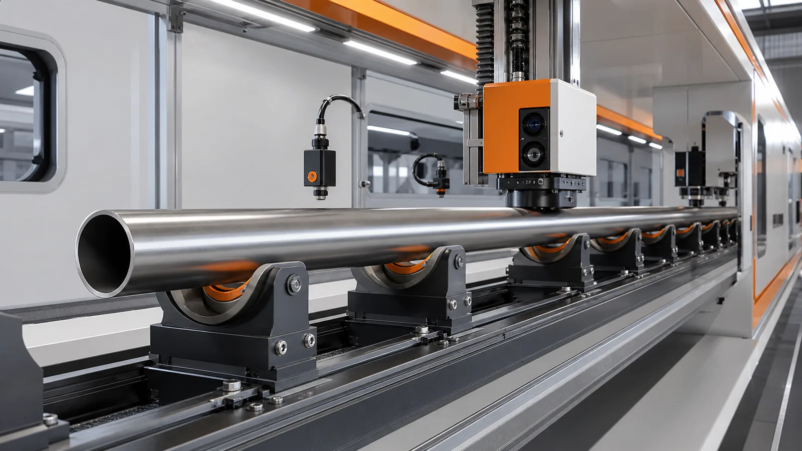
Bu bir mühendislik konsepti illüstrasyonudur, müşteri sitesi fotoğrafı değil. Gerçek destekler, sensörler ve düzeltme takımları boru çapına bağlıdır, duvar kalınlığı, malzeme, bölüm ve örnek testler.
İnce Duvarlı Borular Neden Farklıdır?
| Tüp Özelliği | Riskin Düzeltilmesi | Mühendislik Yanıtı |
|---|---|---|
| İçi boş bölüm | Harici düzeltme tüpü düzleştirebilir veya daraltabilir | Kontrol kontak geometrisi, baskı ve iç destek ihtiyacı |
| Çapa göre küçük duvar kalınlığı | Yararlı düzeltmeden önce yerel bükülme ve buruşma meydana gelebilir | En kötü durum numunelerinde gerinim ve destek aralığını doğrulayın |
| Mevcut ovallik | Döndürme ölçümü form hatasını bükmeyle karıştırabilir | Merkez çizgisini ve kesit şeklini ayrı ayrı ölçün |
| Kaynak dikişi | Dikiş sertliği ve hasar riski açısal konuma göre değişebilir | Dikişi tespit edin/indeksleyin ve korunan sektörleri tanımlayın |
| Bitmiş dış yüzey | Silindirler veya pres araçları çentikler ve tanık izleri oluşturabilir | İletişim materyalini onayla, Genişlik, temizlik ve yüzey kriterleri |
| Uzun esnek uzunluk | Sarkma ölçülen eğriyi değiştirir | Destek aralığını dondur, oryantasyon ve sarkma tedavisi |
| Bükülmüş/konik/kademeli boru | Düz dönüş ve tek biçimli takımlama geçerli olmayabilir | Bölüme özel destekleri ve istasyon haritalarını kullanın |
| Açık uçlar | Uç bölümler daha kolay deforme olur | Minimum kullanılabilir uç mesafesini ve uç desteğini tanımlayın |
Proje hiçbir zaman tek başarı kriteri olarak “başarılan doğruluk”u kullanmamalıdır.. Kesit ve yüzey durumu, üzerinde anlaşılan sınırlar dahilinde kalmalıdır.
Bir Yöntem Seçmeden Önce Kusurları Ayırın
Merkez Çizgisi Bükümü
Boru ekseni veya merkez çizgisi uzunluğu boyunca sapıyor. Bu sıradan bükme düzeltmenin birincil hedefidir.
Ovallik ve Lokal Düzleşme
Kesit artık yeterince yuvarlak değil. Ovallik önceden var olabilir, kenetlemeden kaynaklanır veya temasın düzeltilmesiyle oluşturulur.
Yerel Göçük veya Çökme
Konsantre bir yük yerel olarak içe doğru bir deformasyona neden olur. Merkez hattı bükülmesinin iyileştirilmesi bu hasarı otomatik olarak ortadan kaldırmaz.
Kırışma veya Bükülme
İnce bir duvarın basınç tarafı, düzeltme gerilimi çok yüksek olduğunda veya yeterince desteklenmediğinde dalgalar veya yerel bir bükülme oluşturabilir.
Büküm
Yuvarlak borular, özellikler içermedikçe bükülmeyi gizleyebilir, dikişler, delikler veya ekli braketler. Dikdörtgen ve şekilli borular, açık burulma ölçümü ve farklı bir düzeltme stratejisi gerektirir.
Kaynak Bozulması
Boyuna dikişler, uç kaynaklar veya eklenen bağlantı parçaları asimetrik deformasyona ve yerel güç farklılıklarına neden olabilir. Kaynaklı düzenekler tekdüze ham boru olarak değerlendirilmemelidir.
Dondurucu Tüp Yapımı ve Proses Aşaması
Çözüm, iş parçasının olup olmadığını tanımlamalıdır.:
- dikişsiz veya uzunlamasına kaynaklı;
- yuvarlak, oval, kare, dikdörtgen veya başka bir profil;
- düz ham tüp, boyuna kesilmiş boş veya şekillendirilmiş parça;
- tavlanmış, ısıl işlem görmüş, kaplamalı, cilalanmış veya başka şekilde tamamlanmış;
- boş, dahili bileşenlerle veya kaynaklı bir düzeneğin parçasıyla donatılmış;
- işlemeden önce veya sonra, bükme, kaynak veya yüzey işleme.
Ham bir boruyu bitirmeden önce düzeltmek, cilalanmış bir otomotiv borusunu veya bir boruyu düzeltmekten farklı yüzey ve pay kurallarına sahiptir. kaynaklı soğutma manifoldu. Later processing can reintroduce distortion, so the route may require more than one controlled geometry check.
Define Global and Local Acceptance Together
| karakteristik | What It Controls | Why It Must Be Separate |
|---|---|---|
| Axis/centerline straightness | Global tube path | Does not prove the cross-section stayed round |
| Circular/total runout | Rotational variation relative to a datum | Includes reference and section-form effects |
| Dış çap | Local size | Can change during flattening or expansion |
| Ovality/roundness | Cross-section shape | Direct collapse indicator for round tubes |
| Duvar kalınlığı | Section strength and forming response | May vary around welded or drawn tube |
| Yüzey durumu | Ezikler, çizikler, coating or cosmetic marks | Independent of centerline result |
| Seam condition | Weld integrity and location | Can control orientation and correction limits |
| Büküm | Angular change along shaped/featured tube | Not captured by one radial probe |
The drawing and customer gauge must define stations, veri, destek koşulu, filters and decision rules. Gözden geçirmek Mil Düzlüğü - Salgı - TIR before interpreting a rotating indicator signal as tube straightness.
Measure Centerline and Ovality Separately
A single contact probe on the outside diameter cannot always distinguish a bent but round tube from a straight but oval tube. Multiple angular readings, opposing sensors, diameter scans or a suitable non-contact system may be required.
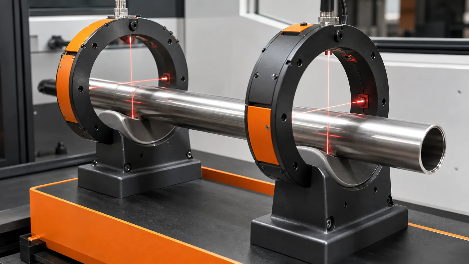
This engineering concept illustration shows non-contact centerline and diameter measurement. It does not prescribe optical sensors for every tube.
| Ölçüm Elemanı | Proje Tanımı |
|---|---|
| Datum/reference | Ends, dergiler, fittings, mathematical axis or customer fixture |
| Axial stations | Global curve points plus high-risk local sections |
| Angular coverage | Enough directions to separate bend and ovality |
| Support plan | Sayı, açıklık, height and contact pressure |
| Seam indexing | Seam angle at measurement and correction stations |
| Probe method | Contact force or non-contact range/resolution |
| End exclusion | Minimum distance from unsupported/open ends |
| Serbest bırakılma durumu | Measurement only after external/internal correction load is removed |
For non-round tube, the system may need multiple faces, edges or section-specific coordinates rather than simple rotational runout.
Support the Tube Without Creating the Defect
Supports must hold and move the tube while keeping contact pressure below the validated local deformation limit.
Important variables include:
- saddle radius and conformity to the actual OD;
- roller width and edge radius;
- sleeve/pad material and embedded-particle risk;
- support span and intermediate support positions;
- tube rotation or axial-feed force;
- clamping pressure and grip length;
- open-end support and minimum contact distance;
- weld-seam angle relative to contacts;
- cleaning and tooling-inspection frequency.
A soft pad can still dent a tube if the contact area is too small or contamination is trapped beneath it. Tooling must be validated on the minimum wall thickness and weakest included material condition.
Pres Doğrultma ve Rulo Doğrultma
| Rota | Strong Starting Fit | Main Thin-Wall Risk |
|---|---|---|
| Lokalize basın düzleştirme | Ayrık bükülme bölgeleri, feature-rich parts, low/medium mix | Local flattening, denting and compression-side wrinkle |
| Multi-roll/continuous straightening | Long uniform tubes with distributed curvature | Repeated contact, ovality growth, end effects and surface marking |
| Moving-frame correction | Long tubes where moving the part is difficult | Support transitions and station correlation |
| Internal-support-assisted correction | High collapse risk at known local zones | Mandrel insertion, yerleştirmek, friction and removal |
| Hybrid process | Pre-straighten stock then targeted final correction | Clear acceptance and responsibility at each stage |
Kullanmak Pres Doğrultma ve Rulo Doğrultma for the general method decision. Thin-wall tube selection adds section-stability and surface constraints.
Internal Support: Option, Not Default
An internal mandrel, expandable support, plug or local backing device can reduce collapse at the correction zone. It also introduces new risks.
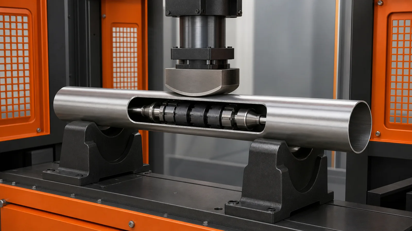
This cutaway engineering concept illustrates one possible internal-support arrangement. It is not a universal production design.
| Internal-Support Question | Neden Önemlidir? |
|---|---|
| Can the device enter and reach the correction zone? | Bends, uzunluk, fittings and closed ends may block access |
| What is the support clearance? | Too loose gives little support; too tight can score or jam |
| How is it positioned? | The internal support must align with the external load zone |
| Is it fixed or expandable? | Expansion force can itself change diameter/ovality |
| What is the contact material? | Internal surface scratches or contamination may be unacceptable |
| How is it removed? | Geri yaylanma, burrs or deformation can trap the device |
| Can several stations be corrected? | Moving the support affects cycle and control complexity |
| How is internal condition inspected? | Damage may not be visible from outside |
Alternative approaches can include broader external tooling, lower incremental correction, hydro/pneumatic support where appropriate, or moving the straightening operation to an earlier process stage. Each requires its own safety and validation plan.
Weld Seam and Feature Indexing
For welded tubes, seam position can affect stiffness, measurement and damage risk. The recipe should define whether the seam is:
- detected automatically or oriented manually;
- permitted under a support or press tool;
- excluded from high-strain correction sectors;
- measured for local profile or integrity;
- tracked through the entire cycle.
Delikler, yuvalar, beads, parantez, flares, swages and end fittings also change local stiffness. An ordinary OD sensor or press tool should not cross these features without a defined method.
Kontrollü Düzeltme ve Geri Yaylanma
Localized correction should use a validated span and broad conforming contacts. The machine applies only enough controlled over-bend to obtain permanent correction after release.
The recipe should bound:
- support and correction coordinates;
- seam/feature angular orientation;
- maksimum kuvvet, strok ve yüklü deplasman;
- maximum section deformation during loading;
- correction increment and attempt count;
- reverse-correction or oscillation rules;
- internal-support state and position;
- post-release straightness, ovality and surface checks.
Final acceptance must be measured after the external load and any internal expansion force are fully released. Görmek Şaft Düzeltmede Geri Yaylanma Telafisi for bounded iteration and stop logic.
Savunulabilir Bir Otomatik Döngü
- Identify tube family, çizim, construction and process-stage recipe.
- Confirm diameter/section, wall range, material and seam/feature condition.
- Clean the tube and inspect external/internal support tooling.
- Load on broad validated supports and locate the tube axially.
- Detect or index seam and prohibited features where required.
- Measure centerline and cross-section characteristics at agreed stations.
- Separate sag, ovality and local dents from correctable global bend.
- Select the approved correction method, span and optional internal support.
- Apply bounded correction while monitoring force/stroke and section risk.
- Fully release external/internal loads and restore the measurement condition.
- Remeasure centerline, ovality/section and surface/seam criteria.
- Record results and route to OK, recheck, secondary operation or NOK.
Yuvarlak, Rectangular and Formed Thin-Wall Tubes
| Tube Family | Additional Control |
|---|---|
| Round seamless tube | Bend/ovality separation and end collapse |
| Longitudinally welded round tube | Seam indexing and integrity |
| Square/rectangular tube | Face flatness, corner radii, twist and wall buckling |
| Oval/formed section | Section-specific supports and measurement model |
| Bent tube assembly | 3D datum, tangent/angle and local bend geometry |
| Tube with fittings | Grip/feature protection and access for internal support |
| Multi-channel/extruded tube | Internal webs, torsion and local crush behavior |
| Coated/polished tube | Surface contact and cosmetic standard |
These families should not share an unvalidated universal recipe.
Makine ve Veri Modülleri
| Modül | Proje Tanımı |
|---|---|
| Yükleme/aktarma | Manuel, konveyör, portal veya robot; anti-sag handling |
| Parça tanımlama | Bölüm, wall/material family and wrong-recipe prevention |
| Seam/feature detection | Camera, sensör, fixture or manual index |
| Destek hattı | Saddle/roller geometry, açıklık, setup and wear monitoring |
| Ölçüm | Merkez çizgisi, diameter/ovality, twist and local-section stations |
| Düzeltme | Basmak, silindirler, moving frame or hybrid process |
| Internal support | Tip, konumlandırma, expansion, insertion and removal |
| Surface/seam inspection | External and internal criteria after correction |
| İzlenebilirlik | İlk harita, düzeltme geçmişi, final map and reject reason |
| Kaliteli arayüz | Customer gauge correlation and reference-master checks |
Örnek Test ve Kabul Matrisi
| Test Grubu | Temsili Örnekler | Evidence Required |
|---|---|---|
| Diameter/wall range | Largest diameter with thinnest wall plus boundaries | Collapse and tooling envelope |
| Material/condition | Softest, strongest and finished states | Geri yaylanma, wrinkle and surface response |
| Welded/seam variants | Seam angles and weld batches | Indexing and integrity result |
| Length/bend range | En kısa/en uzun, good/borderline/worst incoming | Destek, sag and correction map |
| Enine kesit | Round plus every approved shaped family | Dedicated gauge/tooling result |
| End/features | Açık uçlar, delikler, fittings and formed zones | Exclusion and local support rules |
| Internal support | Insertion/position/removal extremes | No jam or internal damage |
| Gösterge korelasyonu | Same parts on machine and customer method | Telafi etmek, tekrarlanabilirlik ve karar anlaşması |
Şunu kullanın: Doğrultma Numune Testi ve Kabul Kılavuzu fizibiliteyi tanımlamak, FAT ve SAT kanıtı.
Information Required for a Thin-Wall Tube Proposal
Lütfen sağlayın:
- complete tube/assembly drawing and revision;
- seamless/welded construction and seam specification;
- malzeme, temper/heat treatment and process stage;
- round or shaped section, OD/width/height, wall thickness and length range;
- bükülmek, dürüstlük, salgı, ovallik, çap, twist and surface requirements;
- datum/reference, measuring stations and customer fixture;
- incoming bend/ovality/dent distribution and representative rejects;
- delikler, yuvalar, Kaynaklar, fittings, bends, flares and prohibited zones;
- approved external and internal contact surfaces;
- cosmetic, kaplama, seam and internal-surface acceptance criteria;
- access and clearance available for internal support;
- hedef verim, yükleme yöntemi, geçiş ve izlenebilirlik;
- temsili iyi, sınırda ve NOK örnekleri.
Our engineering team can then define the support model, measurement architecture, düzeltme yöntemi, optional internal tooling and validation matrix. Nihai doğruluk, cycle time and section integrity must be confirmed on the actual tube family—not copied from a generic tube-straightening claim.
Sıkça Sorulan Sorular
Can a standard bar straightener be used for thin-wall tube?
Not without validation. A tube is hollow and can collapse, ovalize or wrinkle under contact loads that a solid bar tolerates.
Is straightness enough to accept the tube?
HAYIR. ovallik, çap, local dents, yüzey durumu, seam integrity and twist may also control acceptance.
Does internal support always prevent collapse?
HAYIR. Clearance, konum, expansion, contact material and removal all matter. The support can introduce its own damage or dimensional change.
Can an ordinary contact probe measure tube bend?
It may combine bend, ovallik, surface form and support effects. The project must define enough angular/station information to separate them or use another suitable method.
Should the weld seam face away from the press?
There is no universal orientation rule. Seam design, malzeme, weld condition and load path must be reviewed and tested before the recipe fixes an angle.
Which is better for thin-wall tube: rollers or press straightening?
It depends on section, curvature distribution, surface stage and collapse risk. Rollers suit some uniform long tubes; localized press correction suits some discrete defects. Both require tube-specific tooling.
Is final geometry checked with the internal support still expanded?
HAYIR. Final acceptance should use the released tube in the agreed measurement condition unless the drawing explicitly defines another state.
Can round and rectangular thin-wall tubes share one setup?
Otomatik olarak değil. Rectangular tubes add face, corner and torsion behavior and need section-specific supports, measurement and correction tools.
Every thin-walled pipe straightening project eventually hits the same two questions – the düzleştirici seçim kılavuzu ve limits of over-straightening answer them before your supplier meeting does.