
Kılavuz vidalar, aktüatörlerde dönme hareketini kontrollü doğrusal harekete dönüştürür, konumlandırma sistemleri, kompakt otomasyon ve step motor düzenekleri. Küçük bir bükülme radyal salgı yaratabilir, düzensiz somun hareketi, gürültü, ilave yatak yükü veya montaj zorluğu. Çünkü iplik hem işlevsel bir yüzey hem de zor bir temas geometrisidir, kurşun vida düz yuvarlak çubuk gibi ele alınamaz.
Önerilen bu kurşun vida düzeltme çözümü tekrarlanabilir veri desteğini birleştirir, dönme ölçümü, korumalı nokta basma ve tam yeniden ölçüm. Birbirinden çok farklı iki aday parça ailesi için müşteri bilgilerine dayanmaktadır: kısa Ø6,35 × 75 mm vida ve Ø3,5 olarak bildirilen dört numune parçası × 508 mm. Bu boyutlar yaklaşık olarak uzunluk-çap oranları oluşturur 11.8 Ve 145.1, dolayısıyla varsayılan tek bir makine tarifi yerine ayrı fizibilite pencereleri gerektirirler.
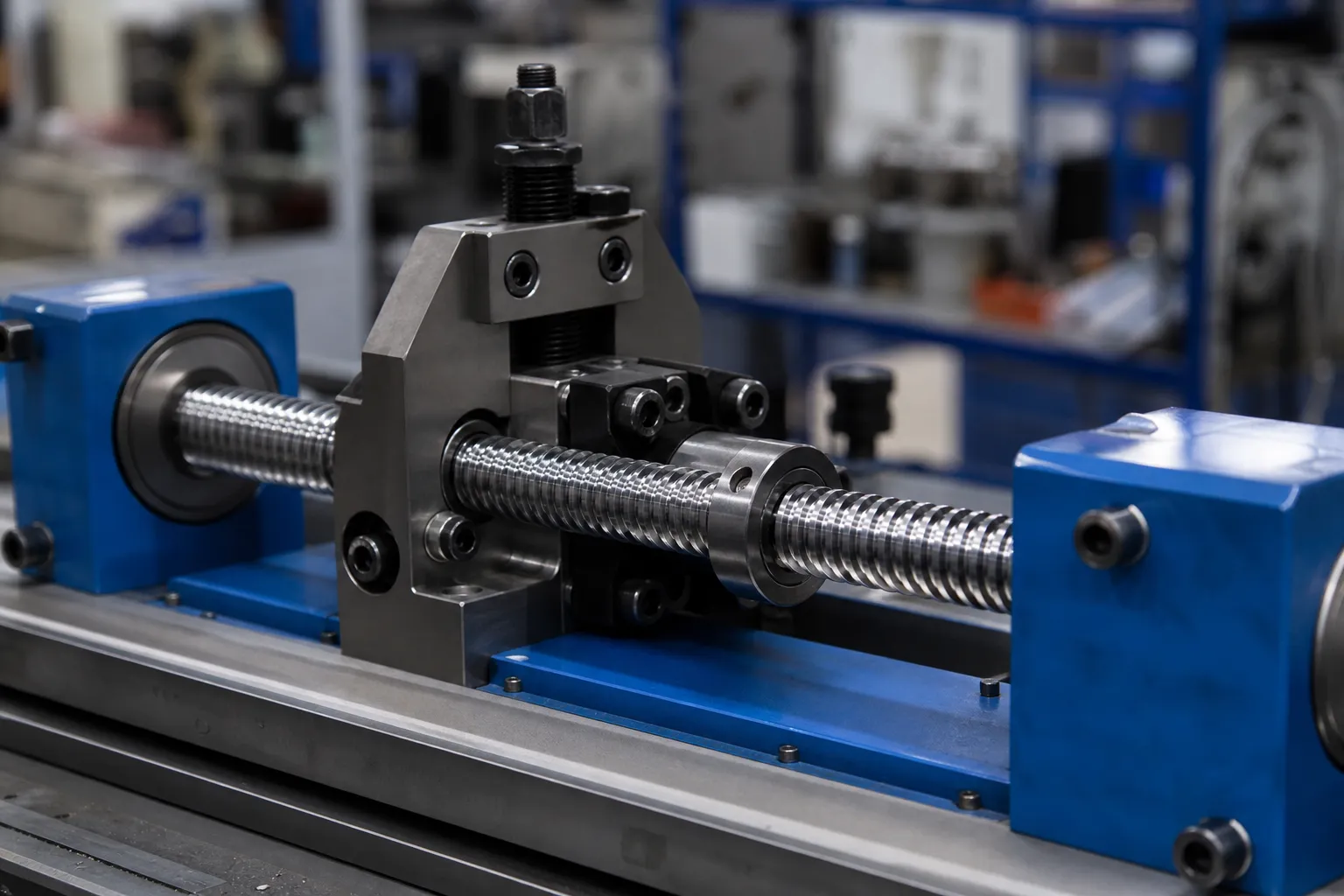
*Kaynak video çerçevesi.* Kompakt bir istasyondaki dişli vidayı gösterir ancak müşteri geometrisini de oluşturmaz, otomatik yükleme veya üretim kapasitesi.
Kurşun Vida Proje Gereksinimi
Müşteri, uygulamayı adım motoru kılavuz vidası olarak tanımlıyor ve motorun elektrik değerini şu şekilde bildiriyor: 2.33 VDC'de 1.5 A. Bu derecelendirme montajın tanımlanmasına yardımcı olabilir, ancak şaft sertliğini tanımlamaz, doğrultma kuvveti, ölçüm verisi veya kabul edilebilir salgı. Düzeltme önerisi vida çizimine dayanmalıdır, malzeme, ısıl işlem, iplik formu, süreç aşaması ve boyutsal tolerans.
“Dört parça” yazan satır, Ø3,5 × 508 mm”, müşteri aksini onaylayana kadar ikinci geometri için numune miktarı olarak değerlendirilir. Ø6.35 ile otomatik olarak birleştirilmemelidir. × 75 mm parça veya evrensel bir makine yelpazesi talep etmek için kullanılır.
| Proje Öğesi | Müşteri Girişi / Durum |
|---|---|
| İş parçası | Bir step motor uygulamasıyla ilişkili kurşun vida |
| Aday Aile A | Ø6,35mm × 75 mm; L/D ≈ 11.8 |
| Aday Aile B | Bildirilen dört örnek, Ø3,5 mm × 508 mm; L/D ≈ 145.1 |
| Motor Değeri | 2.33 VDC'de 1.5 A; yalnızca montaj tanımlaması, düzleştirme girişi değil |
| Güncel Ekipman | Müşteri, Galdabini ekipmanının önceki kullanımını bildiriyor |
| Malzeme / Sertlik | Onaylanacak |
| Konu Formu / Yol göstermek | Onaylanacak |
| Gelen Bükme | Temsili numuneler üzerinde ölçülecektir |
| Nihai Gereksinim | Doğruluk veya TIR, onaylanacak veri ve ölçüm konumları |
| Önerilen Yöntem | Kapalı döngü rotasyonel ölçüm ve korumalı nokta presleme düzleştirme |
İki Boyutlu Aileler Neden Ayrı Fizibilite Pencerelerine İhtiyaç Duyar?
Çapın bükülme sertliği üzerinde güçlü bir etkisi vardır, uzunluk hem destek davranışını hem de ölçüm hassasiyetini değiştirirken. The 75 mm vida, fikstür erişimini sağlayacak kadar kompakttır, Kısa destek aralıkları ve özellik konumu tasarıma hakim olabilir. The 508 mm vida çapına göre son derece incedir, böylece görünen okuması destek aralığına göre değişebilir, duruş, prob kuvveti ve kendi ağırlığı.
İki aile hâlâ tek bir modüler makine platformuna sığabilir, ancak bu sonuç örnek test gerektirir. Farklı desteklere ihtiyaç duyabilirler, prob aralıkları, basın kontak geometrisi, düzeltme artışları, yükleme yöntemleri ve hatta farklı ölçüm yönelimleri.
| Mühendislik Faktörü | Ø6.35 × 75 mm Aile | Ø3,5 × 508 mm Aile |
|---|---|---|
| Geometri | Kısa dişli mil | Ultra ince dişli şaft |
| Birincil Demirbaş Riski | Destekler için sınırlı alan, prob ve pres aracı | Kendinden sapma ve dengesiz uzun açıklıklı destek |
| Ölçüm Hassasiyeti | Özellik konumu ve ayna/destek hatası | Destek konumu, sonda kuvveti, duruş ve çevresel rahatsızlık |
| Düzeltme Stratejisi | Kısa açıklıklı, ince yer değiştirme noktası düzeltmesi | Çok konumlu destek ve fizibilite testinden sonra çok küçük aşamalı düzeltme |
| Taşıma | Manuel yuva veya kompakt otomatik besleme mümkün olabilir | Uzun parça kılavuzluğu ve dolaşmayı önleme işlemi muhtemelen gerekli |
| Paylaşılan Tarif Varsayımı | İzin verilmiyor | İzin verilmiyor |
Doğruluk, Salgı ve İşlevsel Veri
Doğruluk ve radyal salgı birbiriyle değiştirilemez. Doğruluk, bir elemanın ideal bir düz çizgiden sapmasını tanımlar. Radyal salgı veya toplam belirtilen salgı, parça tanımlanmış referanslar etrafında dönerken ölçülür ve bu nedenle seçilen veriye bağlıdır. Ayrımlar daha ayrıntılı olarak ele alınmıştır. şaft düzgünlüğü, kaçış ve TIR.
Hassas bir vida için, işlevsel referans genellikle rulman muylularıyla ilgilidir, destek biter, merkezler veya başka bir çizim verisi. THK, destek eksenine göre vida mili salgısının ölçülmesini açıklar, muylu kısımlarında destek ve şaft döndürülürken çeşitli eksenel konumlarda okumalar dahil. KURODA aynı şekilde bilyalı vida inceleme öğeleri arasında rulman montaj salgısını ve tüm vida mili merkezinin toplam salgısını veya eğriliğini listeler. Bu ilkeler, bir teklifin neden yalnızca dış çap ve uzunluğa dayandırılamayacağını göstermektedir.
| Kabul Öğesi | Garanti Öncesi Gerekli Tanım |
|---|---|
| Kontrollü Karakteristik | Şaft düzlüğü, radyal salgı, TIR veya montaj aşınması |
| Veri | Rulman muyluları, merkezler, destek uçları veya çizim tanımlı referans |
| Ölçüm Pozisyonları | Tam pürüzsüz çaplar, somun çevresi veya özel gösterge konumları |
| Ölçüm Duruşu | Yatay, dikey veya çizimle eşleşen destek koşulu |
| Prob Yöntemi | Temas kuvveti, uç geometrisi, dönüş hızı ve filtreleme |
| Nihai Sınır | Sayısal tolerans ve ölçü korelasyon yöntemi |
| Yüzey Kabulü | Günlüklerde izin verilen işaretler, iplik ve işlevsel olmayan alanlar |
Dişli Yüzey Neden Süreci Değiştirir?
Helisel bir iplik, pürüzsüz silindirik bir muylu ile aynı sinyali sunmaz. Doğrudan tepeye yerleştirilen bir prob diş geometrisini takip edebilir, Yalnızca şaft merkez çizgisi yerine yüzey değişimi veya eğime bağlı hareket. İşlevsel veriyi temsil ettiğinde düzgün bir yatak muylusu veya onaylı referans çapı üzerinde ölçüm yapılması tercih edilir.
Çizimde uygun düzgün bir ölçüm yüzeyi sağlanmıyorsa, çözüm özel bir ana somuna ihtiyaç duyabilir, somun çevresi ölçümü, optik bir yöntem veya başka bir doğrulanmış ölçüm kavramı. The method must be proven against the customer's final inspection; yalnızca bir video karesinden seçilmemelidir.
Düzeltme sırasında iplik koruması da aynı derecede önemlidir. Roton, kurşun vidalar için pres tipi düzleştirmeyi tavsiye ediyor ve düz çubuklara yönelik rulo doğrultma yöntemlerinin dişlere zarar verebileceği konusunda uyarıyor. Rehberliği, kontrollü tokmak hareketi ve koç ve destekler üzerinde yumuşak ayakkabılar gerektirir. Son temas malzemesi ve profilin yine de gerçek vida malzemesi için seçilmesi gerekir, sertlik, bitiş ve izin verilen temas bölgeleri.
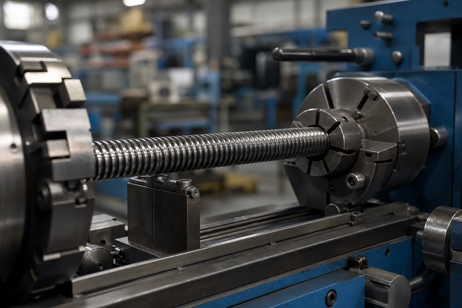
*Kaynak video karesi.* Veri seçimi, Temas yerleri ve ölçüm uygunluğu, onaylanmış çizimden doğrulanmalıdır..
Önerilen Doğrultma Yöntemi
Tercih edilen başlangıç konsepti, rotasyonel salgı ölçümü ile otomatik nokta presleme doğrultmasıdır.. Parça üzerinde anlaşmaya varılan bir veriye göre desteklenir, Bükülmenin büyüklüğünü ve açısal yönünü bulmak için döndürüldü, düzeltme açısına indekslenmiş, kontrollü bir artışla basıldı ve ardından tekrar ölçüldü.
Bu yaklaşım, takımın hassas diş tepelerinden kaçınmasına olanak tanır, omuzlar, alttan kesmeler ve bitmiş günlükler. Ayrıca kısa vida ve ultra ince vida için modele özel sınırları da destekler. Sürekli bir rulo düzleştirici, iplik oluşturulmadan önce bazı tek biçimli işlenmemiş parçalar için uygun olabilir, ancak bitmiş bir kurşun vida için uygun olduğu varsayılmamalıdır.. Daha geniş seçim kriterleri şu şekilde özetlenmiştir: Presle düzleştirmeye karşı silindirle düzleştirme.
MAE, uzun süreyi kamuya açık olarak tanımlar, Hassas düzleştirme uygulamaları olarak ince bilyalı vidalar, while Roton's application guidance favors press-type correction for threaded screws. Bu referanslar süreç ilkesini desteklemektedir, ancak rapor edilen müşteri büyüklüğünün zaten StraighteningTech örnek denemesini geçtiğini kanıtlamazlar.
Önerilen Kapalı Döngü Doğrultma İşlemi
İlgili 24 saniyelik video, kompakt bir döner mekanizmadaki dişli bir kurşun vidayı göstermektedir, Destek ve düzeltme istasyonu. Bitmiş bir ipliğin ve nokta düzeltme konseptinin varlığını doğrular. Bir step motor göstermiyor, bildirilen boyutlar, otomatik yükleme, tam bir üretim döngüsü, son tolerans veya dört uzun numune parçası.
| Adım | İşlem | Ana Kontrol |
|---|---|---|
| 1 | Parça ailesini tanımlayın ve tarifi yükleyin | önlemek 75 mm ve 508 mm ailelerinin doğrulanmamış ayarları paylaşması |
| 2 | Çıplak vidayı veya onaylı düzeneği yükleyin | Proses aşamasını onaylayın ve motor yataklarını veya kaplinlerini koruyun |
| 3 | İşlevsel veriyi oluşturun | Çizim onaylı günlükleri kullanın, merkezler veya özel destekler |
| 4 | Döndürün ve ölçün | Tanımlanan eksenel noktalarda bükülme büyüklüğünü ve açısal konumu kaydedin |
| 5 | Sinyali doğrula | İş parçacığına bağlı varyasyonu tespit et, dengesiz destek veya aşırı prob etkisi |
| 6 | Desteği seçin ve pozisyonlara basın | İplik hasarını önleyin, zayıf geçişler ve korunan yüzeyler |
| 7 | Kontrollü bir düzeltme uygulayın | Sınırlı yer değiştirme ve doğrulanmış bir kuvvet/darbe aralığı kullanın |
| 8 | Gerekli tüm noktaları yeniden ölçün | Yanıtı aynı veri ve destek koşulunda onaylayın |
| 9 | Sınırlar dahilinde tekrarlayın veya NOK'u sınıflandırın | Düzeltme sayımında dur, güç, vuruş veya tutarlılık sınırları |
| 10 | Sonucu kaydedin ve boşaltın | Gerektiğinde önceki/sonraki değerleri ve tarif verilerini saklayın |
Yükleme ve İşlem Aşaması
Tercih edilen üretim aşaması normalde motor monte edilmeden önce çıplak vidalı mildir, çünkü tamamlanmış bir düzeneğe basmak yükü motor yataklarına iletebilir, kaplin veya rotor. Müşterinin özellikle monte edilmiş motor vidası salgı düzeltmesine ihtiyacı varsa, fikstür ve kabul yöntemi montaj etrafında yeniden tasarlanmalı ve rulman yükü için doğrulanmalıdır.
Veri Desteği ve İlk Ölçüm
Mil, üzerinde anlaşmaya varılan referanslara göre desteklenir ve kontrollü bir döngü boyunca döndürülür. Ø3,5 için × 508 mm ailesi, destek konumları ve prob kuvveti ölçüm spesifikasyonunun bir parçası olmalıdır. Bir destek düzeniyle alınan bir okuma, korelasyon olmaksızın başka bir duruşta alınan bir okumayla doğrudan karşılaştırılamaz.
Sinyal Doğrulama
Kontrol, bir basma komutu vermeden önce tutarsız okumaları reddetmelidir. Olası nedenler arasında kirlenmiş destekler yer alır, gevşek bir ayna, uygun olmayan bir prob ucu, diş geometrisinin doğrudan takibi veya ultra ince şaftın kendi kendine sapması. Olasılık kontrolü ve tekrar ölçüm, her zirveyi bir bükülme olarak ele almaktan daha güvenlidir.
Güvenli Destek ve Düzeltme Pozisyonu
Onaylanan temas bölgeleri çizimden alınmalıdır. Bitmiş iplik armaları, keskin iplik salgıları, alttan kesmeler, omuzlar ve dayanma yüzeyleri korunabilir veya kısıtlanabilir. Yumuşak, konturlu ve değiştirilebilir destek/tokmak uçları markalamayı azaltabilir, ancak malzemeleri iş parçasıyla uyumlu olmalı ve aşınma açısından kontrol edilmelidir..
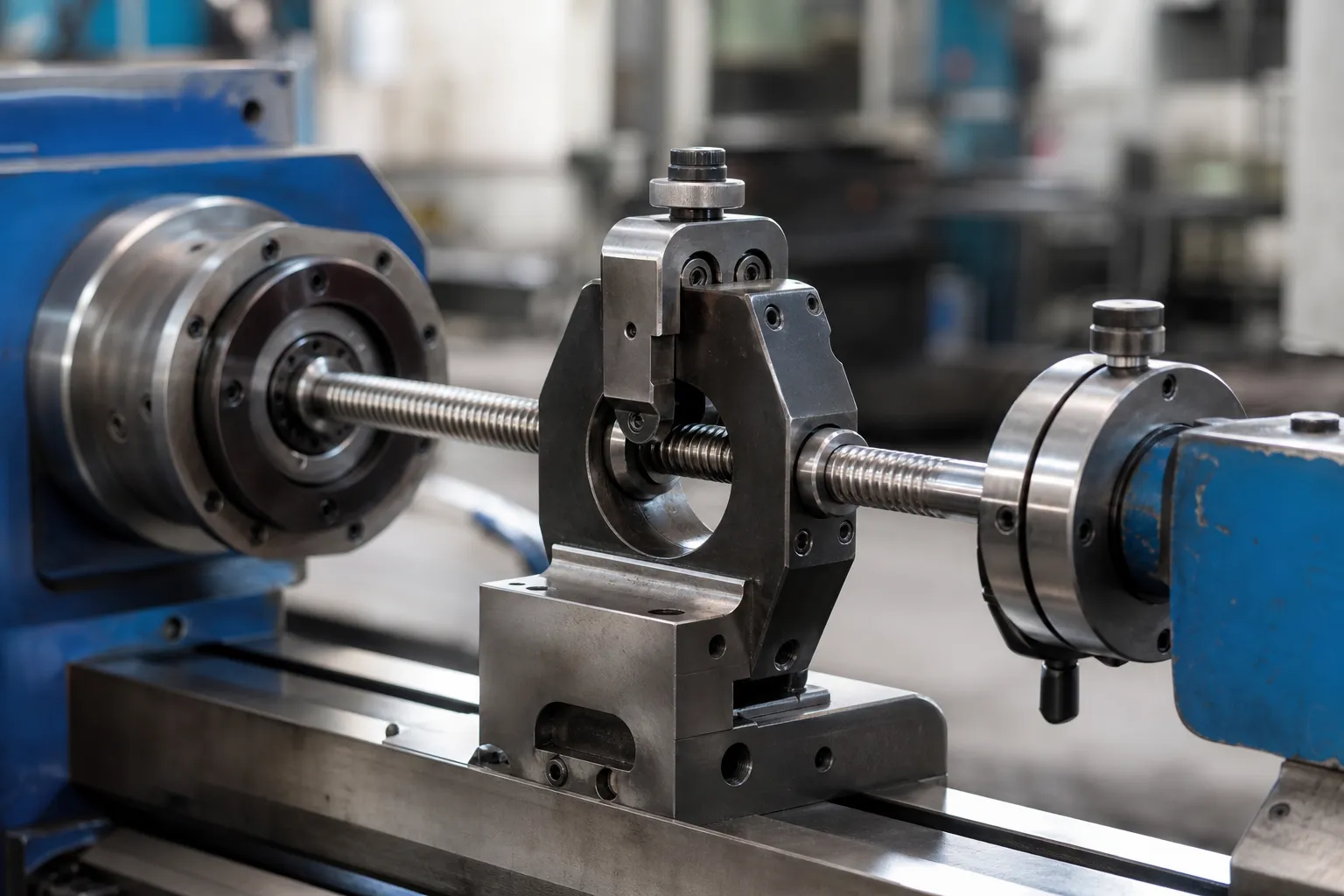
*Kaynak video karesi.* Yalnızca nokta düzeltme konseptini gösterir; oluk koruması ve kuvvet sınırları temsili numune doğrulaması gerektirir.
Kontrollü Düzeltme ve Geri Yaylanma
Düzleştirme, elastik geri yaylanmanın şaftı hedefe yaklaştırması için kontrollü aşırı bükülme gerektirir. Gerekli yer değiştirme evrensel bir yüzde değildir. Malzeme durumuna bağlıdır, çap, yerel iş parçacığı/kök geometrisi, destek açıklığı ve gelen viraj. Bu nedenle ilk düzeltme ihtiyatlı olmalı ve ölçülen numune yanıtından arındırılmalıdır..
Yeniden Ölçme ve Sıralama
Her düzeltmeden sonra, gerekli tüm noktalar aynı veri ve destek koşulu kullanılarak tekrar ölçülür. Bir parça yalnızca üzerinde anlaşmaya varılan karakteristik tolerans dahilinde olduğunda kabul edilir. Doğrulanmış kuvvete ulaşan bir parça, felç, döngü veya ölçüm tutarlılık sınırı tekrar tekrar basılmak yerine NOK veya mühendislik incelemesi olarak sınıflandırılır.
Ultra İnce Ø3,5 × 508 mm Mühendislik Kontrolleri
L/D oranı yaklaşık olarak 145.1 mevcut bilgi paketinde bu aileyi kontrol edici risk haline getiriyor. Makine, gerçek kalıcı bükülmeyi destek düzeninin neden olduğu sapmadan ayırt etmelidir, yer çekimi, temas kuvveti veya taşıma. Yükleme sırasında uzun parça kılavuzlarına ihtiyaç duyulabilir, ancak şaftın doğal durumunu maskelememeleri için ölçüm sırasında tekrar tekrar serbest bırakılmaları veya konumlanmaları gerekir..
| Risk | Olası Etki | Doğrulama Kontrolü |
|---|---|---|
| Destekler arasında kendi ağırlığı | Destek aralığı veya duruşla belirgin bükülme değişiklikleri | Destek konumlarını tanımlayın ve üretim göstergesini ilişkilendirin |
| Prob temas kuvveti | Sensör ölçtüğü konumu değiştiriyor | Düşük kuvvetli prob veya doğrulanmış temassız yöntem |
| Uzun desteksiz kuyruk | Titreşim ve kararsız açısal okuma | Ek kontrollü destekler veya alternatif bir yönlendirme |
| Küçük düzeltme penceresi | Tek vuruş virajı tersine çevirir veya lokalize eder | İnce yer değiştirme çözünürlüğü ve aşamalı düzeltmeler |
| Konu iletişim kişisi | Tepe hasarı veya eğimle ilgili ölçüm sinyali | Korumalı takımlama ve çizim onaylı ölçüm yöntemi |
| Taşıma | Karışıklık, ölçümden önce çizilme veya yeni bükülme | Kılavuzlu yükleme, kontrollü depolama ve parça ayırma |
Önerilen Makine ve Hücre Yapılandırması
| Modül | Önerilen Gereksinim | Proje Sınırı |
|---|---|---|
| Makine Konsepti | Hassas otomatik nokta düzeltme istasyonu | Her iki aile de test edildikten sonra seçilen son platform |
| Ölçüm | Düşük kuvvetli temaslı veya doğrulanmış temassız salgı sistemi | Üzerinde mutabakata varılan veri ve ölçüm yönteminin kopyalanması gerekir |
| Döndürme | Hassas ayna, merkezler veya dergi destekleri | Tek başına iş parçacığının veri olduğu varsayılmaz |
| Destekler | Ayarlanabilir, konturlu, değiştirilebilir kontaklar | Kısa ve ultra ince vidalar için ayrı düzenler |
| Basın Ünitesi | İnce deplasmanlı servo-elektrik veya hassas hidrolik düzeltme | Numunelerden belirlenen kuvvet ve strok aralığı |
| Takımlama | Uygun olduğunda yumuşak/korumalı şahmerdan ve destek parçaları | Malzeme ve temas işaretleri onay gerektirir |
| Kontroller | Modeli tarifleri, olasılık kontrolleri ve kapalı döngü düzeltmesi | Doğrulama olmadan paylaşılan tarif yok |
| Yükleniyor | Manuel, dergi veya otomatik taşıma | Parça stabilitesinden seçilmiş, hacim ve miktar |
| Veri | Gelen/son okumalar, düzeltme sayısı ve OK/NOK | Müşteri ihtiyacına göre tanımlanan izlenebilirlik seviyesi |
| Emniyet | Koruma, kilitler, aşırı yük ve anormal ölçüm alarmları | Üretim konfigürasyonu için gerekli |
Mevcut Ekipmanın Değiştirilmesiyle Karşılaştırma
Müşteri, Galdabini ekipmanını daha önce kullandığını bildiriyor ve alternatif bir kaynağı değerlendiriyor. Sorumlu bir karşılaştırma aynı temsili numune grubunu kullanmalıdır, aynı veri ve ölçü, aynı kabul toleransı ve aynı yüzey hasarı kriterleri. Ayrıca düzeltme oranını da karşılaştırmalı, döngü süresi, değişim, yanlış reddetmeler, bakım erişimi ve veri gereksinimleri.
Teklif, bir marka isminden "Galdabini'ye eşdeğer" iddiasında bulunmamalıdır, fotoğraf veya nominal çap aralığı. Eşdeğerlik yalnızca belgelenmiş bir kıyaslama veya üzerinde anlaşmaya varılan kısımlardaki FAT/SAT sonucuyla desteklenebilir.
| Karşılaştırma Öğesi | Gerekli Kanıtlar |
|---|---|
| Ölçüm korelasyonu | Aynı tarih, ölçüm noktaları ve kalibre edilmiş ölçüm cihazı karşılaştırması |
| Nihai kalite | Temsili normal ve en kötü durum kısımlarında öncesi/sonrası sonuçları |
| İplik koruması | Görsel, Düzleştirmeden sonra boyutsal ve işlevsel kabul |
| Süreç yeteneği | Düzeltme tarifi stabil hale geldikten sonra yeterli numune boyutu |
| Verim | Yükleme dahil zamanlanmış döngü, yinelemeler, boşaltma ve normal durmalar |
| Değişim | Her iki boyut ailesi için gösterilen aletler ve tarif geçişi |
| Güvenilirlik | Alarm, Deneme veya kabul sırasında bakım ve tekrarlanabilirlik incelemesi |
Nihai Teklif Öncesi Proje Doğrulaması
Temsili numuneler her iki geometriyi de kapsamalıdır, normal ve en kötü durumda gelen virajlar, her malzeme veya ısıl işlem koşulu ve ilgili tüm konu/günlük çeşitleri. Her deneme destek durumunu kaydetmelidir, ölçüm verileri, gelen dalga formu, düzeltme konumu, mevcut olduğunda kuvvet/darbe, nihai sonuç, düzeltme sayısı ve herhangi bir yüzey etkisi. Belgelenmiş numune testi kabul planının düzeltilmesi bu sonuçların nasıl bir onay kararına dönüşeceğini tanımlamalıdır.
Ø3.5 × 508 mm numune ailesi, düzeltme denemeleri başlamadan önce ölçümün tekrarlanabilirliği açısından ayrı ayrı değerlendirilmelidir. Gösterge parçanın bükülmesini destekten ayırt edemiyorsa- veya prob kaynaklı sapma, düzleştirme sonucu güvenilir bir şekilde garanti edilemez.
Kurşun Vida Doğrultma Teklifi İçin Gerekli Bilgiler
Lütfen vida çizimini sağlayın, iki boyutun ayrı model olup olmadığının doğrulanması, numune miktarı ve yıllık hacim, malzeme ve sertlik, iplik formu ve kurşun, ısıl işlem ve işleme aşaması, rulman yatağı ve merkez konumları, gelen salgı dağılımı, Nihai karakteristik ve veri, izin verilen destek/basın bölgeleri, korunan yüzeyler, motor montaj aşaması, hedefi geç, yükleme yönü ve temsili örnekler.
Bu girdiler çözüm ekibinin ölçüm yöntemini seçmesine olanak tanır, destek düzeni, basın çözünürlüğü, güvenli düzeltme penceresi, takımlama, Yalnızca motor değerinden veya videodan tahminde bulunmadan taşıma ve kabul planı.
Mühendislik Referans Temeli
- THK bilyalı vida doğruluğu ve montaj yüzeyi ölçümü destek eksenine göre salgıyı ve çeşitli eksenel konumlarda ölçümü açıklar.
- KURODA vidalı mil muayene kılavuzu çizim tabanlı inceleme öğeleri arasında rulman montaj salgısını ve toplam vida-şaft eğriliğini listeler.
- Roton kurşun vida düzeltme kılavuzu kontrollü pres tipi düzleştirme ve iplik koruyucu ayakkabılar önerir.
- MAE iş parçası uygulamaları uzun tanımlar, Hassas düzleştirme uygulamaları olarak ince bilyalı vidalar.
Bu kaynaklar yalnızca mühendislik ilkelerini destekler. They are not evidence of achieved results for the customer's reported parts.
SSS
Bir makine hem Ø6.35'i düzeltebilir mi? × 75 mm ve Ø3,5 × 508 mm kurşun vidalar?
muhtemelen, ölçüm aralığı ise, destekler, basın çözünürlüğü, işleme ve düzeltme penceresi her iki aileyi de kapsar. L/D farkı, bunun ayrı takımlarla ve numune denemeleriyle kanıtlanmasını gerektirecek kadar büyüktür, yalnızca çaptan varsayılmaz.
Şunu yapar mı? 2.33 VDC'de 1.5 Motor gücü düzeltme kuvvetini etkiler?
HAYIR. Step motor düzeneğinin tanımlanmasına yardımcı olur ancak vida malzemesini tanımlamaz, bükülme sertliği, iplik geometrisi, destek açıklığı veya düzeltme kuvveti.
Vida, motor montajından önce mi yoksa sonra mı düzeltilmeli??
Çıplak vidalı mil, düzeltme yükünün motor yataklarına veya kaplinlere iletilmesini önlediği için tercih edilen başlangıç aşamasıdır. Montaj düzeltmesi yalnızca özel bir fikstür ve onaylı bir yatak yükü ve salgı doğrulama planıyla mümkündür.
Makine doğrudan iplik üzerinde ölçüm yapabilir mi??
Yalnızca diş formu ve son muayene için doğrulanmış bir yöntemle. Pürüzsüz günlükler, yatak koltukları, merkezler, usta bir fındık, somun çevresi veya uygun bir optik yöntem daha güvenilir bir işlevsel referans sağlayabilir.
Presleme sırasında iplikler nasıl korunur??
Tarif, onaylı destek ve baskı bölgelerini tanımlar, konturlu değiştirilebilir kontaklar yükü dağıtırken. Yumuşak ayakkabı malzemeleri uygun olabilir, ancak nihai malzeme ve geometrinin gerçek vidalar üzerindeki yüzey ve işlevsel muayeneden geçmesi gerekir.
Proje videosu neyi kanıtlıyor??
Kompakt bir döndürme/destek/düzeltme istasyonundaki dişli bir kurşun vidayı göstermektedir. Bildirilen boyutları kanıtlamaz, motor montajı, otomatik besleme, döngü süresi, nihai tolerans veya uzun vida sonucu.
Alternatif makinenin mevcut Galdabini ekipmanına eşdeğer olduğu garanti edilebilir mi??
Yalnızca aynı veriyi kullanan aynı örnek kıyaslama sonrasında, ölçer, tolerans, yüzey kriterleri ve üretim koşulları. Bu kanıt olmadan markadan markaya eşdeğerlik sözü verilmemelidir.
Çözüm
Kılavuz vidanın doğrultulması işlevsel veriye bağlıdır, iplik koruması ve gerçek geometriyle eşleşen bir düzeltme penceresi. Bildirilen Ø6.35 × 75 mm ve Ø3,5 × 508 mm parçalar çok farklı ölçüm ve destek sorunlarını temsil eder, bu nedenle, bir modüler makine sonuçta her ikisini de kapsasa bile, bunlar iki onaylanmış tarif olarak ele alınmalıdır..
Çizimlerinizi gönderin, malzeme ve sertlik, Konu ayrıntıları, gelen ve hedef salgı tanımları, üretim aşaması, Fizibilite incelemesi için hacim ve temsili numuneler. StraighteningTech ölçümü geliştirecek, takımlama, Yalnızca motor gücüne veya nominal çapa göre ekipman önermek yerine, iş parçası kanıtları etrafında düzeltme ve kabul konsepti.