
Needle rollers are the slender cylindrical rolling elements of needle bearings — typically 1 do 5 mm in diameter with a length three to ten times the diameter, ground to micrometer tolerances and produced in volumes that reach millions of parts per lot. Inside the bearing, each roller is both a rolling body and a shaft: its own centerline straightness, roundness and surface finish directly set the bearing’s noise, friction and life. A roller that bows by a few micrometers cannot carry load evenly along its length, and the cage, the raceway, or the roller itself pays for it.
Needle roller straightening is therefore a high-volume micro-precision problem, and it is very different from the bearing ring problem on the same assembly line. The ring is a comparatively large, tog, low-part-count workpiece; the needle is a tiny, delicate, mass-produced one. A needle roller straightening solution has to answer five questions:
- What is the actual deviation population — how many rollers in a lot exceed straightness spec, and by how much?
- Which measurement system resolves micrometer straightness on a 2 mm del, repeatably, at production rate?
- Is correction even the right economic answer, or is sorting plus process correction upstream cheaper?
- Which correction route fits the roller’s geometry and hardness — through-feed rotary fine-straightening or selective point correction?
- How is the outgoing lot accepted — sampling plan, measurement capability, and surface-integrity evidence?
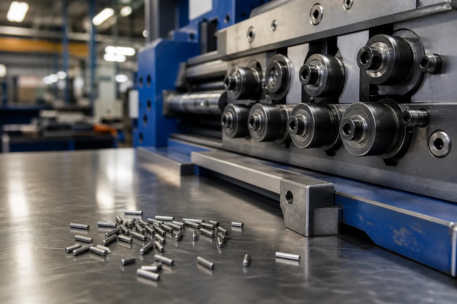
*Ilustracija inženirskega koncepta: needle rollers beside straightening equipment for a controlled correction study. To ni fotografija s strani stranke. Roller sizes, roll geometry and machine architecture require drawings and representative sample tests.*
What the Search Results Get Wrong
Search results for needle roller straightening mostly return wire and sheet straightening equipment — universal straightening machines for stock material — because “valjček” in that market means the machine’s own straightening rolls, not the workpiece. The actual workpiece-level problem appears in patents and bearing-industry practice: straightening thin parts in roller straightening machines is a documented industrial process, and needle producers publish process chains in which rollers are straightened after heat treatment and before or between grinding passes. If a supplier offer describes straightening “valji”, verify immediately whether they mean their tooling rolls or your rolling elements. This single vocabulary confusion wastes more enquiry time than any technical issue.
Where Needle Rollers Get Their Bend
Needle rollers are produced from wire or tube stock, rezati, headed or centerless-ground, toplotno obdelan, and finish-ground. Deviation enters at specific stages:
- Material inheritance. Rollers cut from drawn wire inherit the wire’s residual-stress asymmetry. If the incoming wire was straightened by others, its alternating-bend history — see roll versus rotary wire straightening — determines how stable the cut blanks stay.
- Toplotna obdelava. Hardening distorts thin sections asymmetrically; a crowned or relieved-end roller bows toward its weaker section. This is the main correctable deviation class, and the general post-heat-treatment rules in ravnanje po toplotni obdelavi apply.
- Grinding stress. One-sided or aggressive centerless grinding leaves residual stress that relaxes into a bow minutes or hours after the operation — which is why final straightness must be measured after a defined settling time, not at the grinder.
- Ravnanje. Tiny hardened parts in bulk flow are surprisingly damage-tolerant individually, but a pinch point in a chute can kink a whole stream. Kinked rollers are scrap.
Measurement at Needle Scale
Measuring straightness on a part a few millimeters long pushes conventional gauges to their limit:
Rotating Measurement with Micro-Probes
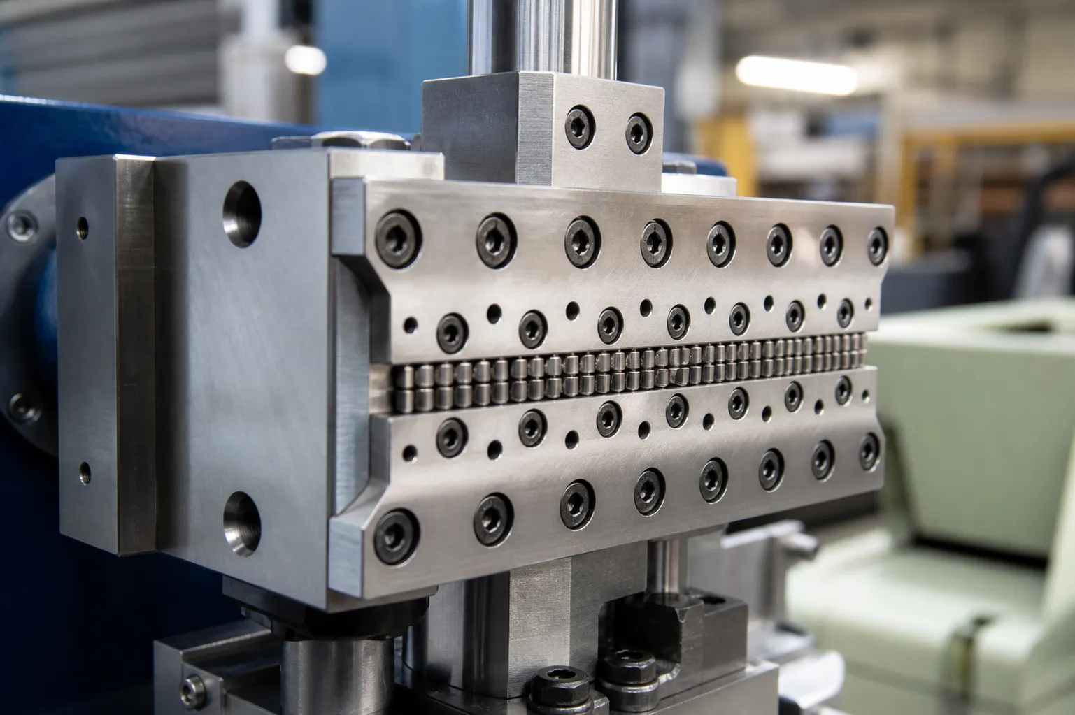
The roller is rotated on V- or prism supports while a high-resolution probe scans one or two planes. The measurement logic is the same multi-point runout mapping described for LVDT multi-point shaft measurement, miniaturized: at 1–2 μm tolerances, probe resolution must reach the sub-micrometer range, in roundness-versus-bend separation becomes decisive — a large share of apparent bend on small rollers is actually lobing from centerless grinding.
Optical and Pneumatic Methods
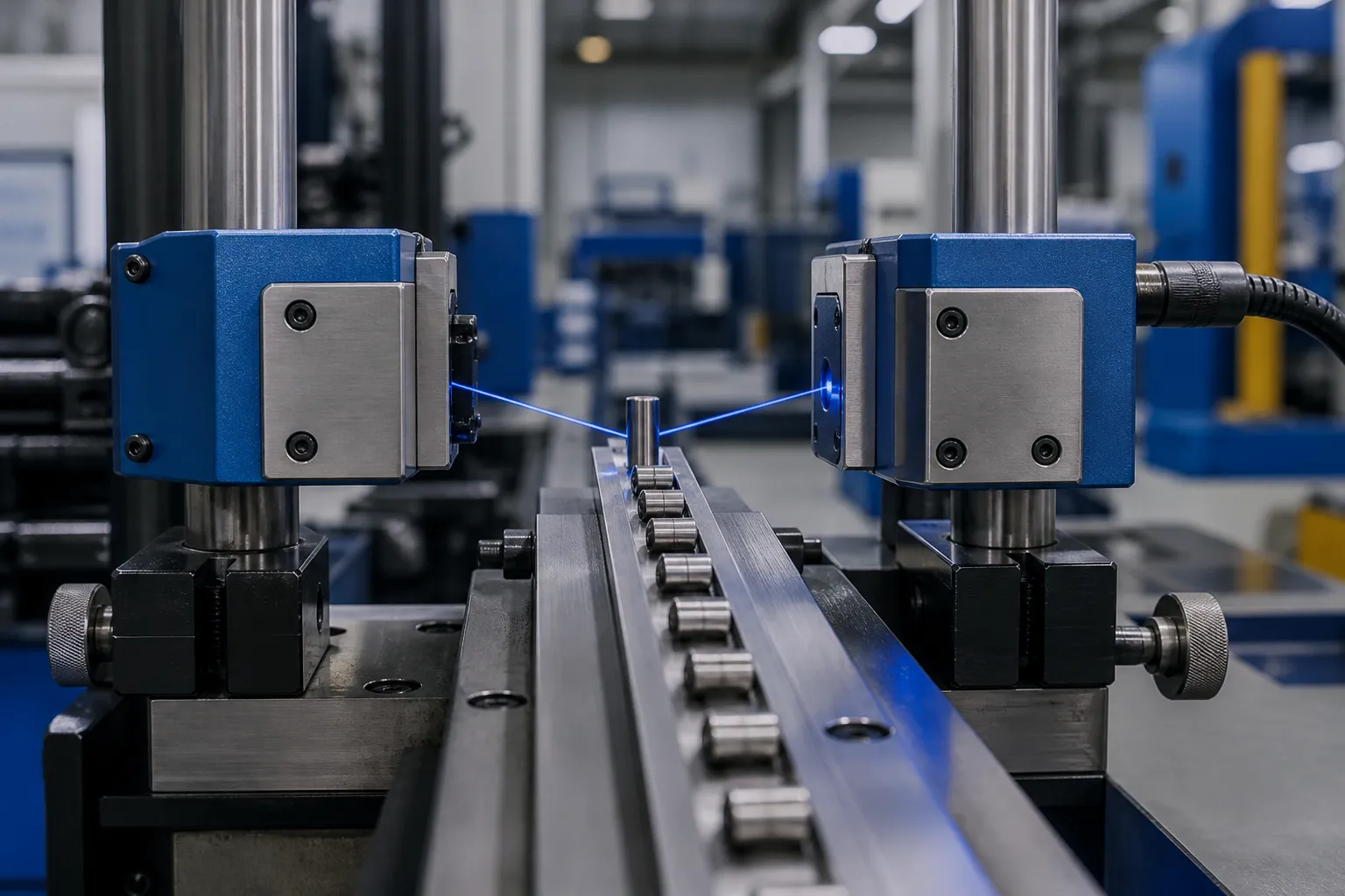
Laser micrometers and optical shadow-edge sensors measure diameter and, in multi-plane setups, axis deviation without contact — valuable both because contact on a ground roller surface is itself a damage risk and because throughput is high. Pneumatic gauges remain common for diameter sorting. Whatever the sensor, the gauge must survive a formal capability study; the discipline in merilnik R&R za ravnanje linij is non-negotiable when the tolerance and the gauge error are the same order of magnitude.
Correct or Sort? The Volume Decision
Before specifying any straightening machine, run the population statistics. If 2% of rollers in a lot exceed straightness spec, automated sorting with rework of the NOK fraction — the strategy analyzed in Omejitve razvrščanja in predelave NOK — is almost always cheaper than passing 100% of rollers through a correction process. If 60% are out, the problem is upstream (toplotna obdelava ali mletje), and straightening is a bandage that hides a process fault. Straightening earns its place in the middle band, and only for deviation classes that correction can actually fix.
Correction Routes for Rollers
Through-Feed Rotary Fine-Straightening
The industrial route for long-ish rollers with uniform cross-section is a pass through small-diameter, closely pitched straightening rolls that impose alternating bends of decreasing amplitude. This is the classic rotary straightening principle — the workpiece-side trade-offs against press straightening are compared in stiskalnica proti ravnanju z valji. For needles the rolls must be very small and very true, the guides must not mark the ground surface, and the process must be tuned so the outgoing residual-stress state stays stable — the Bauschinger effect is a live constraint when a roller has already seen alternating plastic strain in wire form.
Selective Micro-Pressing
For short rollers, crowned rollers, or small NOK fractions, selective correction on a precision micro-press with miniature supports is the alternative. The roller is mapped, pressed at the apex with a stroke measured in micrometers, and re-measured. Cycle counts per roller must be limited and logged. This route is slow but controllable, and it is the only realistic option when the roller has functional features that rule out roll contact.
Combined Sort-plus-Correct Lines
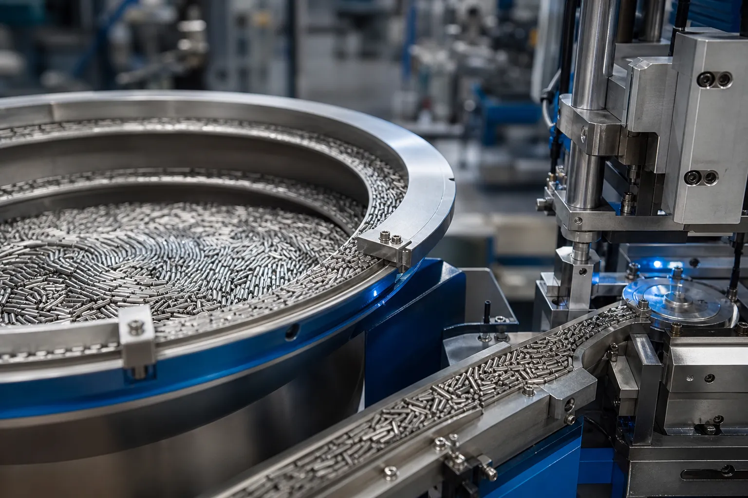
The production pattern that works at needle volumes is an integrated line: feed from a vibratory bowl, rotating measurement at one or two planes, sort gate into OK/NOK, and a correction station that receives only the NOK stream, re-measures after correction, and returns repeat-NOK parts to scrap. Whatever the layout, the acceptance question at lot level is statistical: sample plans must match the lot size and the straightness class, and rework history must be traceable.
From Lot Data to Line Layout
Once the deviation population is known, the line architecture follows from the numbers, not from preference:
| Konfiguracija | When It Wins | What It Costs |
|---|---|---|
| Sort only, no correction | NOK fraction low; scrap cheaper than handling NOK parts | Yield loss is permanent; upstream problem stays hidden unless data is analyzed |
| Sort plus offline correction cell | NOK fraction moderate; mixed roller types; frequent changeovers | Extra handling and logistics; batch traceability discipline |
| Inline correction in the grinding line | Stable single-roller production; deviation source understood and stable | Line coupling — a correction fault stops grinding; higher engineering effort |
| Correction before grinding | Bow large enough to affect grinding stock distribution | Requires re-validation: grinding after correction re-introduces stress |
Changeover and Traceability Discipline
Needle lines produce many roller variants in sequence — diameters, dolžine, crown profiles, straightness classes. Every changeover swaps supports, vodniki, measurement masters and correction recipes. Three disciplines keep a multi-variant line honest:
- Recipe binding. Each correction recipe is keyed to roller part number plus hardness lot. A recipe called up for the wrong diameter at best produces scrap, at worst produces rollers that pass the inline check and fail at the customer because the measurement span was wrong for the new length.
- Master-part verification. After every changeover, a certified master roller (or a zero-block) proves the measurement station before production resumes. On a line policing micrometer tolerances, skipping this step converts the next shift into scrap generation.
- Lot-level records. Straightness distribution, NOK fraction, correction cycle counts and scrap reasons recorded per lot turn the line into the upstream improvement signal — the data is what eventually retires the straightening step.
A final economic note: because rollers are cheap per piece and produced in enormous quantities, the straightening solution’s cost per corrected roller — including measurement, ravnanje, scrap and engineering attention — must be argued against the value of the recovered parts. It is entirely rational for the conclusion of a study to be “do not straighten, fix heat treatment”; a supplier who never presents that option is selling machinery, not a solution.
Merila sprejemljivosti
- Class straightness per the bearing drawing — commonly stated as a runout or bow limit in micrometers, measured at defined planes and support conditions.
- Form integrity: okroglost, diameter and crown profile re-verified after correction; the correction must not consume form tolerance.
- Celovitost površine: no guide or roll witness marks on the rolling surface. Any contact evidence on a finished roller surface is a bearing-life risk, not a cosmetic note.
- Measurement capability: gauge studies demonstrating that the straightness measurement itself is capable at the specified tolerance.
- Stabilnost: a defined settling or stress-relief policy so that rollers measured straight today do not drift out of tolerance before assembly.
Why Straightness Matters So Much in a Needle Bearing
It is worth being explicit about the failure physics, because it justifies the measurement spend. In a needle bearing the rollers carry line contact: load is distributed along the roller length only as long as the roller axis and profile conform to the raceway. A bowed roller concentrates the load at the high point of its bow, and contact stress there can multiply several-fold against the design value. The consequences arrive in sequence: localized surface fatigue initiates at the overload zone, the raceway picks up the damage signature, lubricant film breaks down at the contact, and the bearing announces the problem as noise, then heat, then seizure. None of these stages show anything wrong with a straightness gauge that was never capable of seeing the bow in the first place. Straightness class on the drawing is a life specification, and the correction process — or the decision not to correct — is only as good as the metrology behind it. That is the standard against which any needle roller straightening solution, and any supplier of one, should be evaluated.
Common Failure Modes in Needle Roller Projects
- Buying a stock-material machine by accident. The offer says “roller straightening machine” and straightens bar stock, not rolling elements.
- Correcting lobing as if it were bend. Centerless-grinding lobing masquerades as runout; pressing it wastes the part.
- Ignoring settling time. Straightness measured immediately after grinding drifts; the control plan must define when the measurement counts.
- Unbounded rework. Without a per-roller correction limit, the line burns capacity cycling a hopeless fraction of the lot.
- Gauge blindness. A measurement system with 1 μm repeatability cannot police a 2 μm tolerance; the line “passes” everything.
Sorodno branje: bearing ring straightening for the companion workpiece on the same bearing line, in medical mandrel straightening for another micro-precision slender-part reference. For a feasibility study, prepare the roller drawing with straightness class, deviation data from a representative lot, and the production volume per shift.