
O șină de cale ferată nu este o grindă în I generică, ghidaj liniar sau ax. Capul ei, țesătura și piciorul formează un profil funcțional asimetric, și cambra verticală, măturare laterală, twist, Geometria finală și controlul tensiunii reziduale pot necesita diferite căi de măsurare și corecție.
O soluție fiabilă de îndreptare a șinelor feroviare trebuie să răspundă la cinci întrebări înainte de alegerea mașinii:
- Care Vignoles, canelată, macara, limba, familia full-web sau special rail este în domeniu?
- Este sarcina de producție moara, fabricarea prezenței la vot, revendicarea atelierului, corectarea zonei de sudură sau întreținerea căii?
- Cum vor fi măsurate geometria verticală și laterală fără a confunda curbura intenționată, variație de profil, susține eroare sau răsucire?
- Care cap, panza sau terenurile de picior pot contacta suporturile si sculele, si care alergand, ecartament, sudură, gaura sau zonele prelucrate sunt protejate?
- Cum va fi remăsurată șina complet eliberată, inspectate și urmărite după corectare?

*Ilustrație de concept de inginerie a unei șine Vignoles într-o linie staționară de îndreptare și măsurare. Nu este o fotografie a site-ului clientului sau o afirmație de performanță. Forța reală a mașinii, intervale de sprijin, limitele de scule și de acceptare necesită specificația șinei controlate și teste reprezentative cu mostre.*
Definiți familia și traseul procesului
| Familie feroviară sau de proces | Diferența principală | Traseu pe această pagină |
|---|---|---|
| Sina Vignoles cu fund plat | Cap rotunjit, pânză îngustă și picior lat | Scop de îndreptare staționară primară |
| Sina canelata | Canelura și capul asimetric necesită date și scule dedicate | Familie separată și hartă de contact protejată |
| Limbă sau șină comutatoare | Geometrie funcțională prelucrată sau conică | Planul de măsurare și corecție specific funcției |
| Broasca sau componenta de trecere | Geometrie locală complexă și trasee de încărcare | Fixare personalizată și traseu de inspecție |
| Macara sau șină industrială | Profilul și sarcina diferă de șina de rulare feroviară | Intrări separate pentru rețetă și acceptare |
| Sina de moara noua | Controlul fluxului de producție și al stresului rezidual | Rolă sau linie de presă selectată din etapa de profil și proces |
| Sină recuperată | Purta, deteriora, istoric de sudare și service | Inspecție-primul traseu atelier |
| Corecție pe șină | Acces portabil, reținerea căii și siguranță operațională | În afara acestei pagini staționare de fabrică-celule |
| axă de cale ferată | Arbore forjat rotativ cu date de referință | Utilizați soluția de axă feroviară |
| fascicul I/H | Profil structural cu erori de fabricație flanșă/web | Utilizați soluția fasciculului, nu rețeta de șină |
Stierli-Bieger îl listează public pe Vignoles, canelată, limba, full-web și șine speciale, inclusiv îndreptarea și corectarea torsiunei. Geismar descrie o mașină de îndreptat șine orizontală continuă dedicată cu o rută opțională pentru celălalt avion. Aceste surse confirmă o piață de echipamente specializate; nu fac un set de scule valabil pentru fiecare profil de șină.
Înghețați etapa procesului
Producția Morii
Șina poate intra îndreptându-se după rulare, răcire sau tratament termic. Istoricul temperaturii, gradul materialului, profilul și tensiunile reziduale din amonte influențează retragerea și rezultatul eliberat. Propunerea trebuie să precizeze dacă aparatul de îndreptat este o mașină de producție în linie sau o stație de finisare separată.
Fabricație de prezență și trecere
Sine pentru limbă, broaștele și profilele speciale pot include prelucrarea, găuri, suduri sau curbură intenționată. Geometria aprobată nu poate fi dedusă numai dintr-o linie dreaptă de referință.
Recuperarea șinei
Sina folosită poate conține uzură pentru cap, ondulare, deformare locală, zone de sudare, coroziune, orificii pentru șuruburi sau deteriorare. Dispoziția de inspecție vine înainte de corectare. Geismar poziționează un dispozitiv de îndreptat șine dedicat pentru integrarea într-o linie de recuperare, susținerea unui traseu atelier distinct de producția de mori noi.
Corecția zonei de sudură
O eroare locală de geometrie a zonei de sudură necesită identitatea sudurii, revizuirea zonei afectate de căldură, măsurarea profilului și traseul de inspecție aplicabil. Îndreptarea nu poate înlocui inspecția sudurii sau repara o sudură inacceptabilă.
Definiți datele șinei înainte de măsurarea erorii
Șina ar trebui să fie referită din geometria funcțională definită de desen, nu oricare față este cel mai ușor de atins. Planul de măsurare ar trebui să definească:
- familia feroviară, sectiune si orientare;
- origine axială, starea finală și curbura dorită;
- număr de sprijin, spaţiere, înălțime și teren de contact;
- profil vertical de-a lungul direcției de rulare;
- măturare laterală raportată la capul necesar, caracteristică web sau picior;
- rotirea capului sau a secțiunii de-a lungul lungimii;
- şef local, verificări ale profilului web și piciorului acolo unde este necesar;
- dreptatea capătului și orice lungime exclusă a capătului;
- sudură, gaură, zone prelucrate și de tranziție;
- curatenie, scară, temperatura si starea de stabilizare;
- repetabilitate după eliberare, repoziţionarea şi schimbarea planului;
- correlation with the customer's rail gauge and final inspection system.
Citire dreptatea arborelui vs runout vs TIR pentru distincția generală între un profil de geometrie staționară și o indicație rotativă. O șină feroviară este în mod normal evaluată ca profil susținut; aplicarea terminologiei de curgere a arborelui la acesta creează un model de referință greșit.
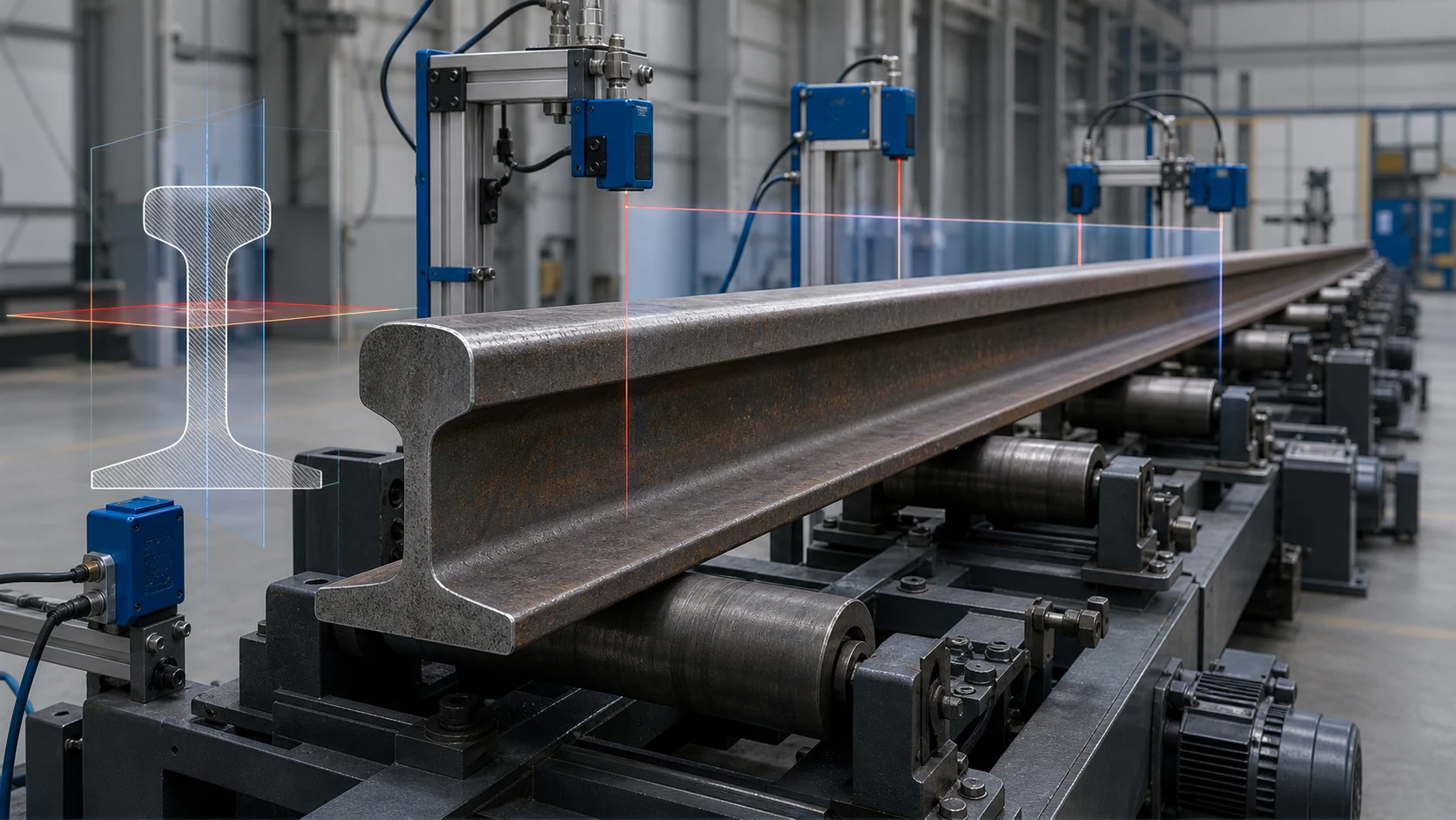
*Ilustrație de concept de inginerie a măsurătorilor verticale și laterale pe un profil de șină cap-web-picior. Nu este un ecartament prescris. Urmele reale ale senzorului, distanță între suport, curbura dorită și benzile de acceptare necesită desenul controlat al șinei și corelarea ecartamentului clientului.*
Moduri de eroare separate înainte de a aplica forța
| Semnal observat | Cauza posibila | Traseu obligatoriu |
|---|---|---|
| Curbură verticală lină repetată după resetarea suportului | Cameră verticală sau arc | Candidat pentru corecția în plan vertical validată |
| Abatere laterală lină repetată după repoziționare | Măturare laterală | Candidat pentru corecția cu acțiune secundară |
| Capul și piciorul se mișcă în direcții opuse pe lungime | Rotire sau răsucire a secțiunii | Măsurarea și sculele specifice torsiune |
| Schimbare locală bruscă de direcție | Kink, impact sau suprasarcină locală | Inspecție și revizuire tehnică înainte de corectare |
| Schimbări de semnal cu distanța dintre suport | Deformarea suportului, coborâre sau manevrare instabilă | Înghețați starea suportului și repetați măsurarea |
| Eroare mare numai lângă o sudură | Geometria zonei de sudură sau distorsiunea afectată de căldură | Calea de inspecție și corecție specifică sudurii |
| Suprafața de rulare este uzată în timp ce linia centrală este acceptabilă | Uzura capului sau pierderea profilului | Traseul de reprofilare sau respingere; îndreptarea nu reface materialul |
| Geometria se potrivește cu curba intenționată, dar nu reușește verificarea în linie dreaptă | Referință nominală greșită | Încărcați geometria de proiectare controlată înainte de clasificare |
| Corpul este acceptabil, dar zona finală este eliminată | Opriți răcirea, ferăstrăul, eroare de manipulare sau proces local | Corecție specifică sfârșitului sau revizuire a prelucrării |
Protejați Capul, Web și Picior
Zone protejate sau de revizuire implicite
- suprafețe de rulare finisate și măsurate fără o încercare de contact aprobată;
- margini web subțiri sau regiuni web neacceptate;
- marginile picioarelor unde încărcarea concentrată poate crea daune locale;
- zonele sudate și afectate de căldură până când inspecția permite corectarea;
- găuri pentru șuruburi, caracteristici ale comutatorului prelucrat și zone de atașare;
- mărci de identificare și trasabilitate;
- purtat, crăpat, sfărâmată, zone corodate sau deteriorate de impact;
- regiuni funcționale curbate sau conice intenționat.
Zone de contact potențial aprobate
- cap lat, terenuri de pânză sau picior selectate prin analize structurale și probe de probe;
- șei înlocuibile sau bare de pansament potrivite profilului șinei;
- contacte cu role controlate calificate pentru presiunea suprafeței și marcare;
- zone neterminate sau prelucrate ulterior, atunci când planul de proces permite în mod explicit contactul.
Fiecare forță de presare are nevoie de o cale completă de sprijin/reacție/încărcare. Un aranjament de scule care funcționează pentru un fascicul simetric poate supraîncărca un cap de șină, pânză sau picior deoarece secțiunea șinei este asimetrică.
Alegeți o arhitectură de corecție cu două planuri
Presă orizontală sau cu acțiune laterală
O presă hidraulică orizontală cu bonturi reglabile poate aborda măturarea laterală, îndoire orizontală locală și îndoire controlată a șinei. Stierli-Bieger descrie public bonturile mobile, control cu laser și capacitatea de a schimba direcția de îndoire fără a roti șina în unele configurații.
Propunerea ar trebui să definească:
- terenuri de reacție aprobate și punct de presă;
- distanțare și metoda de reglare a bontului;
- vigoare, limitele de deplasare și supraîndoire;
- logica de retur în funcție de familia și starea procesului;
- transportoare pentru produse lungi și acces cu macara;
- măsurare laterală eliberată după fiecare corecție mărginită.
Corecție verticală
Cambra verticală necesită o cale de încărcare verticală sau o stație validată de înclinare a șinei care transferă planul necesar în presă. Sistemul de manipulare nu trebuie să introducă o nouă îndoire în timp ce rotește sau repoziționează șina.
Linie de îndreptare cu role
Șina de freza de mare volum poate utiliza orizontală secvențială- și sisteme de rulare cu axă verticală. Fives descrie public dispozitivele de îndreptat șine folosind ambele orizontale- și mașini cu axă verticală, în timp ce un studiu de caz Iconsys descrie două mașini în serie cu poziție de rulare controlată, viteza si cuplul. Această arhitectură necesită o verificare a anvelopei familiei de producție și a tensiunii reziduale; nu este interschimbabil cu o presa de punct de atelier.
Îndreptarea prin torsiune
Răsucirea nu poate fi corectată în mod fiabil tratând șina ca un simplu arc vertical. Are nevoie de măsurare unghiulară de-a lungul secțiunii, scule de torsiune controlate, reținerea finală și remăsurarea eliberată.
Citire îndreptarea prin presa vs îndreptarea cu role înainte de a alege familia de corectare.
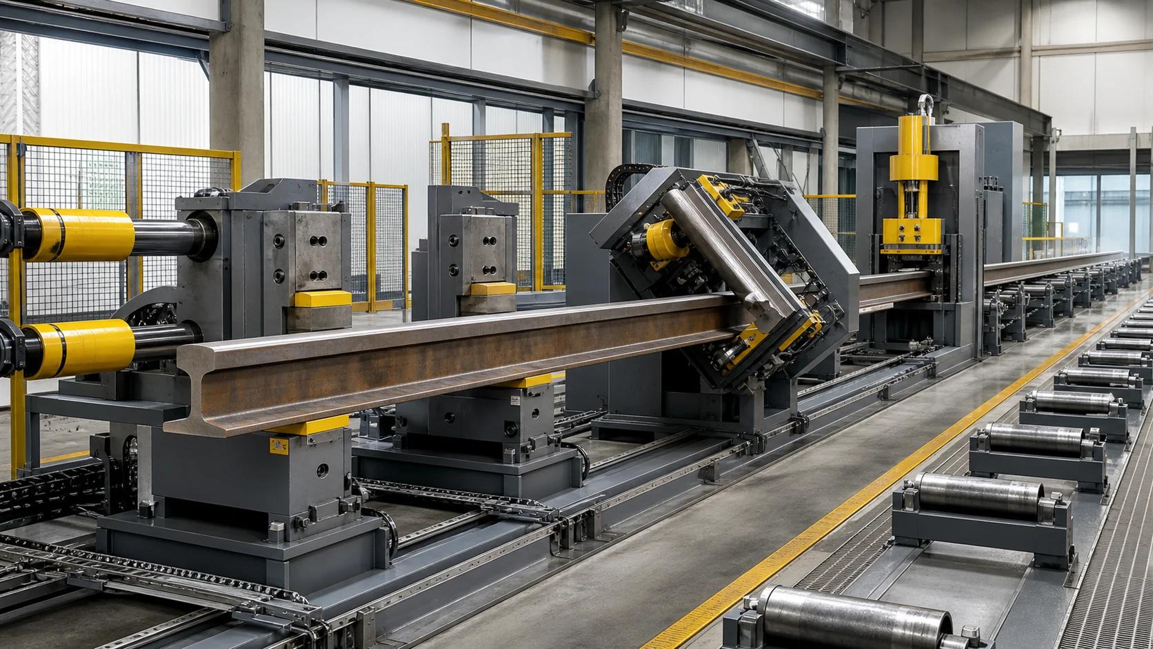
*Ilustrarea conceptului de inginerie a corecției cu acțiune secundară, schimbarea avionului și verificarea în aval. Nu este un aspect universal al mașinii. Manevrarea reală a șinelor, geometria reacției, vigoare, poziția de rostogolire și limitele tensiunii reziduale necesită inginerie de proiect și teste de probă.*
Introduceți manipularea grea în proces
Șinele lungi necesită o mișcare controlată prin măsurare și corecție. Conceptul de manipulare ar trebui să includă:
- transportoare cu role de intrare și ieșire motorizate;
- ghidaje de șină-familie care nu încurcă și nu deteriorează profilul;
- poziţionare axială pozitivă şi indexare controlată;
- macara sigură sau acces de transfer pentru configurare și recuperare;
- o metodă definită de schimbare a planului de corecție;
- gestionarea scării și a resturilor din jurul ghidurilor și senzorilor;
- paza, interblocări și zone de excludere sigure;
- logica de recuperare pentru pierderea energiei sau un ciclu de corecție întrerupt.
Sistemul de manipulare face parte din repetabilitatea măsurătorilor. O modificare a înălțimii transportorului sau a stării ruloului poate modifica profilul aparent și poate invalida o rețetă stocată.
Verificați șina eliberată, Nu forma încărcată
- Identificați familia feroviară, revizuirea desenului și etapa procesului.
- Confirmați starea inspecției și geometria dreaptă sau curbă dorită.
- Curățați zonele de măsurare și contact aprobate.
- Încărcați șina pe suportul înghețat și configurația de manipulare.
- Măsurați verticala, semnale laterale și de torsiune separat.
- Clasifica arcul, mătura, twist, îndoire, eroare în zona de sudare, eroare de uzură și instalare.
- Selectați apăsarea, rola, torsiune, cale de respingere sau inginerie-revizuire.
- Aplicați numai corecția delimitată alocată planului și zonei aprobate.
- Eliberați și stabilizați complet șina.
- Măsurați din nou în aceeași dată și condiție de suport.
- Repetați numai cu forță, deplasare, overbend, iterație și limite de suprafață.
- Completați profilul solicitat, suprafaţă, sudură, stres rezidual sau altă inspecție.
- Stocați profilul înainte/după, reţetă, dispunerea calitatii si evidenta trasabilitatii.
Configurați celula din jurul familiei șine
| Funcția celulară | Cerință feroviară-ferată |
|---|---|
| Identificare | Profil, nota, lungime, etapa procesului, curbura și trasabilitatea dorite |
| Manipulare | Transportoare lungi, poziționare axială, schimbare de avion și acces cu macara |
| Măsurare | Profil vertical, măturare laterală, rotația secțiunilor și verificările profilului local |
| Clasificare | Bomba, mătura, twist, îndoire, eroare în zona de sudare, eroare de uzură și instalare |
| Corecţie | Presă laterală, presa verticala, linie de rulare sau scule de torsiune în funcție de familie |
| Protecţie | Suprafețe de rulare/gabarit, web, marginile picioarelor, suduri, găuri și zone prelucrate |
| Verificare | Geometrie complet eliberată plus suprafața aplicabilă, verificări de sudură și tensiuni reziduale |
| Date | Profiluri înainte/după, înființat, forță/deplasare, inspecție și dispoziție finală |
Intrări pentru propuneri de care avem nevoie
Trimiteți următoarele înainte de selectarea echipamentului:
- desenele profilului șinei și lista de familie;
- gradul materialului, tratament termic și etapa de proces;
- intervalul de lungimi și mixul de produse anual sau de schimb;
- dreptatea intenționată sau curbura proiectată;
- vertical, lateral, twist și definiții de acceptare a zonei finale;
- sudură, gaură, prelucrate, hărți conice și cu suprafețe protejate;
- cap permis, pânză și terenuri de contact cu piciorul;
- distribuția erorilor de intrare și modurile de deteriorare cunoscute;
- suprafața necesară după procesare, sudură, verificări ale tensiunii reziduale sau NDT;
- bataie de linie, înălțimea transportorului și interfețele disponibile pentru macara/manipulare;
- bun reprezentativ, probe marginale și de respingere;
- gabarit client, formatul raportului și interfața de trasabilitate.
Acceptarea eșantion-test înainte de lansarea în producție
Eșantionul de încercare ar trebui să acopere plicul real al familiei de șine și ambele planuri de corecție. Ar trebui să verifice repetabilitatea suportului, corelarea senzorilor, marcarea contactului, clasificare vertical/lateral/torsiune, springback, manipularea schimbărilor de avion, geometria eliberată și inspecția necesară în aval.
Utilizați test de îndreptare a probei și ghid de acceptare pentru a îngheța matricea de testare și pachetul de dovezi.
Limită de inginerie
Îndreptarea poate corecta eroarea geometrică aprobată pe șina adecvată. Nu reface materialul uzat al capului, repara o fisura, califică o sudură inacceptabilă, replace reprofiling, sau să dovedească adecvarea căii fără autoritatea feroviară aplicabilă și procedura de inspecție.
Forța mașinii, aspectul rolei, anvergura bontului, distanță între suport, precizie, timpul ciclului, supraîncărcarea și numărul de iterații sunt rezultate ale propunerii. Trebuie să provină din familia feroviară controlată, stare materială, desen, eșantioane și indicator pentru clienți — nu dintr-un tabel cu specificații ale concurenței.
Solicitați o revizuire a îndreptării șinei feroviare
Every railway rail straightening project eventually hits the same two questions – cel straightener selection guide for shafts, tuburi si profile iar cel what a straightening machine costs answer them before your supplier meeting does.
Trimite masa familiei feroviare, desene, etapa procesului, hărți de eroare, traseul de inspecție și mostre reprezentative. Vom returna un model de referință și suport propus, hartă cu contact protejat, conceptul de corecție în două planuri, plan de manipulare, matricea eșantion-test și configurația echipamentului pentru revizuire.