
A straightening operation is a controlled plastic deformation event performed by pressing or rolling a hardened tool against the workpiece. Every such contact leaves evidence on the surface. Most of the time that evidence is invisible and harmless; occasionally it changes Ra by a full roughness grade or leaves a discrete indentation on a bearing journal. Whether your process survives its surface-finish requirement is decided by tool geometry, material hardness and contact stress — not by luck.
Managing surface roughness through a straightening cell means answering five questions up front:
- What does the drawing actually require — Ra, Rz or both, on which surfaces, measured in which direction?
- Which surfaces will the straightening tooling contact, and are those surfaces functional (ベアリング, 封印, fatigue-critical) or non-functional?
- Is the material soft enough that contact stress leaves a measurable mark — and how deep is acceptable?
- Will a downstream operation (研削, 研磨, コーティング) remove the affected layer, or does the straightened surface ship as-is?
- How will surface condition be verified at acceptance — by roughness parameters, indentation-depth limits, または両方?

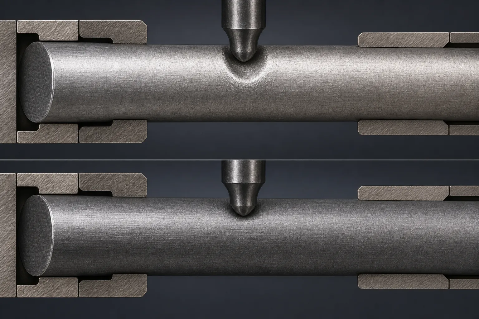
*エンジニアリングの概念図: tool-to-workpiece contact in a straightening operation. お客様現場の写真ではありません. Surface limits for a specific part depend on the drawing, the material and the tooling plan agreed during process design.*
What the Search Results Offer — and Where the Gap Is
DataForSEO の結果 surface roughness after straightening split into two groups: generic surface-finish references (metrology suppliers explaining Ra measurement, GD&T sites covering finish basics, marketplace pages listing achievable CNC roughness grades) and — a reminder that keywords need context — hair-care content that shares the word “矯正”. No result on the page addresses what a straightening machine’s roll or punch contact does to a machined metal surface. That is the gap this article fills.
This article is also deliberately scoped: our companion piece on 矯正時のツーリングマーク deals with visible marks as a defect class — identification, causes and prevention. Here the focus is the quantitative side: roughness parameters, how correction contact shifts them, and how to specify acceptance so finish and geometry are controlled together.
Roughness Parameters in One Minute
Ra is the arithmetic mean deviation of the profile from the centerline — the industry default, robust and well understood. Rz (in its common average-of-peaks form) responds more strongly to isolated deep features, which matters here: a single roll indentation barely moves Ra but can dominate Rz. When a straightening contact is suspected of damaging a surface, Rz and maximum-depth parameters are usually the more sensitive indicators. Typical achievable bands from machining references — grinding commonly delivering Ra 0.1–1.6 μm, finish turning 0.4–1.6 μm, rough turning well above — give the baseline against which any post-straightening change is judged.
| Process State (typical references) | Common Ra Range (μm) | Margin a Straightening Contact Consumes |
|---|---|---|
| Rough turned / as-rolled bar | 3.2 – 12.5 | Large — shallow tool marks vanish into the baseline texture |
| Finish turned | 0.4 – 1.6 | Moderate — visible roll marks can consume most of the budget |
| 地面 / precision finish | 0.1 – 0.8 | None — any mark is proportionally large; avoid contact or protect |
| Polished / functional (シール, ベアリング) | ≤ 0.4 | None — tool contact on these surfaces is a specification violation |
The table reads as a risk map: the finer the incoming finish, the less room any straightening contact has to hide. A roll track that is invisible on as-rolled bar stock is a rejectable defect on a ground shaft — same tool, same force, different consequence.

Three Contact Types, Three Signatures
Point-press contact (punch straightening). The correction punch concentrates the full pressing load on a small area, then the part springs back around it. The risk signature is a discrete local indentation whose depth tracks contact stress and material hardness. ソフト上, thin or finish-machined parts the visible dimple can exceed the roughness budget on its own; on parts with grinding stock remaining, the same dimple disappears in the next operation.
Roll contact (roller straightening). Rolls touch the workpiece along a moving line. The signature is a repeated helical or axial pattern of roll marks — usually shallow, but cumulative over multiple passes and worsening as roll surfaces age. Contact stress falls as roll diameter and profile radius increase, which is why roll groove selection is inseparable from finish protection; our guides on roll groove selection そして 表面保護工具 treat the geometry in detail.
Support and measurement contact. Vサポート, steady rests and probe tips leave their own evidence — chatter lines from rotating against a worn support, probe-tip witness marks on soft surfaces, center damage on parts rotated between centers. These are small individually, but a probe pushed onto a soft aluminum shaft with excess force can produce a permanent witness that no one planned for.
What Governs the Depth: 硬度, ジオメトリ, 力
Contact indentation depth follows from the same physics as hardness testing: a harder tool pressed into a softer body sinks until the contact area grows enough to carry the load. Three levers follow directly:
| Lever | Direction That Protects Finish | Trade-off |
|---|---|---|
| Workpiece hardness | Harder material marks less | Harder parts also tolerate less correction deflection — strategy changes, 見る 熱処理後の矯正 |
| Tool radius / roll diameter | Larger radius spreads load, shallower mark | Larger contact reduces localization of the correction force |
| Contact force per pass | より低い力, more passes | Cycle time increases |
| Tool surface condition | Polished, undamaged rolls | Worn rolls copy their damage onto every part — track with roller wear maintenance |
| Lubrication and cleanliness | Clean contact, no embedded debris | Debris at the interface acts as an abrasive and stamps itself into the surface |
Acceptable Change vs. Out-of-Spec Damage
Not every roughness change is a defect. A practical triage used in production cells:
- Non-functional surfaces with grinding or polishing downstream: modest Ra/Rz changes and shallow marks are absorbed by stock removal; verify remaining allowance covers mark depth with margin.
- Functional surfaces shipping as-machined (ベアリングシート, seal paths, fatigue-critical fillets): the straightening plan should avoid tool contact on these surfaces altogether — support and press elsewhere. Where contact is unavoidable, specify an indentation-depth limit in addition to Ra.
- Coated surfaces: deep marks telegraph through thin coatings; check that mark depth stays below a fraction of coating thickness or that a base-smoothing step exists.
- Soft non-ferrous parts (アルミニウム, 銅): mark depth risk rises sharply; dedicated protected tooling is the norm — the material side is covered in our aluminum vs steel straightening 比較.
Three Scenarios, Three Strategies
Scenario 1 — hardened shaft, grinding still to come. The part is straightened after heat treatment with 0.2–0.4 mm of grinding stock on journals. Tool contact marks within the stock layer are irrelevant to final finish; the specification should still cap indentation depth below the stock minimum so no mark survives grinding. The process question is geometric, not cosmetic — see 熱処理後の矯正.
Scenario 2 — soft aluminum component, 仕上げ面. Low hardness means every contact is a potential witness mark, and the same part may carry a tight cosmetic or sliding-surface requirement. The workable plan pushes all tool contact to non-functional zones, uses large-radius protected tooling, and audits contact tracks by sample. Material behavior — lower modulus, larger elastic recovery — compounds the marking risk as covered in our aluminum vs steel straightening 比較.
Scenario 3 — plated or coated part. Straightening precedes plating, and the coating is thin. Indentations that look harmless on bare metal telegraph through the coating as visible witness lines and can breach thickness minimums at edges. The specification needs an indentation-depth limit referenced to coating thickness, plus a finish audit immediately before the plating line.
Measuring Roughness After Straightening
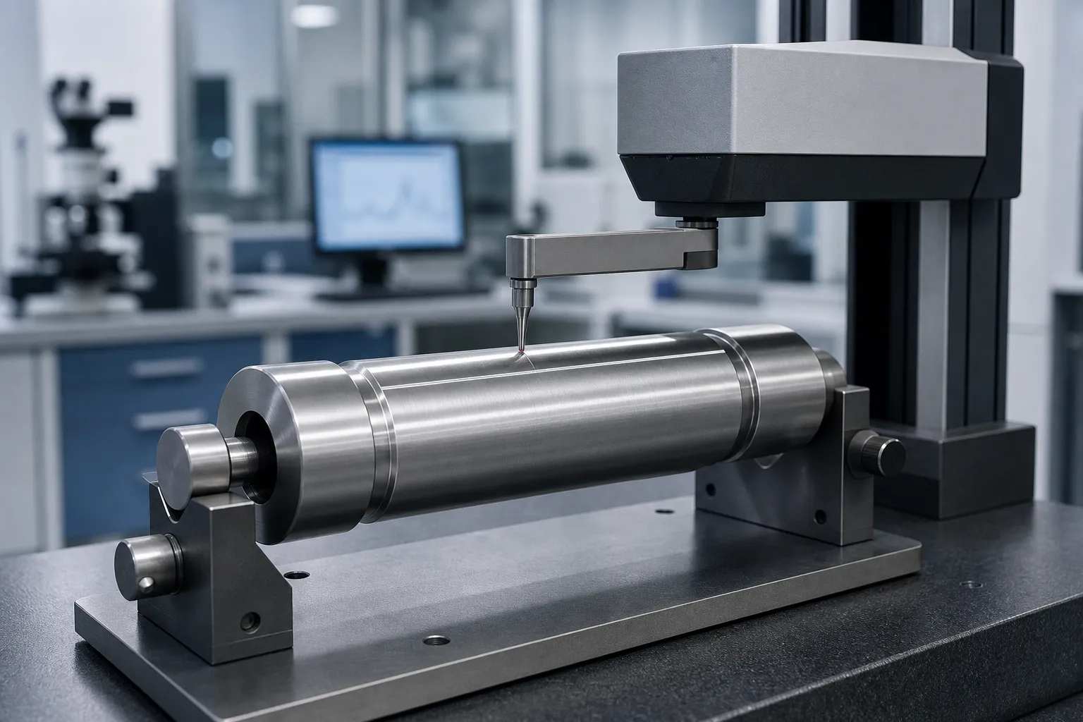
Where you measure determines what you find. A trace on a non-contacted surface documents the incoming machined finish; traces at the actual contact tracks document what the process added. On rotational parts, measure both axially (along the roll path) and circumferentially — roll marks are strongly directional, and a single-direction check can miss the worst orientation entirely. For indentation-type damage, a roughness parameter is the wrong instrument: profilometer traces across the dimple, or a depth-measurement method with sufficient lateral resolution, quantify what Ra averages away. When the straightening machine measures geometry inline, the finish check usually remains an offline audit — sample-based, at defined frequencies, on defined surfaces. The geometry measurement chain itself has its own validation path, で覆われている full-length profile straightness scanning.
Writing Finish Into the Straightening Specification
The cleanest practice is to make surface condition explicit in the process and acceptance documents: which surfaces are tool-contact zones and which are protected; an Ra (and where relevant Rz) limit post-straightening on defined surfaces; a separate indentation-depth allowance where contact on functional surfaces cannot be avoided; and the measurement method, direction and sample frequency. A straightening machine acceptance test built this way — our FATチェックリスト provides the framework — proves finish and geometry together, instead of discovering a finish conflict after installation.
Common Mistakes
- Specifying only Ra. Isolated indentations hide inside Ra; add Rz or an explicit dimple-depth limit on contact surfaces.
- Measuring one direction. Directional roll marks demand axial and circumferential traces.
- Judging marks on surfaces that will be ground anyway. Triage by downstream operations before rejecting parts.
- Ignoring roll condition. A damaged roll degrades every part identically — the defect looks “normal” until a fresh roll is mounted.
- Pressing on bearing journals by default. Where the bend map allows, move tool contact to non-functional zones.
よくある質問
Does straightening always worsen surface roughness?
いいえ. With generous roll radii, clean tooling and hard workpieces, measurable Ra change is often negligible — many shafts leave the cell indistinguishable from how they entered. The risk concentrates in soft materials, high contact forces, worn tooling and finish-machined functional surfaces. The purpose of a specification is to know which situation you are in before the first part runs.
Can roll marks be removed afterwards?
Shallow marks on surfaces with grinding or polishing stock are removed by those operations, provided remaining allowance exceeds mark depth. On finished surfaces there is usually no economical rework — re-polishing a bearing journal changes its geometry and diameter — so prevention through roll selection, protected tooling and contact placement is the practical route.
What Ra change should trigger concern?
The drawing sets the absolute line; the practical trigger is any systematic shift toward the limit or any step change after a tooling event. A cell that tracked Ra 0.4 μm after machining and reads 0.7 μm after straightening has consumed most of a typical finish budget and should investigate tool condition and contact stress before parts approach the limit.
Should roughness be measured before or after straightening?
Both, for different reasons. A baseline trace before correction on non-contact surfaces documents what machining delivered and separates inherited texture from process-added marks. Post-straightening traces at the actual contact tracks verify what the correction added. Cells that skip the baseline cannot prove whether a marginal surface came in that way — which matters when responsibility for rework is being assigned.
Plan the Surface Before You Press
Surface condition is a straightening deliverable, 思いつきではない. Pair this guide with 矯正時のツーリングマーク for defect diagnosis and 表面保護工具 for the hardware side. If your parts carry tight finish requirements and a bend problem — 弊社のエンジニアリングチームにお問い合わせください with the drawing and the finish specification, and we will map which surfaces can safely take correction contact.